Compression Fittings
Compression Fittings
Compression Fittings

Create successful ePaper yourself
Turn your PDF publications into a flip-book with our unique Google optimized e-Paper software.
<strong>Compression</strong> <strong>Fittings</strong><br />
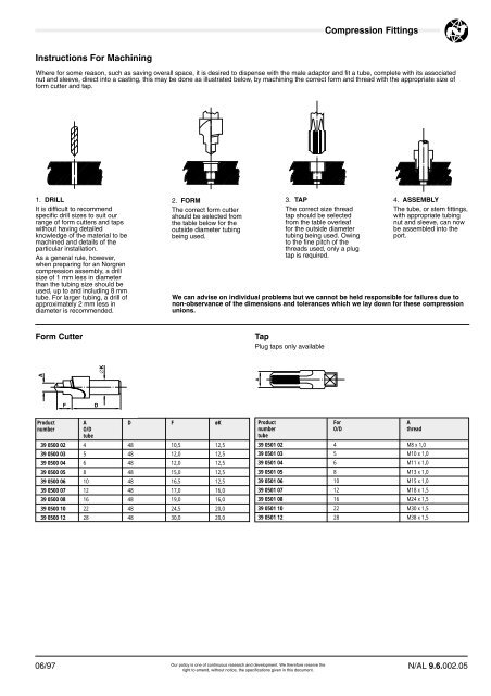
Instructions For Machining<br />
Where for some reason, such as saving overall space, it is desired to dispense with the male adaptor and fit a tube, complete with its associated<br />
nut and sleeve, direct into a casting, this may be done as illustrated below, by machining the correct form and thread with the appropriate size of<br />
form cutter and tap.<br />
1. DRILL<br />
It is difficult to recommend<br />
specific drill sizes to suit our<br />
range of form cutters and taps<br />
without having detailed<br />
knowledge of the material to be<br />
machined and details of the<br />
particular installation.<br />
As a general rule, however,<br />
when preparing for an Norgren<br />
compression assembly, a drill<br />
size of 1 mm less in diameter<br />
than the tubing size should be<br />
used, up to and including 8 mm<br />
tube. For larger tubing, a drill of<br />
approximately 2 mm less in<br />
diameter is recommended.<br />
2. FORM<br />
The correct form cutter<br />
should be selected from<br />
the table below for the<br />
outside diameter tubing<br />
being used.<br />
3. TAP<br />
The correct size thread<br />
tap should be selected<br />
from the table overleaf<br />
for the outside diameter<br />
tubing being used. Owing<br />
to the fine pitch of the<br />
threads used, only a plug<br />
tap is required.<br />
4. ASSEMBLY<br />
The tube, or stem fittings,<br />
with appropriate tubing<br />
nut and sleeve, can now<br />
be assembled into the<br />
port.<br />
We can advise on individual problems but we cannot be held responsible for failures due to<br />
non-observance of the dimensions and tolerances which we lay down for these compression<br />
unions.<br />
Form Cutter<br />
Tap<br />
Plug taps only available<br />
A<br />
A<br />
∅K<br />
F<br />
D<br />
Product A D F øK<br />
number<br />
O/D<br />
tube<br />
39 0500 02 4 48 10,5 12,5<br />
39 0500 03 5 48 12,0 12,5<br />
39 0500 04 6 48 12,0 12,5<br />
39 0500 05 8 48 15,0 12,5<br />
39 0500 06 10 48 16,5 12,5<br />
39 0500 07 12 48 17,0 16,0<br />
39 0500 08 16 48 19,0 16,0<br />
39 0500 10 22 48 24,5 20,0<br />
39 0500 12 28 48 30,0 20,0<br />
Product For A<br />
number O/D thread<br />
tube<br />
39 0501 02 4 M8 x 1,0<br />
39 0501 03 5 M10 x 1,0<br />
39 0501 04 6 M11 x 1,0<br />
39 0501 05 8 M13 x 1,0<br />
39 0501 06 10 M15 x 1,0<br />
39 0501 07 12 M18 x 1,5<br />
39 0501 08 16 M24 x 1,5<br />
39 0501 10 22 M30 x 1,5<br />
39 0501 12 28 M38 x 1,5<br />
Our policy is one of continuous research and development. We therefore reserve the<br />
06/97 N/AL 9.6.002.05<br />
right to amend, without notice, the specifications given in this document.