Download Eberspacher B1L-D1L Heater Technical Description ...
Download Eberspacher B1L-D1L Heater Technical Description ...
Download Eberspacher B1L-D1L Heater Technical Description ...

You also want an ePaper? Increase the reach of your titles
YUMPU automatically turns print PDFs into web optimized ePapers that Google loves.
Air heaters <strong>B1L</strong>/<strong>D1L</strong><br />
<strong>Technical</strong> <strong>Description</strong><br />
Installation instructions<br />
Operating Instructions<br />
J. <strong>Eberspacher</strong><br />
Eberspacharstr. 24<br />
D-7300 Essllngen<br />
Telefon (zentral)<br />
(0711) 31 09-0<br />
Telefax<br />
(0711) 3109-500<br />
<strong>B1L</strong><br />
Cat. no.<br />
Basic heater<br />
with standard equipment 12V 20 1590 05 00 00<br />
Universal installation kit 20 1575 80 00 00<br />
D 1 L<br />
Cat. no.<br />
Basic heater<br />
with standard equipment 12 V 25 1384 05 00 00 24V 25<br />
1385 05 00 00<br />
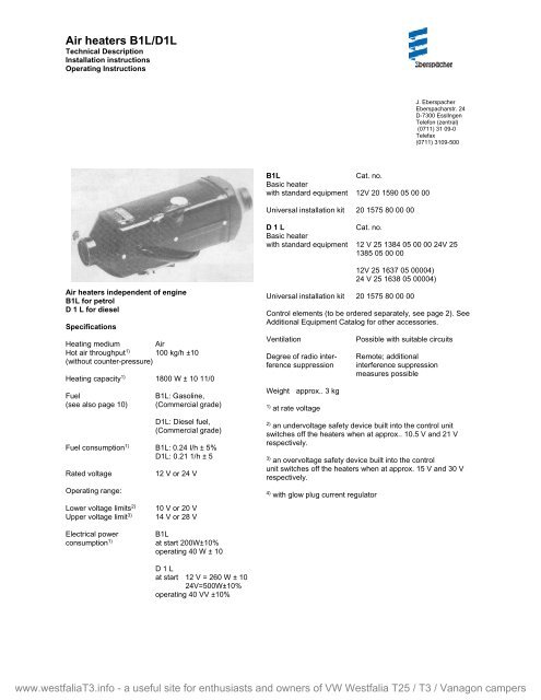
Air heaters independent of engine<br />
<strong>B1L</strong> for petrol<br />
D 1 L for diesel<br />
Specifications<br />
Heating medium Air<br />
Hot air throughput 1) 100 kg/h ±10<br />
(without counter-pressure)<br />
Heating capacity 1) 1800 W ± 10 11/0<br />
Fuel<br />
(see also page 10)<br />
<strong>B1L</strong>: Gasoline,<br />
(Commercial grade)<br />
<strong>D1L</strong>: Diesel fuel,<br />
(Commercial grade)<br />
Fuel consumption 1) <strong>B1L</strong>: 0.24 I/h ± 5%<br />
<strong>D1L</strong>: 0.21 1/h ± 5<br />
Rated voltage<br />
Operating range:<br />
12 V or 24 V<br />
12V 25 1637 05 00004)<br />
24 V 25 1638 05 00004)<br />
Universal installation kit 20 1575 80 00 00<br />
Control elements (to be ordered separately, see page 2). See<br />
Additional Equipment Catalog for other accessories.<br />
Ventilation<br />
Degree of radio interference<br />
suppression<br />
Weight approx.. 3 kg<br />
1)<br />
at rate voltage<br />
Possible with suitable circuits<br />
Remote; additional<br />
interference suppression<br />
measures possible<br />
2)<br />
an undervoltage safety device built into the control unit<br />
switches off the heaters when at approx.. 10.5 V and 21 V<br />
respectively.<br />
3)<br />
an overvoltage safety device built into the control<br />
unit switches off the heaters when at approx. 15 V and 30 V<br />
respectively.<br />
4)<br />
with glow plug current regulator<br />
Lower voltage limits 2)<br />
Upper voltage limit 3)<br />
Electrical power<br />
consumption 1)<br />
10 V or 20 V<br />
14 V or 28 V<br />
<strong>B1L</strong><br />
at start 200W±10%<br />
operating 40 W ± 10<br />
D 1 L<br />
at start 12 V = 260 W ± 10<br />
24V=500W±10%<br />
operating 40 VV ±10%<br />
www.westfaliaT3.info - a useful site for enthusiasts and owners of VW Westfalia T25 / T3 / Vanagon campers
Contents<br />
Page<br />
Scope of delivery/Cat. No 2,3<br />
Official regulations 4<br />
Installation instructions 4<br />
Typical installations/installation location 4, 5<br />
Installing the heater 5<br />
Principal dimensions 5<br />
Permissible installation positions/Fastening methods 6<br />
Running the heating air/determination of rating 7<br />
Running the combustion air 8<br />
Running the exhaust 8<br />
Fuel supply 9, 10<br />
Fuel at low temperatures 10<br />
Electrics/Wiring diagrams 11-16<br />
<strong>Description</strong> of operation 17, 18<br />
Malfunctions 18<br />
Scope of delivery:<br />
Item Qty. Design/Cat. No<br />
B 1 L<br />
Basic heater with standard equipment<br />
1 - 4 1 12 V 20 1590 05 00 00<br />
(Optional control elements)<br />
Standard equipment comprises:<br />
1 1 Basic heater 20 1593 01 (12 V)<br />
(not available alone)<br />
2 1 Control unit<br />
3 1 Fuel metering pump<br />
with built-in fuel filter<br />
4 3 T-piece6x6,8x6,12x6<br />
D 1 L<br />
1-4 1 Basic heater with standard equipment<br />
12 V 25 1384 05 00 00<br />
24 V 25 1385 05 00 00<br />
12 V 25 1637 05 00 00<br />
24 V 25 1638 05 00 00<br />
Standard equipment comprises:<br />
1 1 Basic heater<br />
25 1384 01 (12V), 25 1385 01 (24V)<br />
25 163701 (12V), 25 1638 01 (24V)<br />
(not available alone)<br />
2 1 Control unit<br />
3 1 Fuel metering pump<br />
with built-in fuel filter<br />
4 3 T-piece 6 x 6, 8 x 6, 1 2 x 6<br />
and additionally to be ordered for 1131 L and D 1 L<br />
Control elements, optional<br />
Timer<br />
Cat. No.<br />
12V 25 1482 89 25 00<br />
24V 251483891000<br />
Fasteners<br />
(only required for installation<br />
with screen)<br />
Cat. No.<br />
2514827001 00<br />
Timer with fasteners<br />
Cat. No.<br />
12V 25 1482 89 19 00<br />
24V 25 1483 89 02 00<br />
Universal switch<br />
Cat. No.<br />
25 1 380 89 04 00<br />
Bulb<br />
12V 207 00 005<br />
24V 207 00 006<br />
Room thermostat<br />
Cat. No.<br />
black 25 1 557 8001 00<br />
brown 25 1 557 8007 00<br />
5 1 Set of connectors 25 1 380 89 05 00<br />
- 1 Universal install kit 20 1 575 80 00 00<br />
www.westfaliaT3.info - a useful site for enthusiasts and owners of VW Westfalia T25 / T3 / Vanagon campers
www.westfaliaT3.info - a useful site for enthusiasts and owners of VW Westfalia T25 / T3 / Vanagon campers<br />
3
Approval, official regulations, general<br />
1. For vehicles registered in West Germany (subject to the road traffic<br />
regulations StVZO), the heaters are approved by the Federal Motor<br />
Vehicle Office and receive an official test symbol (131 L ~ S 133, D1<br />
L A V S 146) indicated on the name plate).<br />
The year of first operation is a requirement of German approval not<br />
representing a model number.<br />
2.If the heater is installed in special-purpose vehicles (e. g. vehicles<br />
transporting dangerous cargoes), the regulations applicable to such<br />
vehicles must be observed.<br />
3. The heater must not be operated in closed rooms, e.g. garages.<br />
The heater must always be switched off when the petrol tank is to<br />
be filled.<br />
4. The heaters must be installed by a workshop approved by the<br />
manufacturer and in compliance with the installation instructions.<br />
5. The heaters may only be used for the purpose specified by the<br />
manufacturer and in compliance with the operating instructions<br />
supplied with every heater.<br />
Operating the heater is not permitted where inflammable vapours or<br />
dust can build up (e.g. near fuel, coal or sawdust stores, grain silos<br />
etc.).<br />
Spray cans and gas cartridges in the vehicle must be kept out of the<br />
heating air current.<br />
6. The proposed installations in the installation instructions are only<br />
examples. Other installation locations are also permissible, provided<br />
they comply with the general installation requirements: the<br />
manufacturer should be consulted if necessary- In all other respects,<br />
differences from the installation instructions, particularly with regard<br />
to wiring (wiring diagrams), fuel supply, combustion air and exhaust<br />
ducts, and use of operating and control elements not supplied by the<br />
manufacturer, are only permissible with the written approval of the<br />
manufacturer. Failing that, the manufacturer's warranty is null and<br />
void for the entire heater system, as is the general operating permit.<br />
7. Every combustion process generates exhaust gas, which has toxic<br />
constituents. Because of this and the high temperatures generated,<br />
the exhaust duct must comply without fail with the installation<br />
instructions. Failure to comply with the instructions or operation of<br />
the heater in closed rooms (garages) harbours the risk of poisoning.<br />
8. When the heater or the heating system is damaged, an authorized<br />
workshop must be called in to repair the damage in an expert<br />
manner and using genuine spare parts.<br />
Makeshift repairs (on one's own initiative) or the use of non-genuine<br />
spare parts are dangerous, and therefore not permitted. When<br />
carried out in cars, they invalidate the general design approval of the<br />
heater and consequently the general permit of the vehicle.<br />
9. The warranty conditions are set forth in the heater booklet given to<br />
you by the after-sales service workshop when the heater is installed.<br />
Only our warranty conditions shall apply.<br />
Installation Instructions<br />
The suggestions put forward in these installation instructions are only examples. Possibilities other than those illustrated (e. g.<br />
with regard to the choice of installation location, means of running air) are also permissible, provided they meet the requirements<br />
of the West German road traffic regulations (StVZO), and if necessary after consultation with the manufacturer.<br />
Typical installations/installation location<br />
In excavator:<br />
D 1 L<br />
in the cab<br />
In truck:<br />
D 1 L<br />
1. on the rear wall of the cab<br />
2, under the seat of the driver<br />
4<br />
www.westfaliaT3.info - a useful site for enthusiasts and owners of VW Westfalia T25 / T3 / Vanagon campers
B 1 L/D 1 L<br />
in vehicle interior<br />
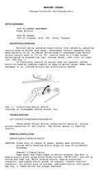
1.<strong>Heater</strong> under rear seat, inside or outside<br />
2. <strong>Heater</strong> in front of passenger seat.<br />
3. <strong>Heater</strong> on center console<br />
Installing the heater<br />
The B 3 L and D 3 L heaters are suitable and approved for<br />
installation in vehicle areas used by passengers.<br />
In the case of installation in passenger areas, the exhaust,<br />
combustion air and fuel lines in these areas must not have<br />
any detachable connections and must be splash-water-tight<br />
at the penetrations to the outside.<br />
For this reason, the heater must be mounted by its base on<br />
an outside panel of the vehicle or on its floor, using the seal<br />
seated on the base.<br />
The factory plate must be clearly visible even when<br />
installed.<br />
If necessary a second factory plate (duplicate) may be<br />
affixed, with the same information as the original, to a place<br />
on the heater clearly visible after installation, or to a cover<br />
placed in front of the heater. A second plate is not if the<br />
original is visible after removal of a cover without the<br />
necessary, aid of tools.<br />
5<br />
www.westfaliaT3.info - a useful site for enthusiasts and owners of VW Westfalia T25 / T3 / Vanagon campers
In general the heater should be installed in standard position,<br />
as shown.<br />
If this is not feasible, please consult the manufacturer.<br />
During starting an thermostatic operation a heater installed in<br />
the standard position may deviate, due to the inclination of the<br />
vehicle during motion, from this standard position up to ± 150 in<br />
both axes.<br />
Continuous heating operation after starting is even possible at a<br />
deviation from standard position of up to ± 300.<br />
With deviations exceeding ± 300 a reliable continuous heating<br />
operation is no longer possible. However, this does not lead to<br />
damage of the heater if the deviation occurs only for a short<br />
interval.<br />
Important: The plug connection piece must always face<br />
upwards.<br />
Fastening to the vehicle wall/floor<br />
Make penetrations in accordance with the template pattern.<br />
Templet pattern<br />
The holes for the 8 mm dia. vent lines and for the 10.5<br />
mm-dia. metering pump/control unit cable are not<br />
included in the template pattern, and must be drilled to<br />
suit the installation arrangement.<br />
The mating surface for the heater base must be smooth.<br />
To drill the penetrations and if necessary to smooth the<br />
mating surface, a special tool is available from the<br />
*This must be kept free. Check for free running of fan wheel<br />
If the mating surface sheet is too thin (criterion: less than 1.5<br />
mm), a reinforcing plate - Cat. No. 20 1577 89 00 03 - can be<br />
installed additionally on the outside.<br />
Special tool<br />
www.westfaliaT3.info - a useful site for enthusiasts and owners of VW Westfalia T25 / T3 / Vanagon campers<br />
6
Item Designation Component Cat. No rating<br />
1 Protective grid 0.4 20 1465 89 05 00<br />
2 Connection piece, 50 mm dia. 0.4 20 1575 80 08 01<br />
3 Hose clip, 50 - 70 mm dia - 2064 05 00 70<br />
4 Flex. pipe, 50 mm dia. lin. m. 1.0 per m 10 2114 29 00 00<br />
5 Protective grid, 50 mm dia. 0.1 20 1575 89 20 00<br />
6 Hood 0 20 1465 89 00 01<br />
7 Air outlet, rotatable, 50 mm dia. 1.25 20 1575 80 08 00<br />
- 90° bend of flex pipe, 50 mm dia. 0.4<br />
Do not connect too many components. The sum of the component ratings may not exceed the heater rating. See Additional<br />
Equipment Catalog for further parts.<br />
Item Designation Component Cat. No rating<br />
1 Protective grid 0.4 20 1465 89 05 00<br />
2 Connection piece, 50 mm dia. 0.4 20 1575 80 08 01<br />
3 0.3 flexible pipe, 50 mm dia. 0.3 20 2114 29 00 00<br />
4 1.0 m flexible pipe, 50 mm dia. 1.0 20 2114 29 00 00<br />
5 Reduction hood, 50 mm dia.straight 0.0 20 1465 89 00 01<br />
6 2 x 90° bends of flexible pipe 0.8<br />
(0.4 rating for each)<br />
7 Exhauster, rotatable 1.25 20 1575 80 08 00<br />
Sum of component ratings 4.15<br />
The sum of the component ratings does not exceed the heater<br />
rating of 10, installation is therefor permissible.<br />
When checking an installation, the average outlet temperature<br />
should not at the outlet point significantly exceed 110°C with<br />
an intake temperature of 20°C. This will ensure that the safety<br />
thermal cutout switch will not respond under normal<br />
operating conditions.<br />
Heating air intake openings shall be arranged in such a<br />
manner that exhaust from the vehicle's engine and from the<br />
heater cannot be expected to be sucked in under normal<br />
operating conditions, and the heating air cannot be<br />
contaminated.<br />
When operating as a recirculating heater, locate the inlet for<br />
the heating air in such a way that the outflowing hot air cannot<br />
be sucked directly in again.<br />
www.westfaliaT3.info - a useful site for enthusiasts and owners of VW Westfalia T25 / T3 / Vanagon campers<br />
7
Running the combustion air/Running the exhaust<br />
Permissible diameters, lengths, bends of combustion air and exhaust lines.<br />
Measurements in millimeters<br />
Permissible blend<br />
Exhaust lines<br />
Exhaust line: max. 180 0 B 1 L max. 500 mm long<br />
Combustion air line: max. 180 0 D 1 L max. 1000 mm long<br />
must not be exceeded.<br />
The scope of delivery includes an exhaust pipe, 270 mm long,<br />
with 900 bend, and a combustion air tube, 500 mm long, with<br />
90° bend.<br />
These can be shortened as required. Longer pipes are available<br />
as given in the Additional Equipment Catalog.<br />
Additional noise suppression is possible by installing an exhaust<br />
silencer (see chapter "Exhaust Parts" in the Additional<br />
Equipment Catalog). The permissible length of the exhaust line<br />
is reduced here by the length of the exhaust silencer.<br />
The combustion air must be sucked in from the outside, not<br />
from the passenger compartment or trunk.<br />
Do not install the intake opening facing the slipstream, but run<br />
it in such a manner that dirt and snow cannot enter and that<br />
any water which does enter can flow out.<br />
Exhaust lines must not project beyond the sides of the vehicle.<br />
They must be laid either with a slight slope or with 5 mm dia.<br />
holes at the lowest points for draining off condensate.<br />
Arrange the exhaust outlet and the combustion air opening<br />
such that the exhaust cannot be sucked back in directly.<br />
The exhaust outlet must be on the outside. Exhaust lines must<br />
be laid in such a way that neither the penetration of exhaust<br />
into the vehicle interior nor the intake of exhaust through the<br />
vehicle or heater blowers need be expected'), and that the<br />
operation of essential vehicle parts is not affected (ensure<br />
adequate clearance). Place the outlet opening of the exhaust<br />
line in such a way that it cannot be clogged by dirt and snow<br />
and that any water which does enter can run off. Do not install<br />
facing the slipstream.<br />
1) This requirement can be considered met if the outlet<br />
opening of the exhaust line is located at the usual places in<br />
motor vehicles, e.g. in engine compartment, in wheel case, on<br />
the vehicle underside, or on the rear of the cab.<br />
8<br />
www.westfaliaT3.info - a useful site for enthusiasts and owners of VW Westfalia T25 / T3 / Vanagon campers
Fuel supply<br />
The instructions given here should not be disregarded as deviations may cause malfunctions. 1. Fuel intake from fuel<br />
line to engine (usually in passenger cars):<br />
Precondition: the fuel line from the fuel tank to the engine must be tight, so that the flow of fuel is not interrupted when the engine<br />
is not running.<br />
Dimension a = max. 2000 mm for gasoline<br />
max. 5000 mm for diesel oil<br />
Dimension b =<br />
50 mm<br />
Dimension c = max. 300 mm<br />
Dimension d = max. 4 m for gasoline<br />
max. 6 m for diesel oil<br />
At all joints, fuel pipe (7) and connection pieces must touch.<br />
1 Tank<br />
2 Fuel branch<br />
3 Fuel tube, internal dia. 5 mm<br />
4 Fuel pre-filter (vertical, up to 30o downward if fuelline<br />
is tapped)<br />
Cat. No. 25 1226 89 00 37, only necessary if fuel is<br />
contaminated<br />
5 Fuel metering pump (150 to vertical, inclined upward)<br />
6 Fuel tube, internal dia. 3.5 mm<br />
7 Fuel pipe, plastic, internal dia. 1.5 mm<br />
8 Tank connection, internal dia. 2 mm<br />
9 Tube or plastic pipe (max. internal dia. 5 mm)<br />
10 Fuel pipe, plastic, internal dia. 2 mm<br />
2. Fuel intake separately from fuel tank or separate tank<br />
(usually in trucks, construction machinery, agricultural machinery)<br />
A = intake from above<br />
B = lateral intake at tank<br />
C = lateral intake or beneath it; metering pump below lowest fuel level<br />
Dimension a =<br />
max. 2000 mm with gasoline<br />
max.5000 mm with diesel oil<br />
With connection types A and B, the intake line - A<br />
includes tank connection (8) - including all connection<br />
points must have an internal dia. of 2 mm; for this<br />
reason, fuel pipe (10) and connections must touch<br />
each other at every joint.<br />
Dimension f =<br />
max. 500 mm with gasoline<br />
max. 1000 mm with diesel oil<br />
Dimension d = max. 4 m with gasoline<br />
max. 6 m with diesel oil<br />
www.westfaliaT3.info - a useful site for enthusiasts and owners of VW Westfalia T25 / T3 / Vanagon campers<br />
9
3. Permissible suction and pressure heads for installation per 1. and 2.;<br />
permissible positioning of metering pump<br />
Supply pressure from tank to metering pump:<br />
e = max. 3000 mm suction head: tank at zero pressure<br />
f =<br />
max. 500 mm with gasoline<br />
max. 1000 mm with diesel oil<br />
Check whether tank ventilation works properly<br />
intake from tank when underpressure occurs during operation<br />
(valve 0.03 bar in tank cap)<br />
f = max. 150 mm with gasoline<br />
max. 400 mm with diesel oil<br />
Pressure head metering pump to heater:<br />
g = max. 2000 mm<br />
Fuel line metering pump to heater should not have a slope if at all<br />
possible.<br />
4. Important<br />
Protect fuel lines, filter and metering pump from overheating; do<br />
not install near silencers and exhaust pipes. Temperatures above<br />
30° C lead to gas bubbles and problems with gasoline.<br />
Fuel pipes connected by means of a fuel tube.<br />
Fuel pipe sections must abut.<br />
When installing the fuel line, fuel filter and fuel metering pump<br />
near the rear axle, be sure to take the spring deflection of the<br />
rear axle into consideration.<br />
Cut fuel tubes and pipes to length only with a sharp knife. Cuts<br />
may not be indented and must be burr-free.<br />
For connection of the fuel branches, always use rubber tubing,<br />
never plastic pipe.<br />
Fuel grades/Fuel at low temperatures<br />
The heater can take without problem the same fuel you use in<br />
your tank- In the USA diesel fuel no. 1 and no.2. Admixture of<br />
used oil is not permitted<br />
The refineries automatically adapt their fuels to normal winter<br />
temperatures (Winter Diesel) Therefore difficulties can only<br />
arise at extremely low temperature (as in the engine - see the<br />
vehicle's instruction manual).<br />
If the heater is operated from a separate tank, the following<br />
rules must be observed: at temperatures above 0° C any type<br />
of diesel fuel can be used.<br />
If no special cold-weather diesel fuel is available at low<br />
temperatures, mix kerosine or gasoline according to the<br />
adjacent table.<br />
Temperature Winter Additive<br />
diesel oil<br />
From 0°C to -15°C** 100% -<br />
From -15°C to -25°C 50% 50 % kerosine<br />
or gasoline<br />
From -25°C to -40°C - 100% Kerosene*<br />
* or special winter diesel oils<br />
** or in accordance with fuel manufacturer's specifications<br />
The fuel line and the fuel pump must be filled with new fuel by<br />
operation for15 minutes.<br />
Fuel for special cases<br />
In special cases, the heaters can also be operated on extra<br />
light fuel oil (above 0°C) or kerosine If in doubt consult the<br />
manufacturer.<br />
www.westfaliaT3.info - a useful site for enthusiasts and owners of VW Westfalia T25 / T3 / Vanagon campers<br />
10
Electrics:<br />
Arrange electric cables, switches and control units in the vehicle<br />
in such a way that their correct functioning cannot be impaired<br />
under normal operating conditions.<br />
The following cable cross-sections must be observed between<br />
battery and heater, in order that the maximum permissible<br />
voltage losses in the cables (0.5 at 12 V rated voltage and 1 V<br />
at 24 V) are not exceeded.<br />
Fit the control unit so that it is protected from splash water<br />
(from both its own vehicle and preceding ones). Outside<br />
installation is thus not permissible. The unit is best arranged in<br />
the vehicle interior, with the plugs pointing downward.<br />
L+ + L- < 5 m - cross-section 4 mm2<br />
L+ + L- 5 to 8 m - cross-section 6 mm2<br />
If the positive cable is to be connected to the fuse box (e.g.<br />
terminal 30), the vehicle's cable too from the battery to the fuse<br />
box must be included in the calculation of the total line length,<br />
and if necessary redimensioned in accordance with the above.<br />
Smear plug and earth connections with contact protection<br />
grease outside the vehicle interior.<br />
The pilot light (built into the switch or timer) should be within<br />
the field of vision of the driver, or at least be visible to him<br />
without great effort.<br />
Install the room thermostat where it is sheltered from draughts<br />
and sunlight. Do not fit it to non-insulated outer walls.<br />
Parts list to wiring diagram B 1 L page 12<br />
and wiring diagrams D 1 L page 13-16.<br />
1.1. Blower motor<br />
1.2. Glow plug<br />
1.2.1. Glow plug drop resistor<br />
1.2.3. Temperature fuse<br />
1.4. Temperature switch<br />
1.5. Safety thermal cutout switch<br />
2.1. Control unit 2.1.1. Motor fuse<br />
2.2. Fuel metering pump 2.5.1. Relay for glow plug<br />
2.7. Main fuse 16 Amp.<br />
3.1.1. Universal switch<br />
3.2.1. Timer Optional addition parts<br />
3.3.1. Thermostat<br />
2.2.1. Circulation pump<br />
3.7. Glow plug current regulator<br />
5.1. Battery<br />
rt = red<br />
br = brown<br />
ws= white<br />
sw = black<br />
gn = green<br />
ge = yellow<br />
vi = violet<br />
www.westfaliaT3.info - a useful site for enthusiasts and owners of VW Westfalia T25 / T3 / Vanagon campers<br />
11
Wiring Diagram<br />
www.westfaliaT3.info - a useful site for enthusiasts and owners of VW Westfalia T25 / T3 / Vanagon campers<br />
12
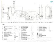
1 Hot-air blower 14 Combustion air tube F = cold air<br />
2 Electric motor 15 Exhaust pipe W = hot air<br />
3 Combustion air blower 16 Fuel metering pomp V = combustion air<br />
4 Glow plug 17 Fuel strainer A = exhaust<br />
5 Safety thermal cutout switch 19 Main fuse B = fuel<br />
6 Combustion chamber 20 Control unit<br />
7 Temperature switch 21 Motor current fuse<br />
8 Heat exchanger 22 Universal switch<br />
9 Casing 23 Timer<br />
10 Connection flange 24 Room thermostat<br />
11 Fuel connection 25 Timer 12 Screen for combustion air<br />
13 Plug area ventilation<br />
17<br />
www.westfaliaT3.info - a useful site for enthusiasts and owners of VW Westfalia T25 / T3 / Vanagon campers
<strong>Description</strong> of operation<br />
<strong>Heater</strong>s D 1 L and B 1 L are of identical design wherever practicable.<br />
The differing fuel types however make design differences unavoidable.<br />
Control elements<br />
A choice is possible between:<br />
1.Universal switch (22)<br />
Switch position: Heating or Ventilation<br />
If other switches generally used in motor vehicles are employed, they<br />
must be able to take at least 10 A.<br />
2. Timer (23125)<br />
Using the timer, the heater can be switched on at once or the switchon<br />
time can be preselected in advance.<br />
3. Room thermostat (24)<br />
A room thermostat can also be used in conjunction with the universal<br />
switch or timer. It should however be remembered that the load on the<br />
battery is greater and that wear on plugs will be heavier.<br />
Mode of operation<br />
The pilot lamp comes on when the heater is switched on. With a timelag<br />
of approx.. 5 sets., the hot-air blower starts to convey hot air, the<br />
combustion air blower combustion air and the fuel metering pump fuel,<br />
in exactly metered amounts, into the combustion chamber Fuel and<br />
combustion air here form an inflammable mixture which is ignited at<br />
the glow plug. The combustion gases now pass through the heat<br />
exchanger and activate the temperature switch, which switches off the<br />
glow plug. The hot air is heated at the heat exchanger and passes<br />
through the exhauster into the area to be heated. When the heater is<br />
switched off, the pilot lamp goes off, but the blower motor runs until the<br />
heater has cooled down. Then it is automatically switched off by the<br />
temperature switch.<br />
IMPORTANT! <strong>Heater</strong>s with undervoltage safety device may<br />
only be operated with the appropriate control units (with<br />
replaceable motor current fuse),<br />
You can remedy the following malfunctions yourself:<br />
1. The blower cannot be heard after the heater is switched on:<br />
a) Check the 16 A fuse in the cable harness of the heater.<br />
h) Check the motor current fuse in the control unit<br />
(heaters Nos. 25 1531 05 and 25 1532 05 only).<br />
Important! Only the following <strong>Eberspacher</strong> spare part fuse inserts<br />
(special monitored design) may be used:<br />
for 12 V fuse insert TT 4, blue marking, no 460 26 016 Cat. No., for<br />
two: 25 1531 05 02 00<br />
for 24 Vfuse insert TT 2, yellow marking, no 460 26 000 Cat. No., for<br />
two: 25 1532 05 02 00<br />
The use of other fuse inserts may lead to damage in the control unit in<br />
the event of a fault.<br />
c) Check the glow plug and replace it if necessary.<br />
2. After the heater is switched on, the blower only runs for about 3<br />
minutes, the heater does not ignite and automatically switches off.<br />
Briefly switch the heater off and back on again (not more than twice). If<br />
the heater still does not ignite, have the trouble seen to in a workshop.<br />
3. The heater goes off during operation:<br />
If the fault is due to overheating, switch the heater off, eliminate the<br />
cause of the overheating (e. g. blocked hot-air pipe), press the safety<br />
thermal cutout switch (1) and switch the heater back on.<br />
Controls and safety equipment<br />
The flame is monitored by the temperature switch- This switch acts on<br />
the safety switch in the control unit, which switches off the heater in the<br />
event of a malfunction.<br />
Sequence after switching on:<br />
a) The temperature switch switches off the glow plug when a stable<br />
flame has been obtained. In addition, after the heater has been<br />
switched off, it automatically stops the blower when the heater has<br />
cooled down.<br />
b) If the heater fails to ignite, it switches off automatically not more<br />
than 3 minutes after being switched on.<br />
If a defect in the blower motor has caused the heater to switch off, the<br />
motor current fuse installed in the control unit may have been tripped.<br />
Check it and replace if necessary. The heater can be switched back on<br />
by briefly switching it off and back again. If the motor current fuse<br />
blows repeatedly, have the blower fault remedied. Do not switch the<br />
heater back on more than twice. I f it still does not start, remedy the<br />
malfunction in accordance with the Troubleshooting and Repair<br />
Manual.<br />
c) Should the flame extinguish spontaneously during operation, the<br />
heater will automatically switch off after no more than 4 minutes. It can<br />
be switched back on in accordance with b).<br />
d) The safety thermal cutout switch stops the fuel metering pump if the<br />
maximum permissible temperature for the heating air is exceeded (e.<br />
g. in the event of the heating air ducts becoming blocked). The heater<br />
then switches off automatically. After removal of the cause of<br />
overheating and pressing of the knob on the safety thermal cutout<br />
switch, the heater can he put back into operation by switching it off and<br />
on again.<br />
e) If the glow plug is defective, the temperature fuse on the glow plug<br />
series resistor (D 1 L - 24 V only) has blown, or the electric line to the<br />
fuel metering pump is broken, the heater will not start.<br />
f) If the voltage drops below 10.5 V or 21 V, or rises above 15 V or 30<br />
V, as the case may be, the heater switches off automatically.<br />
Please remember that the heater does not start to work until about<br />
5 seconds after being switched on.<br />
The pilot lamp in the universal switch comes on immediately after the<br />
heater is switched on.<br />
The heater must never be switched on while the tank is being filled.<br />
The heater must not be operated in garages.<br />
When carrying out electric welding work on the vehicle, disconnect the<br />
positive pole from the battery and earth it, in order to protect the<br />
control unit.<br />
Only our warranty conditions are valid for warranty claims.<br />
18<br />
www.westfaliaT3.info - a useful site for enthusiasts and owners of VW Westfalia T25 / T3 / Vanagon campers