82078 64 pin chmos single-chip floppy disk controller - Intel
82078 64 pin chmos single-chip floppy disk controller - Intel
82078 64 pin chmos single-chip floppy disk controller - Intel

Create successful ePaper yourself
Turn your PDF publications into a flip-book with our unique Google optimized e-Paper software.
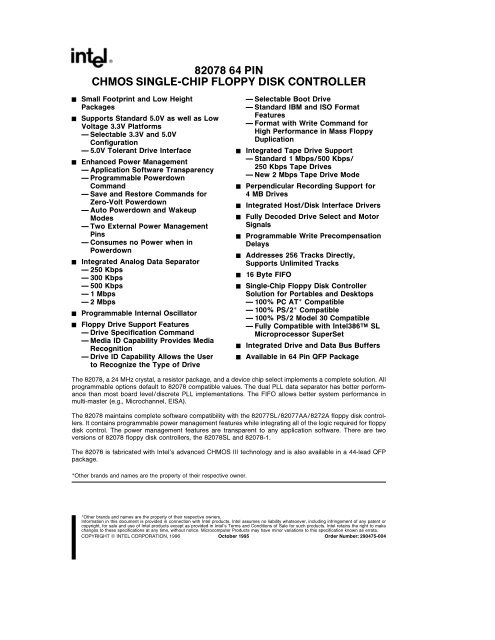
<strong>82078</strong> <strong>64</strong> PIN<br />
CHMOS SINGLE-CHIP FLOPPY DISK CONTROLLER<br />
Y<br />
Y<br />
Y<br />
Y<br />
Y<br />
Y<br />
Small Footprint and Low Height<br />
Packages<br />
Supports Standard 50V as well as Low<br />
Voltage 33V Platforms<br />
Selectable 33V and 50V<br />
Configuration<br />
50V Tolerant Drive Interface<br />
Enhanced Power Management<br />
Application Software Transparency<br />
Programmable Powerdown<br />
Command<br />
Save and Restore Commands for<br />
Zero-Volt Powerdown<br />
Auto Powerdown and Wakeup<br />
Modes<br />
Two External Power Management<br />
Pins<br />
Consumes no Power when in<br />
Powerdown<br />
Integrated Analog Data Separator<br />
250 Kbps<br />
300 Kbps<br />
500 Kbps<br />
1 Mbps<br />
2 Mbps<br />
Programmable Internal Oscillator<br />
Floppy Drive Support Features<br />
Drive Specification Command<br />
Media ID Capability Provides Media<br />
Recognition<br />
Drive ID Capability Allows the User<br />
to Recognize the Type of Drive<br />
Y<br />
Y<br />
Y<br />
Y<br />
Y<br />
Y<br />
Y<br />
Y<br />
Y<br />
Y<br />
Selectable Boot Drive<br />
Standard IBM and ISO Format<br />
Features<br />
Format with Write Command for<br />
High Performance in Mass Floppy<br />
Duplication<br />
Integrated Tape Drive Support<br />
Standard 1 Mbps500 Kbps<br />
250 Kbps Tape Drives<br />
New 2 Mbps Tape Drive Mode<br />
Perpendicular Recording Support for<br />
4 MB Drives<br />
Integrated HostDisk Interface Drivers<br />
Fully Decoded Drive Select and Motor<br />
Signals<br />
Programmable Write Precompensation<br />
Delays<br />
Addresses 256 Tracks Directly<br />
Supports Unlimited Tracks<br />
16 Byte FIFO<br />
Single-Chip Floppy Disk Controller<br />
Solution for Portables and Desktops<br />
100% PC AT Compatible<br />
100% PS2 Compatible<br />
100% PS2 Model 30 Compatible<br />
Fully Compatible with <strong>Intel</strong>386TM SL<br />
Microprocessor SuperSet<br />
Integrated Drive and Data Bus Buffers<br />
Available in <strong>64</strong> Pin QFP Package<br />
The <strong>82078</strong> a 24 MHz crystal a resistor package and a device <strong>chip</strong> select implements a complete solution All<br />
programmable options default to <strong>82078</strong> compatible values The dual PLL data separator has better performance<br />
than most board leveldiscrete PLL implementations The FIFO allows better system performance in<br />
multi-master (eg Microchannel EISA)<br />
The <strong>82078</strong> maintains complete software compatibility with the 82077SL82077AA8272A <strong>floppy</strong> <strong>disk</strong> <strong>controller</strong>s<br />
It contains programmable power management features while integrating all of the logic required for <strong>floppy</strong><br />
<strong>disk</strong> control The power management features are transparent to any application software There are two<br />
versions of <strong>82078</strong> <strong>floppy</strong> <strong>disk</strong> <strong>controller</strong>s the <strong>82078</strong>SL and <strong>82078</strong>-1<br />
The <strong>82078</strong> is fabricated with <strong>Intel</strong>’s advanced CHMOS III technology and is also available in a 44-lead QFP<br />
package<br />
Other brands and names are the property of their respective owner<br />
Other brands and names are the property of their respective owners<br />
Information in this document is provided in connection with <strong>Intel</strong> products <strong>Intel</strong> assumes no liability whatsoever including infringement of any patent or<br />
copyright for sale and use of <strong>Intel</strong> products except as provided in <strong>Intel</strong>’s Terms and Conditions of Sale for such products <strong>Intel</strong> retains the right to make<br />
changes to these specifications at any time without notice Microcomputer Products may have minor variations to this specification known as errata<br />
COPYRIGHT INTEL CORPORATION 1996 October 1995<br />
Order Number 290475-004
<strong>82078</strong> <strong>64</strong> Pin CHMOS Single-Chip Floppy Disk Controller<br />
CONTENTS<br />
PAGE<br />
CONTENTS<br />
PAGE<br />
10 INTRODUCTION 8<br />
20 MICROPROCESSOR INTERFACE 9<br />
21 Status Data and Control<br />
Registers 9<br />
211 Status Register A (SRA PS2<br />
Mode) 9<br />
212 Status Register A (SRA<br />
Model 30 Mode) 10<br />
213 Status Register B (SRB<br />
Enhanced ATEISA) 10<br />
214 Status Register B (SRB PS2<br />
Mode) 11<br />
215 Status Register B (SRB<br />
Model 30 Mode) 11<br />
216 Digital Output Register<br />
(DOR) 11<br />
217 Tape Drive Register (TDR<br />
ATEISA PS2 Model 30) 12<br />
218 Enhanced Tape Drive<br />
Register (TDR AT PS2 Model<br />
30 EREG EN e 1) 12<br />
219 Datarate Select Register<br />
(DSR) 13<br />
2110 Main Status Register<br />
(MSR) 15<br />
2111 FIFO (DATA) 15<br />
2112 Digital Input Register (DIR<br />
PC-AT MODE) 16<br />
2113 Digital Input Register (DIR<br />
PS2 MODE) 16<br />
2114 Digital Input Register (DIR<br />
MODEL 30 MODE) 16<br />
2115 Configuration Control<br />
Register (CCR PS2 MODES) 17<br />
2116 Configuration Control<br />
Register (CCR MODEL 30<br />
MODE) 17<br />
22 Reset 18<br />
221 Reset Pin (‘‘HARDWARE’’)<br />
Reset 18<br />
222 DOR Reset vs DSR Reset<br />
(‘‘SOFTWARE’’ RESET) 18<br />
23 DMA Transfers 18<br />
30 DRIVE INTERFACE 18<br />
31 Cable Interface 18<br />
32 Data Separator 19<br />
321 Jitter Tolerance 20<br />
322 Locktime (tLOCK) 20<br />
323 Capture Range 20<br />
33 Write Precompensation 20<br />
40 POWER MANAGEMENT<br />
FEATURES 21<br />
41 Power Management Scheme 21<br />
42 33V Support for Portable<br />
Platforms 21<br />
43 Oscillator Power Management 21<br />
44 Part Power Management 22<br />
441 Direct Powerdown 22<br />
442 Auto Powerdown 22<br />
443 Wake Up Modes 22<br />
4431 Wake Up from DSR<br />
Powerdown 22<br />
4432 Wake Up from Auto<br />
Powerdown 23<br />
45 Register Behavior 23<br />
46 Pin Behavior 24<br />
461 System Interface Pins 24<br />
462 FDD Interface Pins 25<br />
50 CONTROLLER PHASES 26<br />
51 Command Phase 26<br />
52 Execution Phase 26<br />
521 Non-DMA Mode Transfers<br />
from the FIFO to the Host 26<br />
522 Non-DMA Mode Transfers<br />
from the Host to the FIFO 26<br />
523 DMA Mode Transfers from<br />
the FIFO to the Host 26<br />
524 DMA Mode Transfers from<br />
the Host to the FIFO 27<br />
525 Data Transfer Termination 27<br />
53 Result Phase 27<br />
2
CONTENTS<br />
PAGE<br />
CONTENTS<br />
PAGE<br />
60 COMMAND SETDESCRIPTIONS 27<br />
61 Data Transfer Commands 40<br />
611 Read Data 40<br />
612 Read Deleted Data 41<br />
613 Read Track 41<br />
614 Write Data 42<br />
615 Write Deleted Data 42<br />
616 Verify 42<br />
617 Format Track 44<br />
6171 Format Fields 44<br />
62 Control Commands 45<br />
621 Read ID 45<br />
622 Recalibrate 45<br />
623 Drive Specification<br />
Command 45<br />
624 Seek 47<br />
625 Scan Commands 47<br />
626 Sense Interrupt Status 48<br />
627 Sense Drive Status 48<br />
628 Specify 48<br />
629 Configure 49<br />
6210 Version 49<br />
6211 Relative Seek 49<br />
6212 DUMPREG 50<br />
6213 Perpendicular Mode<br />
Command 50<br />
62131 About Perpendicular<br />
Recording Mode 50<br />
62132 The Perpendicular<br />
Mode Command 50<br />
6214 Powerdown Mode<br />
Command 51<br />
6215 Part ID Command 51<br />
6216 Option Command 51<br />
6217 Save Command 52<br />
6218 Restore Command 52<br />
6219 Format and Write<br />
Command 52<br />
6220 Lock 52<br />
70 STATUS REGISTER ENCODING 53<br />
71 Status Register 0 53<br />
72 Status Register 1 53<br />
73 Status Register 2 54<br />
74 Status Register 3 54<br />
80 COMPATIBILITY 55<br />
81 PS2 vs AT vs Model 30 Mode 55<br />
82 Compatibility with the FIFO 55<br />
83 Drive Polling 55<br />
90 PROGRAMMING GUIDELINES 55<br />
91 Command and Result Phase<br />
Handshaking 55<br />
92 Initialization 56<br />
93 Recalibrates and Seeks 58<br />
94 ReadWrite Data Operations 58<br />
95 Formatting 60<br />
96 Save and Restore 61<br />
97 Verifies 62<br />
98 Powerdown State and Recovery 62<br />
981 Oscillator Power<br />
Management 62<br />
982 Part Power Management 62<br />
9821 Powerdown Modes 62<br />
9822 Wake Up Modes 63<br />
100 DESIGN APPLICATIONS 63<br />
101 Operating the <strong>82078</strong>SL in a 33V<br />
Design 63<br />
102 Selectable Boot Drive 65<br />
103 How to Disable the Native Floppy<br />
Controller on the Motherboard 66<br />
104 Replacing the 82077SL with an<br />
<strong>82078</strong> in a 50V Design 66<br />
110 DC SPECIFICATIONS 69<br />
111 Absolute Maximum Ratings 69<br />
112 DC Characteristics 69<br />
113 Oscillator 71<br />
120 AC SPECIFICATIONS 72<br />
121 Package Outline for the <strong>64</strong> QFP<br />
Part 78<br />
130 REVISION HISTORY 78<br />
3
<strong>82078</strong> <strong>64</strong> PIN<br />
Symbol<br />
HOST INTERFACE<br />
Pin HW<br />
IO<br />
Reset<br />
Figure 1-0 <strong>82078</strong> Pinout<br />
Table 1-0 <strong>82078</strong> (<strong>64</strong> Pin) Description<br />
Description<br />
290475–1<br />
RESET 50 I NA RESET A high level places the <strong>82078</strong> in a known idle state All registers<br />
are cleared except those set by the Specify command<br />
A0 58 I NA ADDRESS Selects one of the host interface registers<br />
A1 57 A2 A1 A0 Access Register<br />
A2 55 0 0 0 R Status Register A SRA<br />
0 0 1 RW Status Register B SRB<br />
0 1 0 RW Digital Output Register DOR<br />
0 1 1 RW Tape Drive Register TDR<br />
1 0 0 R Main Status Register MSR<br />
1 0 0 W Data Rate Select Register DSR<br />
1 0 1 RW Data Register (FIFO) FIFO<br />
1 1 0 Reserved<br />
1 1 1 R Digital Input Register DIR<br />
1 1 1 W Configuration Control Register CCR<br />
CS 60 I NA CHIP SELECT Decodes the base address range and qualifies RD and<br />
WR<br />
4
<strong>82078</strong> <strong>64</strong> PIN<br />
Symbol<br />
Pin HW<br />
IO<br />
Reset<br />
HOST INTERFACE (Continued)<br />
Table 1-0 <strong>82078</strong> (<strong>64</strong> Pin) Description (Continued)<br />
Description<br />
RD 61 I NA READ Read control signal for data transfers from the <strong>floppy</strong> drive to the<br />
system<br />
WR 63 I NA WRITE Write control signal for data transfers to the <strong>floppy</strong> drive from the<br />
system<br />
DRQ <strong>64</strong> O DMA REQUEST Requests service from a DMA <strong>controller</strong> Normally active<br />
high but will go to high impedance in AT and Model 30 modes when the<br />
appropriate bit is set in the DOR<br />
DACK 1 I NA DMA ACKNOWLEDGE Control input that qualifies the RD WRinputs<br />
in DMA cycles Normally active low but is disabled in AT and Model 30<br />
modes when the appropriate bit is set in the DOR<br />
DB0 2 IO DATA BUS 12 mA data bus<br />
DB1 4<br />
DB2 5<br />
DB3 7<br />
DB4 10<br />
DB5 12<br />
DB6 13<br />
DB7 15<br />
IDENT0 6 I NA IDENTITY These inputs decode between the several operation modes<br />
IDENT1 11<br />
available to the user These <strong>pin</strong>s have no effect on the DRVDEN <strong>pin</strong>s<br />
IDENT0 IDENT1 INTERFACE<br />
1 1 AT mode<br />
1 0 ILLEGAL<br />
0 1 PS2 mode<br />
0 0 Model 30<br />
AT MODE Major options are enables DMA gate logic TC is active high<br />
Status Register B is available based on a bit the powerdown command<br />
PS2 MODE Major options are no DMA gate logic TC is active low Status<br />
Registers ABareavailable<br />
MODEL 30 MODE Major options are enable DMA gate logic TC is active<br />
high Status Registers ABareavailable<br />
INT 17 O INTERRUPT Signals a data transfer in non-DMA mode and when status is<br />
valid Normally active high but goes to high impedance when the<br />
appropriate bit is set in the DOR<br />
TC 18 I NA TERMINAL COUNT Control line from a DMA <strong>controller</strong> that terminates the<br />
current <strong>disk</strong> transfer TC is effective only when qualified by DACK This<br />
input is active high in the AT and Model 30 modes when the appropriate bit<br />
is set in the DOR<br />
X1 52 NA EXTERNAL CLOCK OR CRYSTAL Connection for a 24 MHz fundamental<br />
X2 51<br />
mode parallel resonant crystal X1 can also be driven by an external clock<br />
(external oscillator) which can be either at 48 MHz or 24 MHz If external<br />
oscillator is used then the PDOSC bit can be set to turn off the internal<br />
oscillator Also if a 48 MHz exernal oscillator is used then the CLK48 bit<br />
must be set in the enhanced CONFIGURE command<br />
5
<strong>82078</strong> <strong>64</strong> PIN<br />
Symbol<br />
Pin HW<br />
IO<br />
Reset<br />
POWER MANAGEMENT<br />
Table 1-0 <strong>82078</strong> (<strong>64</strong> Pin) Description (Continued)<br />
Description<br />
SEL3V 16 I NA SELECT 33V This is a control <strong>pin</strong> that is used to select between 33V<br />
operation and 50V operation This is an active low signal and selects<br />
33V mode of operation when tied to ground<br />
PD 54 O POWERDOWN This <strong>pin</strong> is active high whenever the part is in<br />
powerdown state either via DSR POWERDOWN bit or via the Auto<br />
Powerdown Mode This <strong>pin</strong> can be used to disable an external<br />
oscillator’s output<br />
IDLE 59 O IDLE This <strong>pin</strong> indicates that the part is in the IDLE state and can be<br />
powered down IDLE state is defined as MSRe80H INTe0 and the<br />
head being ‘‘unloaded’’ (as defined in Section 40 Power Management<br />
Features) Whenever the part is in this state IDLE <strong>pin</strong> is active high If<br />
the part is powered down by the Auto Powerdown Mode IDLE <strong>pin</strong> is set<br />
high and if the part is powered down by setting the DSR POWERDOWN<br />
bit IDLE <strong>pin</strong> is set low<br />
PLL SECTION<br />
RDDATA 27 I NA READ DATA Serial data from the <strong>floppy</strong> <strong>disk</strong><br />
RDGATE 49 O READ GATE This signal is basically used for diagnostic purposes<br />
DISK CONTROL<br />
DRV2 19 I NA DRIVE2 This is an active low signal that indicates whether a second<br />
drive is installed and is reflected in SRA<br />
TRK0 20 I NA TRACK0 This is an active low signal that indicates that the head is on<br />
track 0<br />
INDX 21 I NA INDEX This is an active low signal that indicates the beginning of the<br />
track<br />
WP 22 I NA WRITE PROTECT This is an active low signal that indicates whether<br />
the <strong>floppy</strong> <strong>disk</strong> in the drive is write protected<br />
MEDID1 25 I NA MEDIA ID These are active high signals that are output from the drive<br />
MEDID0 40<br />
to indicate the density type of the media installed in the <strong>floppy</strong> drive<br />
These should be tied low if not being used<br />
DSKCHG 26 I NA DISK CHANGE This is an input from the <strong>floppy</strong> drive reflected in the<br />
DIR<br />
DRVDEN0 28 O DRIVE DENSITY These signals are used by the <strong>floppy</strong> drive to<br />
DRVDEN1 30<br />
configure the drive for the appropriate media<br />
FDME3 31 O FLOPPY DRIVE MOTOR ENABLE Decoded motor enables for drives<br />
FDME2 36<br />
0 to 3 The motor enable <strong>pin</strong>s are directly controlled via the DOR and<br />
FDME1 44<br />
are a function of the map<strong>pin</strong>g based on BOOTSEL bits in the TDR<br />
FDME0 47<br />
FDS3 32 O FLOPPY DRIVE SELECT Decoded <strong>floppy</strong> drive selects for drives 0 to<br />
FDS2 37<br />
3 These outputs are decoded from the select bits in the DOR and are a<br />
FDS1 45<br />
function of the map<strong>pin</strong>g based on BOOTSEL bits in the TDR<br />
FDS0 48<br />
WRDATA 33 O WRITE DATA MFM serial data to the drive Precompensation value is<br />
selectable through software<br />
6
<strong>82078</strong> <strong>64</strong> PIN<br />
Symbol<br />
Pin HW<br />
IO<br />
Reset<br />
DISK CONTROL (Continued)<br />
Table 1-0 <strong>82078</strong> (<strong>64</strong> Pin) Description (Continued)<br />
Description<br />
WE 34 O WRITE ENABLE Floppy drive control signal that enables the head to<br />
write onto the <strong>floppy</strong> <strong>disk</strong><br />
HDSEL 35 O HEAD SELECT Selects which side of the <strong>floppy</strong> <strong>disk</strong> is to be used for the<br />
corresponding data transfer It is active low and an active level selects<br />
head 1 otherwise it defaults to head 0<br />
STEP 39 O STEP Supplies step pulses to the <strong>floppy</strong> drive to move the head between<br />
tracks<br />
DIR 42 O DIRECTION It is an active low signal which controls the direction the<br />
head moves when a step signal is present The head moves inwards<br />
towards the center if this signal is active<br />
DRVID0 46 I NA DRIVE ID These signals are input from the <strong>floppy</strong> drive and indicate the<br />
DRVID1 43<br />
type of drive being used These should be tied low if not being used<br />
POWER AND GROUND SIGNALS<br />
V CCF 41 NA VOLTAGE a5V for 5V <strong>floppy</strong> drive and 33V for 33V <strong>floppy</strong> drive<br />
V CC 9 NA VOLTAGE a5V or 33V<br />
56<br />
V SSP 3 NA GROUND 0V<br />
8<br />
V SS 14 NA GROUND 0V<br />
29<br />
38<br />
53<br />
62<br />
AV CC 24 NA ANALOG VOLTAGE<br />
AV SS 23 NA ANALOG GROUND<br />
NOTE<br />
The digital power supply V CC and the analog power supply AV CC should either be the same or regulated to be within 01V of<br />
either<br />
7
<strong>82078</strong> <strong>64</strong> PIN<br />
10<br />
INTRODUCTION<br />
The <strong>82078</strong> a 24 MHz (or 48 MHz) oscillator a resistor<br />
package and a <strong>chip</strong> select implement a complete<br />
design The power management features of the<br />
<strong>82078</strong> are transparent to application software the<br />
<strong>82078</strong> seems awake to the software even in powerdown<br />
mode All drive control signals are fully decoded<br />
and have 24 mA (12 mA 33V) drive buffers<br />
Signals returned from the drive are sent through on<strong>chip</strong><br />
input buffers with hysteresis for noise immunity<br />
The integrated analog data separator needs no external<br />
compensation of components yet allows for<br />
wide motor variation with exceptionally low soft error<br />
rates The microprocessor interface has 12 mA drive<br />
buffers on the data bus plus 100% hardware register<br />
compatibility for PC-AT and Microchannel systems<br />
The 16-byte FIFO with programmable thresholds is<br />
extremely useful in multi-master systems (Micro-<br />
Channel EISA) or systems with large bus latency<br />
The <strong>82078</strong> features<br />
33V operation<br />
Small QFP package<br />
2 Mbps data rate for tape drives<br />
Register enhancements from the 82077SL<br />
Several <strong>pin</strong> changes accommodate the reduced <strong>pin</strong><br />
count (from the 68 <strong>pin</strong> 82077SL) and the added features<br />
Functional compatibility refers to software<br />
transparency between 82077SLAA and the <strong>82078</strong><br />
The <strong>64</strong> <strong>pin</strong> part will implement a superset of the features<br />
required to support all platforms but is not <strong>pin</strong><br />
to <strong>pin</strong> compatible to the 82077SL<br />
The <strong>82078</strong>SL is capable of operating at both 33V<br />
and 50V The <strong>82078</strong>-1 only operates at 50V but<br />
has an available 2 Mbps tape drive data rate All<br />
other features are available on both parts<br />
Part<br />
2 Mbps<br />
33V 50V<br />
Specification<br />
Data Rate<br />
<strong>82078</strong>SL X X<br />
<strong>82078</strong>-1 X X<br />
Figure 1-1 is a block diagram of the <strong>82078</strong><br />
290475–2<br />
Figure 1-1 <strong>82078</strong> Block Diagram<br />
8
<strong>82078</strong> <strong>64</strong> PIN<br />
20<br />
MICROPROCESSOR INTERFACE<br />
The interface consists of the standard asynchronous signals RD WRCS A0–A2 INT DMA control<br />
and a data bus The address lines select between configuration registers the FIFO and controlstatus registers<br />
This interface can be switched between PC AT Model 30 or PS2 normal modes The PS2 register sets<br />
are a superset of the registers found in a PC-AT<br />
21<br />
Status Data and Control Registers<br />
As shown below the base address range is supplied via the CS <strong>pin</strong> For PC-AT or PS2 designs the primary<br />
and secondary address ranges are 3F0 Hex to 3F7 Hex and 370 Hex to 377 Hex respectively<br />
A2 A1 A0 Access Type Register<br />
0 0 0 R Status Register A SRA<br />
0 0 1 RW Status Register B SRB<br />
0 1 0 RW Digital Output Register DOR<br />
0 1 1 RW Tape Drive Register TDR<br />
1 0 0 R Main Status Register MSR<br />
1 0 0 W Data Rate Select Register DSR<br />
1 0 1 RW Data (First In First Out) FIFO<br />
1 1 0 Reserved<br />
1 1 1 R Digital Input Register DIR<br />
1 1 1 W Configuration Control Register CCR<br />
In the following sections the various registers are shown in their powerdown state The ‘‘UC’’ notation stands<br />
for a value that is returned without change from the active mode The notation ‘‘’’ means that the value is<br />
reflecting the required status (for powerdown) ‘‘na’’ means not applicable ‘‘X’’ indicates that the value is<br />
undefined<br />
211<br />
STATUS REGISTER A (SRA PS2 MODE)<br />
This register is read-only and monitors the state of the interrupt <strong>pin</strong> and several <strong>disk</strong> interface <strong>pin</strong>s This<br />
register is part of the register set and is not accessible in PC-AT mode<br />
This register can be accessed during powerdown state without waking up the <strong>82078</strong> from its powerdown state<br />
Bits 7 6 5 4 3 2 1 0<br />
Function INT DRV2 STEP TRK0 HDSEL INDX WP DIR<br />
PENDING<br />
HW Reset State 0 DRV2 0 TRK0 0 INDX WP 0<br />
Auto PD State 0 UC 0 1 0 1 1 0<br />
The INT PENDING bit is used by software to monitor the state of the <strong>82078</strong> INTERRUPT <strong>pin</strong> By definition the<br />
INT PENDING bit is low in powerdown state The bits reflecting the <strong>floppy</strong> <strong>disk</strong> drive input <strong>pin</strong>s (TRK0 INDEX<br />
and WP) are forced inactive Floppy <strong>disk</strong> drive outputs (HDSEL STEP and DIR) also go to their inactive<br />
default state<br />
As a read-only register there is no default value associated with a reset other than some drive bits will change<br />
with a reset The INT PENDING STEP HDSEL and DIR bits will be low after reset<br />
9
<strong>82078</strong> <strong>64</strong> PIN<br />
212<br />
STATUS REGISTER A (SRA MODEL 30 MODE)<br />
Bits 7 6 5 4 3 2 1 0<br />
Function INT DRQ STEP TRK0 HDSEL INDX WP DIR<br />
PENDING<br />
FF<br />
HW Reset State 0 0 0 TRK0 1 INDX WP 1<br />
Auto PD State 0 0 0 0 1 0 0 1<br />
This register has the following changes in PS2 Model 30 Mode Disk interface <strong>pin</strong>s (Bits 0 1 2 3 and 4) are<br />
inverted from PS2 Mode The DRQ bit monitors the status of the DMA Request <strong>pin</strong> The STEP bit is latched<br />
with the Step output going active and is cleared with a read to the DIR register Hardware or Software RESET<br />
The DRQ bit is low by definition for <strong>82078</strong> to be in powerdown The bits reflecting the <strong>floppy</strong> <strong>disk</strong> drive input<br />
<strong>pin</strong>s (TRK0 INDEX and WP) are forced to reflect an inactive state The <strong>floppy</strong> <strong>disk</strong> drive outputs (HDSEL<br />
STEP and DIR) also go to their inactive default state<br />
213<br />
STATUS REGISTER B (SRB ENHANCED ATEISA)<br />
In the ATEISA mode the SRB is made available whenever the EREG EN bit in the auto powerdown command<br />
is set The register functionality is defined as follows (bits 7 through 3 are reserved)<br />
PD and IDLE reflect the values on the corresponding <strong>pin</strong>s The signal on the IDLE <strong>pin</strong> can be masked by<br />
setting IDLEMSK bit high in this register The IDLE bit will remain unaffected Since some systems will use the<br />
IDLE <strong>pin</strong> to provide interrupt to the SMM power management its disabling allows less external interrupt logic<br />
and reduction in board space Only hardware reset will clear the IDLEMSK bit to zero<br />
When the IDLEMSK bit is set the user cannot distinguish between auto powerdown and DSR powerdown (ie<br />
by using the IDLE <strong>pin</strong>)<br />
IDLEMSK IDLE (<strong>pin</strong>)<br />
0 unmasked<br />
1 masked<br />
SRB<br />
Bits 7 6 5 4 3 2 1 0<br />
R RSVD RSVD RSVD RSVD RSVD IDLEMSK PD IDLE<br />
HW Reset X X X X X 0 PD IDLE<br />
Auto PD X X X X X UC UC UC<br />
W 0 0 0 0 0 IDLEMSK RSVD RSVD<br />
HW Reset na na na na na 0 na na<br />
Auto PD na na na na na UC na na<br />
10
<strong>82078</strong> <strong>64</strong> PIN<br />
214<br />
STATUS REGISTER B (SRB PS2 MODE)<br />
Bits 7 6 5 4 3 2 1 0<br />
Function 1 1 DRIVE WRDATA RDDATA WE MOT MOT<br />
SEL 0 TOGGLE TOGGLE EN1 EN2<br />
HW Reset State 1 1 0 0 0 0 0 0<br />
Auto PD State 1 1 UC 0 0 0 0 0<br />
As the only drive input RDATA TOGGLE’s activity reflects the level as seen on the cable<br />
The two TOGGLE bits do not read back the state of their respective <strong>pin</strong>s directly Instead the <strong>pin</strong>s drive a<br />
FlipFlop which produces a wider and more reliable read pulse Bits 6 and 7 are undefined and always return<br />
to a 1<br />
After any reset the activity on the TOGGLE <strong>pin</strong> is cleared Drive select and Motor bits cleared by the RESET<br />
<strong>pin</strong> and not software resets<br />
215 STATUS REGISTER B (SRB MODEL 30 MODE)<br />
Bits 7 6 5 4 3 2 1 0<br />
Function DRV2 DS1 DS0 WRDATA RDDATA WE DS3 DS2<br />
FF FF FF<br />
HW Reset State DRV2 1 1 0 0 0 1 1<br />
Auto PD State UC UC UC 0 0 0 UC UC<br />
This register has the following changes in Model 30 Mode Bits 0 1 5 and 6 return the decoded value of the<br />
Drive Select bits in the DOR register Bits 2 3 and 4 are set by their respective active going edges and are<br />
cleared by reading the DIR register The WRDATA bit is triggered by raw WRDATA signals and is not gated by<br />
WE Bits 2 3 and 4 are cleared to low level by either Hardware or Software RESET<br />
216<br />
DIGITAL OUTPUT REGISTER (DOR)<br />
The Digital Output Register contains the drive select and motor enable bits a reset bit and a DMA GATE bit<br />
Bits 7 6 5 4 3 2 1 0<br />
Function MOT MOT MOT MOT DMA RESET DRIVE DRIVE<br />
EN3 EN2 EN1 EN0 GATE SEL1 SEL2<br />
HW Reset State 0 0 0 0 0 0 0 0<br />
Auto PD State 0 0 0 0 UC 1 UC UC<br />
The MOT ENx bits directly control their respective motor enable <strong>pin</strong>s (FDME0–3) The DRIVE SELx bits are<br />
decoded to provide four drive select lines and only one may be active at a time Standard programming<br />
practice is to set both MOT ENx and DRIVE SELx bits at the same time<br />
Table 2-1 lists a set of DOR values to activate the drive select and motor enable for each drive<br />
Table 2-1 Drive Activation Value<br />
Drive<br />
DOR Value<br />
0 1CH<br />
1 2DH<br />
2 4EH<br />
3 8FH<br />
11
<strong>82078</strong> <strong>64</strong> PIN<br />
The DMAGATE bit is enabled only in PC-AT and Model 30 Modes If DMAGATE is set low the INT and<br />
DRQ outputs are tri-stated and the DACK and TC inputs are disabled DMAGATE set high will enable INT<br />
DRQ TC and DACK to the system In PS2 Mode DMAGATE has no effect upon INT DRQ TC or<br />
DACK <strong>pin</strong>s they are always active<br />
The DOR reset bit and the Motor Enable bits have to be inactive when the <strong>82078</strong> is in powerdown The<br />
DMAGATE and DRIVE SEL bits are unchanged During powerdown writing to the DOR does not awaken the<br />
<strong>82078</strong> with the exception of activating any of the motor enable bits Setting the motor enable bits active (high)<br />
will wake up the part<br />
This RESET bit clears the basic core of the <strong>82078</strong> and the FIFO circuits when the LOCK bit is set to ‘‘0’’ (see<br />
Section 532 for LOCK bit definitions) Once set it remains set until the user clears this bit This bit is set by a<br />
<strong>chip</strong> reset and the <strong>82078</strong> is held in a reset state until the user clears this bit The RESET bit has no effect<br />
upon the register<br />
217 TAPE DRIVE REGISTER (TDR ATEISA PS2 MODEL 30)<br />
Bits 7 6 5 4 3 2 1 0<br />
Function TAPE TAPE<br />
SEL1 SEL0<br />
HW Reset State 0 0<br />
Auto PD State UC UC<br />
() means these bits are not writable and remain tri-stated if read<br />
This register allows the user to assign tape support to a particular drive during initialization Any future references<br />
to that drive number automatically invokes tape support Hardware reset clears this register software<br />
resets have no effect By default the tape select bits are hardware RESET to zeros making Drive 0 not<br />
available for tape support<br />
218 ENHANCED TAPE DRIVE REGISTER (TDR AT PS2 MODEL 30 EREG EN e 1)<br />
In the PS2 and Model 30 mode and ATEISA mode the extended TDR is made available only when the<br />
EREG EN bit is set otherwise the bits are tri-stated The register functionality is defined as follows<br />
TDR<br />
Bits 7 6 5 4 3 2 1 0<br />
R MEDID1 MEDID0 DRVID1 DRVID0 BOOTSEL1 BOOTSEL0 TAPESEL1 TAPESEL0<br />
HW Reset MEDID1 MEDID0 DRVID1 DRVID0 0 0 0 0<br />
Auto PD UC UC UC UC UC UC UC UC<br />
W 0 0 0 0 BOOTSEL1 BOOTSEL0 TAPESEL1 TAPESEL0<br />
HW Reset na na na na 0 0 0 0<br />
Auto PD na na na na BOOTSEL1 BOOTSEL0 TAPESEL1 TAPESEL0<br />
MEDID1 MEDID0 reflect the values on the respective <strong>pin</strong>s Similarly the DRVID0 DRVID1 reflect the values<br />
on the DRVID1 and DRVID0 <strong>pin</strong>s<br />
The TAPESEL1 TAPESEL0 functionality is retained as defined in the non-enhanced TDR except that the<br />
application of boot drive restriction (boot drive cannot be a tape drive) depends on what drive selected is by<br />
the BOOTSEL1 BOOTSEL0 bits<br />
12
<strong>82078</strong> <strong>64</strong> PIN<br />
The BOOTSEL1 BOOTSEL0 are not reset by software resets and are decoded as shown below These bits<br />
allow for reconfiguring the boot up drive and only reset by hardware reset A drive can be enabled by remap<strong>pin</strong>g<br />
the internal DS0 and ME0 to one of the other drive select and motor enable lines (Refer to ‘‘Selectable<br />
Boot Drives’’ in the Design applications chapter) Once a non-default value for BOOTSEL1 and BOOTSEL0 is<br />
selected all programmable bits are virtual designations of drives ie it is the user’s responsibility to know the<br />
map<strong>pin</strong>g scheme detailed in the following table<br />
BOOTSEL1 BOOTSEL0 Map<strong>pin</strong>g<br />
0 0<br />
DS0xFDS0 ME0xFDME0<br />
DS1xFDS1 ME1xFDME1<br />
DS2xFDS2 ME2xFDME2<br />
0 1<br />
DS0xFDS1 ME0xFDME1<br />
DS1xFDS0 ME1xFDME0<br />
DS2xFDS2 ME2xFDME2<br />
1 0<br />
DS0xFDS2 ME0xFDME2<br />
DS1xFDS1 ME1xFDME1<br />
DS2xFDS0 ME2xFDME0<br />
1 1 Reserved<br />
219 DATARATE SELECT REGISTER (DSR)<br />
Bits 7 6 5 4 3 2 1 0<br />
Function SW POWER PDOSC PRE PRE PRE DRATE DRATE<br />
RESET DOWN COMP2 COMP1 COMP0 SEL1 SEL0<br />
HW Reset State 0 0 0 0 0 0 1 0<br />
Auto PD State SW POWER PDOSC PRE PRE PRE DRATE DRATE<br />
RESET DOWN COMP2 COMP1 COMP0 SEL1 SEL0<br />
This register ensures backward compatibility with the 82072 <strong>floppy</strong> <strong>controller</strong> and is write-only Changing the<br />
data rate changes the timings of the drive control signals To ensure that drive timings are not violated when<br />
changing data rates choose a drive timing such that the fastest data rate will not violate the timing<br />
The PDOSC bit is used to implement crystal oscillator power management The internal oscillator in the <strong>82078</strong><br />
can be programmed to be either powered on or off via PDOSC This capability is independent of the <strong>chip</strong>’s<br />
powerdown state Auto powerdown mode and powerdown via POWERDOWN bit has no effect over the power<br />
state of the oscillator<br />
In the default state the PDOSC bit is low and the oscillator is powered up When this bit is programmed to a<br />
one the oscillator is shut off Hardware reset clears this bit to a zero Neither of the software resets (via DOR<br />
or DSR) have any effect on this bit Note PDOSC should only be set high when the part is in the powerdown<br />
state otherwise the part will not function correctly and must be hardware reset once the oscillator has turned<br />
back on and stabilized Setting the PDOSC bit has no effect on the clock input to the <strong>82078</strong> (the X1 <strong>pin</strong>) The<br />
clock input is separately disabled when the part is powered down The SAVE command checks the status of<br />
PDOSC however the RESTORE command will not restore the bit high<br />
SW RESET behaves the same as DOR RESET except that this reset is self cleaning<br />
POWERDOWN bit implements direct powerdown Setting this bit high will put the <strong>82078</strong> into the powerdown<br />
state regardless of the state of the part The part is internally reset and then put into powerdown No status is<br />
saved and any operation in progress is aborted A hardware or software reset will exit the <strong>82078</strong> from this<br />
powerdown state<br />
13
<strong>82078</strong> <strong>64</strong> PIN<br />
PRECOMP 0-2 adjusts the WRDATA output to the <strong>disk</strong> to compensate for magnetic media phenomena known<br />
as bit shifting The data patterns that are susceptible to bit shifting are well understood and the <strong>82078</strong><br />
compensates the data pattern as it is written to the <strong>disk</strong> The amount of pre-compensation is dependent upon<br />
the drive and media but in most cases the default value is acceptable<br />
Table 2-2 Precompensation Delays<br />
PRECOMP<br />
Precompensation Delays<br />
DSR432 x1 24 MHz x1 48 MHz<br />
if CLK48 e 1 enabled only 2 Mbps<br />
if CLK48 e 0 enabled at all data rates<br />
111 000 ns–disabled<br />
001 4167 2084<br />
010 8334 4167<br />
011 12500 625<br />
100 16667 8334<br />
101 20833 10417<br />
110 25000 125<br />
000 DEFAULT<br />
Table 2-3 Default Precompensation Delays<br />
Data Rate<br />
Precompensation<br />
Delays (ns)<br />
2 Mbps 2084<br />
1 Mbps 4167<br />
05 Mbps 125<br />
03 Mbps 125<br />
025 Mbps 125<br />
The <strong>82078</strong> starts pre-compensating the data pattern starting on Track 0 The CONFIGURE command can<br />
change the track that pre-compensating starts on Table 2-2 lists the pre-compensation values that can be<br />
selected and Table 2-3 lists the default pre-compensation values The default value is selected if the three bits<br />
are zeroes<br />
DRATE 0-1 select one of the four data rates as listed in Table 2-4 The default value is 250 Kbps after a<br />
‘‘Hardware’’ reset Other ‘‘Software’’ Resets do not affect the DRATE or PRECOMP bits<br />
Table 2-4 Data Rates<br />
DRATESEL1 DRATESEL0 DATA RATE<br />
1 1 1 Mbps<br />
0 0 500 Kbps<br />
0 1 300 Kbps<br />
1 0 250 Kbps<br />
14
<strong>82078</strong> <strong>64</strong> PIN<br />
2110<br />
MAIN STATUS REGISTER (MSR)<br />
Bits 7 6 5 4 3 2 1 0<br />
Function RQM DIO NON CMD DRV3 DRV2 DRV1 DRV0<br />
DMA BSY BUSY BUSY BUSY BUSY<br />
HW Reset State 0 X X X X X X X<br />
Auto PD State 1 0 0 0 0 0 0 0<br />
The Main Status Register is a read-only register and is used for controlling command input and result output<br />
for all commands<br />
RQMIndicates that the host can transfer data if set to 1 No access is permitted if set to a 0<br />
DIOIndicates the direction of a data transfer once RQM is set A 1 indicates a read and a 0 indicates a write<br />
is required<br />
NON-DMAThis mode is selected in the SPECIFY command and will be set to a 1 during the execution phase<br />
of a command This is for polled data transfers and helps differentiate between the data transfers and the<br />
reading of result bytes<br />
COMMAND BUSYThis bit is set to a one when a command is in progress This bit goes active after the<br />
command byte has been accepted and goes inactive at the end of the results phase If there is no result phase<br />
(SEEK RECALIBRATE commands) this bit returns to a 0<br />
DRV x BUSYThese bits are set to ones when a drive is in the seek portion of a command including seeks<br />
and recalibrates<br />
Some example values of the MSR are<br />
MSR e 80H The <strong>controller</strong> is ready to receive a command<br />
MSR e 90H executing a command or waiting for the host to read status bytes (assume DMA mode)<br />
MSR e D0H waiting for the host to write status bytes<br />
2111<br />
FIFO (DATA)<br />
All command parameter information and <strong>disk</strong> data transfers go through the FIFO The FIFO is 16 bytes in size<br />
and has programmable threshold values Data transfers are governed by the RQM and DIO bits in the Main<br />
Status Register<br />
The FIFO defaults to an 8272A compatible mode after a ‘‘Hardware’’ reset (Reset via <strong>pin</strong> 32) ‘‘Software’’<br />
Resets (Reset via DOR or DSR register) can also place the <strong>82078</strong> into 8272A compatible mode if the LOCK bit<br />
is set to ‘‘0’’ (See the definition of the LOCK bit) maintaining PC-AT hardware compatibility The default values<br />
can be changed through the CONFIGURE command (enable full FIFO operation with threshold control) The<br />
advantage of the FIFO is that it allows the system a larger DMA latency without causing a <strong>disk</strong> error Table 2-5<br />
gives several examples of the delays with a FIFO The data is based upon the following formula<br />
Threshold c 1DATA RATE c 8 - 15 ms e DELAY<br />
Table 2-5 FIFO Threshold Examples<br />
FIFO Threshold Maximum Delay to Servicing<br />
Examples at 1 Mbps Data Rate<br />
1 byte 1 c 8 ms b 15 ms e 65 ms<br />
2 bytes 2 c 8 ms b 15 ms e 145 ms<br />
8 bytes 8 c 8 ms b 15 ms e 625 ms<br />
15 bytes 15 c 8 ms b 15 ms e 1185 ms<br />
FIFO Threshold Maximum Delay to Servicing<br />
Examples at 500 Kbps Data Rate<br />
1 byte 1 c 16 ms b 15 ms e 145 ms<br />
2 bytes 2 c 16 ms b 15 ms e 305 ms<br />
8 bytes 8 c 16 ms b 15 ms e 1265 ms<br />
15 bytes 15 c 16 ms b 15 ms e 2385 ms<br />
15
<strong>82078</strong> <strong>64</strong> PIN<br />
At the start of a command the FIFO action is always disabled and command parameters must be sent based<br />
upon the RQM and DIO bit settings As the <strong>82078</strong> enters the command execution phase it clears the FIFO of<br />
any data to ensure that invalid data is not transferred An overrun or underrun will terminate the current<br />
command and the transfer of data Disk writes will complete the current sector by generating a 00 pattern and<br />
valid CRC<br />
2112<br />
DIGITAL INPUT REGISTER (DIR PC-AT MODE)<br />
This register is read only in all modes In PC-AT mode only bit 7 is driven all other bits remain tri-stated<br />
Bits 7 6 5 4 3 2 1 0<br />
Function DSK <br />
CHG<br />
H2 Reset State DSK <br />
CHG<br />
Auto PD State 0 <br />
() means these bits are tri-stated when read<br />
DSKCHG monitors the <strong>pin</strong> of the same name and reflects the opposite value seen on the <strong>disk</strong> cable The<br />
DSKCHG bit is forced inactive along with all the inputs from the <strong>floppy</strong> <strong>disk</strong> drive All the other bits remain<br />
tri-stated<br />
2113 DIGITAL INPUT REGISTER (DIR PS2 MODE)<br />
DIR<br />
RW 7 6 5 4 3 2 1 0<br />
R DSK IDLE PD IDLEMSK 1 DRATE DRATE HIGH<br />
CHG SEL1 SEL0 DENS<br />
HW Reset DSK 1 1 1 1 1 0 1<br />
CHG<br />
Auto PD 0 1 1 UC 1 UC UC UC<br />
() These bits are only available when PS2 STAT e 1 Bits 5 and 6 show the status of PD (powerdown) and IDLE respectively<br />
Bit 4 shows the status of IDLEMSK this bit disables the IDLE <strong>pin</strong> when active<br />
Bit 3 returns a value of ‘‘1’’ and the DRATE SEL1–0 return the value of the current data rate selected (see Table 2-4 for<br />
values)<br />
HIGHDENS is low whenever the 500 Kbps or 1 Mbps data rates are selected It is high when either<br />
250 Kbps 300 Kbps or 2 Mbps is selected<br />
The DSKCHG bit is forced inactive along with all the inputs from the <strong>floppy</strong> <strong>disk</strong> drive All the other bits (as<br />
applicable) remain unchanged<br />
The Drive Specification Command modifies the DRATE SEL bits Refer to Table 6-2 for a description<br />
2114<br />
DIGITAL INPUT REGISTER (DIR MODEL 30 MODE)<br />
Bits 7 6 5 4 3 2 1 0<br />
Function DSK IDLE PD IDLEMSK DMA NOPREC DRATE DRATE<br />
CHG GATE SEL1 SEL0<br />
HW Reset State NA 0 0 0 0 0 1 0<br />
Auto PD State 1 1 1 UC UC UC UC UC<br />
() These bits are only available when PS2 STAT e 1 Bits 5 and 6 show the status of PD (powerdown) and IDLE respectively<br />
Bit 4 shows the status of IDLEMSK this bit disables the IDLE <strong>pin</strong> when active Bit 7 (DSKCHG) is inverted in Model 30<br />
Mode<br />
16
<strong>82078</strong> <strong>64</strong> PIN<br />
The DSKCHG bit is forced inactive along with all the inputs from the <strong>floppy</strong> <strong>disk</strong> drive All the other bits (as<br />
applicable) remain unchanged<br />
The Drive Specification Command modifies the DRATE SEL bits Refer to Table 6-2 for information regarding<br />
the map<strong>pin</strong>g of these bits<br />
Bit 3 reflects the value of DMAGATE bit set in the DOR register<br />
Bit 2 reflects the value of NOPREC bit set in the CCR register<br />
2115<br />
CONFIGURATION CONTROL REGISTER (CCR PC AT and PS2 MODES)<br />
This register sets the datarate and is write only<br />
Bits 7 6 5 4 3 2 1 0<br />
Function IDLEMSK DRATE DRATE<br />
SEL1 SEL0<br />
HW Restate State 1 0<br />
Auto PD State IDLEMSK DRATE DRATE<br />
SEL1 SEL0<br />
() This bit is enabled only when PS2 STAT e 1 (Powerdown Mode) Refer to the table in the Data Rate Select Register for<br />
values Unused bits should be set to 0 IDLEMSK is not available in the CCR for PC AT mode In PC AT IDLEMSK is<br />
available in the SRB<br />
2116<br />
CONFIGURATION CONTROL REGISTER (CCR MODEL 30 MODE)<br />
Bits 7 6 5 4 3 2 1 0<br />
Function IDLEMSK NOPREC DRATE DRATE<br />
SEL1 SEL0<br />
HW Reset State 0 0 1 0<br />
Auto PD State UC UC UC UC<br />
() This bit is enabled only when PS2 STAT e 1 (Powerdown Mode) NOPREC has no function and is reset to ‘‘0’’ with a<br />
Hardware RESET only<br />
17
<strong>82078</strong> <strong>64</strong> PIN<br />
22<br />
Reset<br />
There are three sources of reset on the <strong>82078</strong> the<br />
RESET <strong>pin</strong> a reset generated via a bit in the DOR<br />
and a reset generated via a bit in the DSR All resets<br />
take the <strong>82078</strong> out of the powerdown state<br />
In entering the reset state all operations are terminated<br />
and the <strong>82078</strong> enters an idle state Activating<br />
reset while a <strong>disk</strong> write activity is in progress will<br />
corrupt the data and CRC<br />
On exiting the reset state various internal registers<br />
are cleared and the <strong>82078</strong> waits for a new command<br />
Drive polling will start unless disabled by a<br />
new CONFIGURE command<br />
221<br />
RESET PIN (‘‘HARDWARE’’) RESET<br />
The RESET <strong>pin</strong> is a global reset and clears all registers<br />
except those programmed by the SPECIFY<br />
command The DOR Reset bit is enabled and must<br />
be cleared by the host to exit the reset state<br />
222<br />
DOR RESET vs DSR RESET<br />
(‘‘SOFTWARE’’ RESET)<br />
These two resets are functionally the same The<br />
DSR Reset is included to maintain 82072 compatibility<br />
Both will reset the 82072 core which affects drive<br />
status information The FIFO circuits will also be reset<br />
if the LOCK bit is a ‘‘0’’ (see definition of the<br />
LOCK bit) The DSR Reset clears itself automatically<br />
while the DOR Reset requires the host to manually<br />
clear it DOR Reset has precedence over the DSR<br />
Reset The DOR Reset is set automatically upon a<br />
<strong>pin</strong> RESET The user must manually clear this reset<br />
bit in the DOR to exit the reset state<br />
The t30a specification in the AC Specifications<br />
gives the minimum amount of time that the DOR reset<br />
must be held active This amount of time that the<br />
DOR reset must be held active is dependent upon<br />
the data rate The <strong>82078</strong> requires that the DOR reset<br />
bit must be held active for at least 05 ms at 250<br />
Kbps This is less than a typical ISA IO cycle time<br />
23<br />
DMA Transfers<br />
DMA transfers are enabled with the SPECIFY command<br />
and are initiated by the <strong>82078</strong> by activating<br />
the DRQ <strong>pin</strong> during a data transfer command The<br />
FIFO is enabled directly by asserting DACK and<br />
addresses need not be valid (CS can be held inactive<br />
during DMA transfers)<br />
30<br />
DRIVE INTERFACE<br />
The <strong>82078</strong> has integrated all of the logic needed to<br />
interface to a <strong>floppy</strong> <strong>disk</strong> or a tape drive which use<br />
<strong>floppy</strong> interface All drive outputs have 24 mA drive<br />
capability and all inputs use a receive buffer with<br />
hysteresis The internal analog data separator requires<br />
no external components yet allows for an extremely<br />
wide capture range with high levels of readdata<br />
jitter and ISV The designer needs only to run<br />
the <strong>82078</strong> <strong>disk</strong> drive signals to the <strong>disk</strong> or tape drive<br />
connector<br />
31<br />
Cable Interface<br />
Generally 525 drive uses open collector drivers<br />
and 35 drives (as used on PS2) use totem-pole<br />
drivers The output buffers on the <strong>82078</strong> do not<br />
change between open collector or totem-pole they<br />
are always totem-pole<br />
DRVDEN0 and DRVDEN1 connect to <strong>pin</strong>s 2 and 6<br />
or 33 (on most <strong>disk</strong> drives) to select the data rate<br />
sent from the drive to the <strong>82078</strong> The polarity of<br />
DRVDEN0 and DRVDEN1 can be programmed<br />
through the Drive Specification command (see the<br />
command description for more information)<br />
When the <strong>82078</strong>SL is operating at 33V the <strong>floppy</strong><br />
drive interface can be configured to either 50V or<br />
33V via the V CCF (<strong>pin</strong> 41) The drive interface follows<br />
the voltage level on V CCF A selectable drive<br />
interface allows the system designer the greatest<br />
flexibility when designing a low voltage system<br />
18
<strong>82078</strong> <strong>64</strong> PIN<br />
32<br />
Data Separator<br />
The function of the data separator is to lock onto the<br />
incoming serial read data When lock is achieved<br />
the serial front end logic of the <strong>chip</strong> is provided with<br />
a clock which is synchronized to the read data The<br />
synchronized clock called Data Window is used to<br />
internally sample the serial data One state of Data<br />
Window is used to sample the data portion of the bit<br />
cell and the alternate state samples the clock portion<br />
Serial to parallel conversion logic separates the<br />
read data into clock and data bytes<br />
To support reliable <strong>disk</strong> reads the data separator<br />
must track fluctuations in the read data frequency<br />
Frequency errors primarily arise from two sources<br />
motor rotation speed variation and instantaneous<br />
speed variation (ISV) A second condition and one<br />
that opposes the ability to track frequency shifts is<br />
the response to bit jitter<br />
The internal data separator consists of two analog<br />
phase lock loops (PLLs) as shown in Figure 3-1 The<br />
two PLLs are referred to as the reference PLL and<br />
the data PLL The reference PLL (the master PLL) is<br />
used to bias the data PLL (the slave PLL) The reference<br />
PLL adjusts the data PLL’s operating point as a<br />
function of process junction temperature and supply<br />
voltage Using this architecture it was possible to<br />
eliminate the need for external trim components<br />
290475–3<br />
Figure 3-1 Data Separator Block Diagram<br />
PHASE LOCK LOOP OVERVIEW<br />
290475–4<br />
Figure 3-2 Data PLL<br />
19
<strong>82078</strong> <strong>64</strong> PIN<br />
Figure 3-2 shows the data PLL The reference PLL<br />
has control over the loop gain by its influence on the<br />
charge pump and the VCO In addition the reference<br />
PLL controls the loop filter time constant As a result<br />
the closed loop transfer function of the data PLL is<br />
controlled and immune to the first order to environmental<br />
factors and process variation<br />
Systems with analog PLLs are often very sensitive to<br />
noise In the design of this data separator many<br />
steps were taken to avoid noise sensitivity problems<br />
The analog section of the <strong>chip</strong> has a separate VSS<br />
<strong>pin</strong> (AVSS) which should be connected externally to<br />
a noise free ground This provides a clean basis for<br />
VSS referenced signals In addition many analog circuit<br />
features were employed to make the overall system<br />
as insensitive to noise as possible<br />
321<br />
JITTER TOLERANCE<br />
The jitter immunity of the system is dominated by the<br />
data PLL’s response to phase impulses This is measured<br />
as a percentage of the theoretical data window<br />
by dividing the maximum readable bit shift by a<br />
bit cell distance For instance if the maximum<br />
allowable bit shift is 300 ns for a 500 Kbps data<br />
stream the jitter tolerance is 60%<br />
322<br />
LOCKTIME (tLOCK)<br />
The lock or settling time of the data PLL is designed<br />
to be <strong>64</strong> bit times (8 sync bytes) The value assumes<br />
that the sync field jitter is 5% the bit cell or less This<br />
level of jitter is realistic for a constant bit pattern<br />
Intersymbol interference should be equal thus nearly<br />
eliminating random bit shifting<br />
323<br />
CAPTURE RANGE<br />
Capture Range is the maximum frequency range<br />
over which the data separator will acquire phase<br />
lock with the incoming RDDATA signal In a <strong>floppy</strong><br />
<strong>disk</strong> environment this frequency variation is composed<br />
of two components drive motor speed error<br />
and ISV Frequency is a factor which may determine<br />
the maximum level of the ISV (Instantaneous Speed<br />
Variation) component In general as frequency increases<br />
the allowed magnitude of the ISV component<br />
will decrease When determining the capture<br />
range requirements the designer should take the<br />
maximum amount of frequency error for the <strong>disk</strong><br />
drive and double it to account for media switching<br />
between drives<br />
33<br />
Write Precompensation<br />
The write precompensation logic is used to minimize<br />
bit shifts in the RDDATA stream from the <strong>disk</strong> drive<br />
The shifting of bits is a known phenomena of magnetic<br />
media and is dependent upon the <strong>disk</strong> media<br />
AND the <strong>floppy</strong> drive<br />
The <strong>82078</strong> monitors the bit stream that is being sent<br />
to the drive The data patterns that require precompensation<br />
are well known Depending upon the pattern<br />
the bit is shifted either early or late (or not at all)<br />
relative to the surrounding bits Figure 3-3 is a block<br />
diagram of the internal circuit<br />
The top block is a 13-bit shift register with the no<br />
delay tap being in the center This allows 6 levels of<br />
early and late shifting with respect to nominal The<br />
shift register is clocked at the main clock rate<br />
(24 MHz) The output is fed into 2 multiplexors one<br />
for early and one for late A final stage of multiplexors<br />
combines the early late and normal data<br />
stream back into one which is the WRDATA output<br />
290475–5<br />
20<br />
Figure 3-3 Precompensation Block Diagram
<strong>82078</strong> <strong>64</strong> PIN<br />
40<br />
POWER MANAGEMENT<br />
FEATURES<br />
The <strong>82078</strong> contains power management features<br />
that makes it ideal for design of portable personal<br />
computers In addition to all of the power management<br />
features the <strong>82078</strong>SL also operates at 33V<br />
These features can be classified into power management<br />
of the part and that of the internal oscillator<br />
The powerdown of the part is done independently<br />
of the internal oscillator in the <strong>82078</strong><br />
41<br />
Power Management Scheme<br />
The <strong>82078</strong> supports two powerdown modes direct<br />
powerdown and automatic powerdown Direct powerdown<br />
refers to direct action by the software to<br />
powerdown without dependence on external factors<br />
Automatic powerdown results from <strong>82078</strong>’s monitoring<br />
of the current conditions according to a previously<br />
programmed mode Any hardware reset disables<br />
the automatic POWERDOWN command however<br />
software resets have no effect on the command<br />
The <strong>82078</strong> also supports powerdown of its internal<br />
crystal oscillator independent of the powerdown<br />
modes described above By setting bit 5 (PDOSC) in<br />
the DSR register the internal oscillator is turned off<br />
This bit has sole control of the oscillator powerdown<br />
allowing the internal clock to be turned off when an<br />
external oscillator is used<br />
42<br />
33V Support for Portable<br />
Platforms<br />
The portable market share of the personal computing<br />
market has increased significantly To improve<br />
power conservation on portable platforms designs<br />
are migrating from 50V to 33V <strong>Intel</strong>’s <strong>82078</strong>SL allows<br />
designers to incorporate 33V <strong>floppy</strong> <strong>disk</strong> <strong>controller</strong><br />
support in their systems The <strong>82078</strong>SL has a<br />
SEL3V <strong>pin</strong> to allow selection of either 50V or 33V<br />
operation In order to support the slower migration of<br />
<strong>floppy</strong> drives to 33V and allow system vendors to<br />
use standard 50V <strong>floppy</strong> drive inventory the<br />
<strong>82078</strong>SL accommodates a 50V tolerant <strong>floppy</strong> drive<br />
interface This is achieved by changing the <strong>floppy</strong><br />
drive’s interface power supply VCCF between 50V<br />
and 33V supplies The <strong>82078</strong>SL’s 33V DC specification<br />
conforms to the JEDEC standard that describes<br />
the operating voltage levels for Integrated<br />
Circuits operating at 33V g03V The 82077SL also<br />
maintains compatibility to 50V AC specifications<br />
43<br />
Oscillator Power Management<br />
The <strong>82078</strong> supports a built-in crystal oscillator that<br />
can be programmed to be either powered down or<br />
active independent of the power state of the <strong>chip</strong><br />
This capability is implemented by the PDOSC bit in<br />
the DSR When PDOSC is set low the internal oscillator<br />
is on it is off when the bit is high Note a DSR<br />
powerdown does not turn off the oscillator<br />
When the external oscillator is used power can be<br />
saved by turning off the internal oscillator If the internal<br />
oscillator is used the oscillator may be powered<br />
up (even when the rest of the <strong>chip</strong> is powered<br />
off) allowing the <strong>chip</strong> to wake up quickly and in a<br />
stable state It is recommended to keep the internal<br />
oscillator on even when in the powerdown state<br />
The main reason for this is that the recovery time of<br />
the oscillator during wake up may take tens of milliseconds<br />
under the worst case which may create<br />
problems with any sensitive application software In<br />
a typical application the internal oscillator should be<br />
on unless the system goes into a power saving or<br />
standby mode (such a mode request would be made<br />
by a system time out or by a user) In this case the<br />
system software would take over and must turn on<br />
the oscillator sufficiently ahead of awakening the<br />
part<br />
21
<strong>82078</strong> <strong>64</strong> PIN<br />
In the case of the external oscillators the power up<br />
characteristics are similar If the external source remains<br />
active during the time the <strong>82078</strong> is powered<br />
down then the recovery time effect is minimized<br />
The PD <strong>pin</strong> can be used to turn off the external<br />
source While the PD <strong>pin</strong> is active the <strong>82078</strong> does<br />
not require a clock source However when the PD<br />
<strong>pin</strong> is inactive the clocking source once it starts<br />
oscillating must be completely stable to ensure that<br />
the <strong>82078</strong> operates properly<br />
44<br />
Part Power Management<br />
This section deals with the power management of<br />
the rest of the <strong>chip</strong> excluding the oscillator This section<br />
explains powerdown modes and wake up<br />
modes<br />
441<br />
DIRECT POWERDOWN<br />
Direct powerdown is conducted via the POWER-<br />
DOWN bit in the DSR register (bit 6) Programming<br />
this bit high will powerdown <strong>82078</strong> All status is lost<br />
if this type of powerdown mode is used The part can<br />
exit powerdown from this mode via any hardware or<br />
software reset This type of powerdown overrides<br />
the automatic powerdown When the part is in automatic<br />
powerdown and the DSR powerdown is issued<br />
the previous status of the part is lost and the<br />
<strong>82078</strong> resets to its default values<br />
442<br />
AUTO POWERDOWN<br />
Automatic powerdown is conducted via a ‘‘Powerdown<br />
Mode’’ command There are four conditions<br />
required before the part will enter powerdown All<br />
these conditions must be true for the part to initiate<br />
the powerdown sequence These conditions follow<br />
1 The motor enable <strong>pin</strong>s FDME03 must be inactive<br />
2 The part must be idle this is indicated by MSR e<br />
80H and INT e 0 (INT may be high even if<br />
MSR e 80H due to polling interrupt)<br />
3 The head unload timer (HUT explained in the<br />
SPECIFY command) must have expired<br />
4 The auto powerdown timer must have timed out<br />
The command can be used to enable powerdown by<br />
setting the AUTO PD bit in the command to high<br />
The command also provides a capability of programming<br />
a minimum power up time via the MIN DLY bit<br />
in the command The minimum power up time refers<br />
to a minimum amount of time the part will remain<br />
powered up after being awakened or reset An internal<br />
timer is initiated as soon as the auto powerdown<br />
command is enabled The part is then powered<br />
down provided all the remaining conditions are met<br />
Any software reset will reinitialize the timer Changing<br />
of data rate extends the auto powerdown timer<br />
by up to 10 ms but only if the data rate is changed<br />
during the countdown<br />
Disabling the auto powerdown mode cancels the<br />
timers and holds the <strong>82078</strong> out of auto powerdown<br />
The IDLE <strong>pin</strong> can be masked via the IDLEMSK bit in<br />
Status Register B (Enhanced ATEISA) When in<br />
PS2 mode the PS2 STAT bit in the Powerdown<br />
Command can be set to enable PD and IDLE bits in<br />
the DIR register (bits 5 and 6) and IDLEMSK (bit 4)<br />
can be enabled<br />
443<br />
WAKE UP MODES<br />
This section describes the conditions for awakening<br />
the part from both direct and automatic powerdown<br />
Power conservation or extension of battery life is the<br />
main reason power management is required This<br />
means that the <strong>82078</strong> must be kept in powerdown<br />
state as long as possible and should be powered up<br />
as late as possible without compromising software<br />
transparency<br />
To keep the part in powerdown mode as late as possible<br />
implies that the part should wake up as fast as<br />
possible However some amount of time is required<br />
for the part to exit powerdown state and prepare the<br />
internal micro<strong>controller</strong> to accept commands Application<br />
software is very sensitive to such a delay and<br />
in order to maintain software transparency the recovery<br />
time of the wake up process must be carefully<br />
controlled by the system software<br />
4431 Wake Up from DSR Powerdown<br />
If the <strong>82078</strong> enters the powerdown through the DSR<br />
powerdown bit it must be reset to exit Any form of<br />
software or hardware reset will serve although DSR<br />
is recommended No other register access will<br />
awaken the part including writing to the DOR’s motor<br />
enable (FDME03) bits<br />
If DSR powerdown is used when the part is in auto<br />
powerdown the DSR powerdown will override the<br />
auto powerdown However when the part is awakened<br />
by a software reset the auto powerdown command<br />
(including the minimum delay timer) will once<br />
again become effective as previously programmed<br />
If the part is awakened via a hardware reset the<br />
auto powerdown is disabled<br />
After reset the part will go through a normal sequence<br />
The drive status will be initialized The FIFO<br />
mode will be set to default mode on a hardware reset<br />
or on a software reset if the LOCK command has<br />
not blocked it Finally after a delay the polling interrupt<br />
will be issued<br />
22
<strong>82078</strong> <strong>64</strong> PIN<br />
4432 Wake Up from Auto Powerdown<br />
If the part enters the powerdown state through the<br />
auto powerdown mode then the part can be awakened<br />
by reset or by appropriate access to certain<br />
registers<br />
If a hardware or software reset is used then the part<br />
will go through the normal reset sequence If the<br />
access is through the selected registers then the<br />
<strong>82078</strong> resumes operation as though it was never in<br />
powerdown Besides activating the RESET <strong>pin</strong> or<br />
one of the software reset bits in the DOR or DSR<br />
the following register accesses will wake up the part<br />
1 Enabling any one of the motor enable bits in the<br />
DOR register (reading the DOR does not awaken<br />
the part)<br />
2 A read from the MSR register<br />
3 A read or write to the FIFO register<br />
Address<br />
Any of these actions will wake up the part Once<br />
awake <strong>82078</strong> will reinitiate the auto powerdown timer<br />
for 10 ms or 05 sec (depending on the MIN DLY<br />
bit the auto powerdown command) When operating<br />
at 2 Mbps the time is halved to 5 ms or 025 sec<br />
depending on the MIN DLY bit The part will powerdown<br />
again when all the auto powerdown conditions<br />
are satisfied<br />
45<br />
Table 4-1 <strong>82078</strong> Register Behavior<br />
Available Registers<br />
PC-AT<br />
Register Behavior<br />
The register descriptions and their values in the<br />
powerdown state are listed in the Microprocessor<br />
Interface section Table 4-1 reiterates the AT and<br />
PS2 (including model 30) configuration registers<br />
available It also shows the type of access permitted<br />
In order to maintain software transparency access<br />
to all the registers must be maintained As Table<br />
4-1 shows two sets of registers are distinguished<br />
based on whether their access results in the<br />
part remaining in powerdown state or exiting it<br />
PS2<br />
(Model 30)<br />
Access to these registers DOES NOT wake up the part<br />
Access<br />
Permitted<br />
000 SRA R<br />
001 SRB (EREG EN e 1) SRB RW<br />
010 DOR DOR RW<br />
011 TDR TDR RW<br />
100 DSR DSR W<br />
110 <br />
111 DIR DIR R<br />
111 CCR CCR W<br />
Access to these registers wake up the part<br />
100 MSR MSR R<br />
101 FIFO FIFO RW<br />
Writing to the DOR or DSR does not wake up the part however writing any of the motor enable bits or doing a software<br />
reset (either via DOR or DSR reset bits) will wake up the part<br />
23
<strong>82078</strong> <strong>64</strong> PIN<br />
Access to all other registers is possible without<br />
awakening the part These registers can be accessed<br />
during powerdown without changing the<br />
status of the part A read from these registers will<br />
reflect the true status as shown in the register description<br />
in Section 21 A write to the part will result<br />
in the part retaining the data and subsequently reflecting<br />
it when the part awakens Accessing the<br />
part during powerdown may cause an increase in<br />
the power consumption by the part The part will revert<br />
back to its low power mode when the access<br />
has been completed None of the extended registers<br />
effect the behavior of the powerdown mode<br />
The <strong>pin</strong>s of <strong>82078</strong> can be divided into two major<br />
categories system interface and <strong>floppy</strong> <strong>disk</strong> drive<br />
interface The <strong>floppy</strong> <strong>disk</strong> drive <strong>pin</strong>s are disabled<br />
such that no power will be drawn through the <strong>82078</strong><br />
as a result of any voltage applied to the <strong>pin</strong> within<br />
the <strong>82078</strong>’s power supply range The <strong>floppy</strong> <strong>disk</strong><br />
drive interface <strong>pin</strong>s are configurable by the FDI TRI<br />
bit in the auto powerdown command When the bit is<br />
set the output <strong>pin</strong>s of the <strong>floppy</strong> <strong>disk</strong> drive retain<br />
their original state All other <strong>pin</strong>s are either disabled<br />
or unchanged as depicted in Table 4-4 Most of the<br />
system interface <strong>pin</strong>s are left active to monitor system<br />
accesses that may wake up the part<br />
46<br />
Pin Behavior<br />
The <strong>82078</strong> is specifically designed for the portable<br />
PC systems in which the power conservation is a<br />
primary concern This makes the behavior of the<br />
<strong>pin</strong>s during powerdown very important<br />
461<br />
SYSTEM INTERFACE PINS<br />
Table 4-2 gives the state of the system interface<br />
<strong>pin</strong>s in the powerdown state Pins unaffected by<br />
powerdown are labeled ‘‘UC’’ Input <strong>pin</strong>s are<br />
‘‘DISABLED’’ to prevent them from causing currents<br />
internal to the <strong>82078</strong> when they have indeterminate<br />
input values<br />
Table 4-2 System Interface Pins<br />
System Pins State In Powerdown System Pins State In Powerdown<br />
Input Pins<br />
Output Pins<br />
CS UC DRQ UC (Low)<br />
RD UC INT UC (Low)<br />
WR UC PD HIGH<br />
A02 UC IDLE High (Auto PD)<br />
Low (DSR PD)<br />
DB07 UC DB07 UC<br />
RESET<br />
IDENTn<br />
DACK<br />
TC<br />
X12<br />
UC<br />
UC<br />
Disabled<br />
Disabled<br />
Programmable<br />
24
<strong>82078</strong> <strong>64</strong> PIN<br />
Two <strong>pin</strong>s which can be used to indicate the status of<br />
the part are IDLE and PD Table 4-3 shows how<br />
these <strong>pin</strong>s reflect the <strong>82078</strong> status<br />
Table 4-3 <strong>82078</strong> Status Pins<br />
PD IDLE MSR Part Status<br />
1 1 80H Auto Powerdown<br />
1 0 RQM e 1 DSR Powerdown<br />
MSR60 e X<br />
0 1 80H Idle<br />
0 0 Busy<br />
The IDLE <strong>pin</strong> indicates when the part is idle state<br />
and can be powered down It is a combination of<br />
MSR equalling 80H the head being unloaded and<br />
the INT <strong>pin</strong> being low As shown in the table the<br />
IDLE <strong>pin</strong> will be low when the part is in DSR powerdown<br />
state The PD <strong>pin</strong> is active whenever the part<br />
is in the powerdown state It is active for either mode<br />
of powerdown The PD <strong>pin</strong> can be used to turn off an<br />
external oscillator of other <strong>floppy</strong> <strong>disk</strong> drive interface<br />
hardware<br />
462<br />
FDD INTERFACE PINS<br />
The FDD interface ‘‘input’’ <strong>pin</strong>s during powerdown<br />
are disabled or unchanged as shown in Table 4-4<br />
The <strong>floppy</strong> <strong>disk</strong> drive ‘‘output’’ <strong>pin</strong>s are programmable<br />
by the FDI TRI bit in the auto powerdown command<br />
Setting of the FDI TRI bit in the auto powerdown<br />
command results in the interface retaining its<br />
normal state When this bit is low (default state) all<br />
output <strong>pin</strong>s in the FDD interface to the <strong>floppy</strong> <strong>disk</strong><br />
drive itself are tri-stated Pins used for local logic<br />
control or part programming are unaffected Table<br />
4-4 depicts the state of the <strong>floppy</strong> <strong>disk</strong> interface <strong>pin</strong>s<br />
in the powerdown state (FDI TRI is low)<br />
FDD Pins<br />
Table 4-4 <strong>82078</strong> FDD Interface Pins<br />
State In FDD Pins State in<br />
Powerdown<br />
Powerdown<br />
Output Pins<br />
Input Pins<br />
(FDI TRI e 0)<br />
RDDATA Disabled FDME03 Tristated<br />
WP Disabled FDS03 Tristated<br />
TRK0 Disabled DIR Tristated<br />
INDX Disabled STEP Tristated<br />
DRV2 Disabled WRDATA Tristated<br />
DSKCHG Disabled WE Tristated<br />
HDSEL<br />
DRVDEN01<br />
Tristated<br />
Tristated<br />
25
<strong>82078</strong> <strong>64</strong> PIN<br />
50<br />
CONTROLLER PHASES<br />
For simplicity command handling in the <strong>82078</strong> can<br />
be divided into three phases Command Execution<br />
and Result Each phase is described in the following<br />
sections<br />
When there is no command in progress the <strong>82078</strong><br />
can be in idle drive polling or powerdown state<br />
51<br />
Command Phase<br />
After a reset the <strong>82078</strong> enters the command phase<br />
and is ready to accept a command from the host<br />
For each of the commands a defined set of command<br />
code bytes and parameter bytes has to be<br />
written to the <strong>82078</strong> before the command phase is<br />
complete (Please refer to Section 60 for the command<br />
descriptions) These bytes of data must be<br />
transferred in the order prescribed<br />
Before writing to the <strong>82078</strong> the host must examine<br />
the RQM and DIO bits of the Main Status Register<br />
RQM DIO must be equal to ‘‘1’’ and ‘‘0’’ respectively<br />
before command bytes may be written RQM is<br />
set false by the <strong>82078</strong> after each write cycle until the<br />
received byte is processed The <strong>82078</strong> asserts RQM<br />
again to request each parameter byte of the command<br />
unless an illegal command condition is detected<br />
After the last parameter byte is received<br />
RQM remains ‘‘0’’ and the <strong>82078</strong> automatically enters<br />
the next phase as defined by the command definition<br />
The FIFO is disabled during the command phase to<br />
retain compatibility with the 8272A and to provide<br />
for the proper handling of the ‘‘Invalid Command’’<br />
condition<br />
52<br />
Execution Phase<br />
All data transfers to or from the <strong>82078</strong> occur during<br />
the execution phase which can proceed in DMA or<br />
non-DMA mode as indicated in the SPECIFY command<br />
Each data byte is transferred by an INT or DRQ depending<br />
on the DMA mode The CONFIGURE command<br />
can enable the FIFO and set the FIFO threshold<br />
value<br />
The following paragraphs detail the operation of the<br />
FIFO flow control In these descriptions (threshold)<br />
is defined as the number of bytes available to the<br />
<strong>82078</strong> when service is requested from the host and<br />
ranges from 1 to 16 The parameter FIFOTHR which<br />
the user programs is one less and ranges from 0 to<br />
15<br />
A low threshold value (ie 2) results in longer periods<br />
of time between service requests but requires<br />
faster servicing of the request for both read and<br />
write cases The host reads (writes) from (to) the<br />
FIFO until empty (full) then the transfer request<br />
goes inactive The host must be very responsive to<br />
the service request This is the desired case for use<br />
with a ‘‘fast’’ system<br />
A high value of threshold (ie 12) is used with a<br />
‘‘sluggish’’ system by affording a long latency period<br />
after a service request but results in more frequent<br />
service requests<br />
521<br />
NON-DMA MODE TRANSFERS FROM<br />
THE FIFO TO THE HOST<br />
The INT <strong>pin</strong> and RQM bits in the Main Status Register<br />
are activated when the FIFO contains 16 (or set<br />
threshold) bytes or the last bytes of a full sector<br />
transfer have been placed in the FIFO The INT <strong>pin</strong><br />
can be used for interrupt driven systems and RQM<br />
can be used for polled sytems The host must respond<br />
to the request by reading data from the FIFO<br />
This process is repeated until the last byte is transferred<br />
out of the FIFO then <strong>82078</strong> deactivates the<br />
INT <strong>pin</strong> and RQM bit<br />
522<br />
NON-DMA MODE TRANSFERS FROM<br />
THE HOST TO THE FIFO<br />
The INT <strong>pin</strong> and RQM bit in the Main Status Register<br />
are activated upon entering the execution phase of<br />
data transfer commands The host must respond to<br />
the request by writing data into the FIFO The INT<br />
<strong>pin</strong> and RQM bit remain true until the FIFO becomes<br />
full They are set true again when the FIFO has<br />
(threshold) bytes remaining in the FIFO The INT <strong>pin</strong><br />
will also be deactivated if TC and DACK both go<br />
inactive The <strong>82078</strong> enters the result phase after the<br />
last byte is taken by the <strong>82078</strong> from the FIFO (ie<br />
FIFO empty condition)<br />
523<br />
DMA MODE TRANSFERS FROM THE<br />
FIFO TO THE HOST<br />
The <strong>82078</strong> activates the DRQ <strong>pin</strong> when the FIFO<br />
contains 16 (or set threshold) bytes or the last byte<br />
of a full sector transfer has been placed in the FIFO<br />
The DMA <strong>controller</strong> must respond to the request by<br />
reading data from the FIFO The <strong>82078</strong> will deactivate<br />
the DRQ <strong>pin</strong> when the FIFO becomes empty<br />
DRQ goes inactive after DACK goes active for the<br />
last byte of a data transfer (or on the active edge of<br />
RD on the last byte if no edge is present on<br />
DACK) Note that DACK and TC must overlap<br />
for at least 50 ns for proper functionality<br />
26
<strong>82078</strong> <strong>64</strong> PIN<br />
524<br />
DMA MODE TRANSFERS FROM THE<br />
HOST TO THE FIFO<br />
The <strong>82078</strong> activates the DRQ <strong>pin</strong> when entering the<br />
execution phase of the data transfer commands<br />
The DMA <strong>controller</strong> must respond by activating the<br />
DACK and WR <strong>pin</strong>s and placing data in the<br />
FIFO DRQ remains active until the FIFO becomes<br />
full DRQ is again set true when the FIFO has<br />
(threshold) bytes remaining in the FIFO The <strong>82078</strong><br />
will also deactivate the DRQ <strong>pin</strong> when TC becomes<br />
true (qualified by DACK by overlap<strong>pin</strong>g by 50 ns)<br />
indicating that no more data is required DRQ goes<br />
inactive after DACK goes active for the last byte of<br />
a data transfer (or on the active edge of WR of the<br />
last byte if no edge is present on DACK)<br />
525<br />
DATA TRANSFER TERMINATION<br />
The <strong>82078</strong> supports terminal count explicitly through<br />
the TC <strong>pin</strong> and implicitly through the underrunoverrun<br />
and end-of-track (EOT) functions For full sector<br />
transfers the EOT parameter can define the last<br />
sector to be transferred in a <strong>single</strong> or multisector<br />
transfer If the last sector to be transferred is a partial<br />
sector the host can stop transferring the data in<br />
mid-sector and the <strong>82078</strong> will continue to complete<br />
the sector as if a hardware TC was received The<br />
only difference between these implicit functions and<br />
TC is that they return ‘‘abnormal termination’’ result<br />
status Such status indications can be ignored if they<br />
were expected<br />
Note that when the host is sending data to the FIFO<br />
of the <strong>82078</strong> the internal sector count will be complete<br />
when <strong>82078</strong> reads the last byte from its side of<br />
the FIFO There may be a delay in the removal of<br />
the transfer request signal of up to the time taken for<br />
the <strong>82078</strong> to read the last 16 bytes from the FIFO<br />
The host must tolerate this delay<br />
53<br />
Result Phase<br />
The generation of INT determines the beginning of<br />
the result phase For each of the commands a defined<br />
set of result bytes has to be read from the<br />
<strong>82078</strong> before the result phase is complete (Refer to<br />
Section 60 on command descriptions) These bytes<br />
of data must be read out for another command to<br />
start<br />
RQM and DIO must both equal ‘‘1’’ before the result<br />
bytes may be read from the FIFO After all the result<br />
bytes have been read the RQM and DIO bits switch<br />
to ‘‘1’’ and ‘‘0’’ respectively and the CB bit is<br />
cleared This indicates that the <strong>82078</strong> is ready to<br />
accept the next command<br />
60<br />
COMMAND SETDESCRIPTIONS<br />
Commands can be written whenever the <strong>82078</strong> is in<br />
the command phase Each command has a unique<br />
set of needed parameters and status results The<br />
<strong>82078</strong> checks to see that the first byte is a valid<br />
command and if valid proceeds with the command<br />
If it was invalid the next time the RQM bit in the<br />
MSR register is a ‘‘1’’ the DIO and CB bits will also<br />
be ‘‘1’’ indicating the FIFO must be read A result<br />
byte of 80H will be read out of the FIFO indicating<br />
an invalid command was issued After reading the<br />
result byte from the FIFO the <strong>82078</strong> will return to the<br />
command phase Table 6-1 is a summary of the<br />
Command set<br />
27
<strong>82078</strong> <strong>64</strong> PIN<br />
Phase<br />
RW<br />
Table 6-1 <strong>82078</strong> Command Set<br />
DATA BUS<br />
D 7 D 6 D 5 D 4 D 3 D 2 D 1 D 0<br />
READ DATA<br />
Remarks<br />
Command W MT MFM SK 0 0 1 1 0 Command Codes<br />
W 0 0 0 0 0 HDS DS1 DS0<br />
W C Sector ID Information prior<br />
W<br />
H<br />
to Command Execution<br />
W<br />
R<br />
W<br />
N<br />
W<br />
EOT<br />
W<br />
GPL<br />
W<br />
DTL<br />
Execution<br />
Data Transfer between the<br />
FDD and System<br />
Result R ST 0 Status Information after<br />
R ST 1<br />
Command Execution<br />
R ST 2<br />
R<br />
C<br />
R H Sector ID Information after<br />
R<br />
R<br />
Command Execution<br />
R<br />
N<br />
READ DELETED DATA<br />
Command W MT MFM SK 0 1 1 0 0 Command Codes<br />
W 0 0 0 0 0 HDS DS1 DS0<br />
W C Sector ID Information prior<br />
W<br />
H<br />
to Command Execution<br />
W<br />
R<br />
W<br />
N<br />
W<br />
EOT<br />
W<br />
GPL<br />
W<br />
DTL<br />
Execution<br />
Data Transfer between the<br />
FDD and System<br />
Result R ST 0 Status Information after<br />
R ST 1<br />
Command Execution<br />
R ST 2<br />
R<br />
C<br />
R H Sector ID Information after<br />
R<br />
R<br />
Command Execution<br />
R<br />
N<br />
WRITE DATA<br />
Command W MT MFM 0 0 0 1 0 1 Command Codes<br />
W 0 0 0 0 0 HDS DS1 DS0<br />
W C Sector ID Information prior<br />
W<br />
H<br />
to Command Execution<br />
W<br />
R<br />
W<br />
N<br />
W<br />
EOT<br />
W<br />
GPL<br />
W<br />
DTL<br />
Execution<br />
Data Transfer between the<br />
FDD and System<br />
Result R ST 0 Status Information after<br />
R ST 1<br />
Command Execution<br />
R ST 2<br />
R<br />
C<br />
R H Sector ID Information after<br />
R<br />
R<br />
Command Execution<br />
R<br />
N<br />
28
<strong>82078</strong> <strong>64</strong> PIN<br />
Phase<br />
RW<br />
Table 6-1 <strong>82078</strong> Command Set (Continued)<br />
DATA BUS<br />
D 7 D 6 D 5 D 4 D 3 D 2 D 1 D 0<br />
WRITE DELETED DATA<br />
Remarks<br />
Command W MT MFM 0 0 1 0 0 1 Command Codes<br />
W 0 0 0 0 0 HDS DS1 DS0<br />
W C Sector ID Information prior<br />
W<br />
H<br />
to Command Execution<br />
W<br />
R<br />
W<br />
N<br />
W<br />
EOT<br />
W<br />
GPL<br />
W<br />
DTL<br />
Execution<br />
Data Transfer between the<br />
FDD and System<br />
Result R ST 0 Status Information after<br />
R ST 1<br />
Command Execution<br />
R ST 2<br />
R<br />
C<br />
R H Sector ID Information after<br />
R<br />
R<br />
Command Execution<br />
R<br />
N<br />
READ TRACK<br />
Command W 0 MFM 0 0 0 0 1 0 Command Codes<br />
W 0 0 0 0 0 HDS DS1 DS0<br />
W C Sector ID Information prior<br />
W<br />
H<br />
to Command Execution<br />
W<br />
R<br />
W<br />
N<br />
W<br />
EOT<br />
W<br />
GPL<br />
W<br />
DTL<br />
Execution<br />
Data Transfer between the<br />
FDD and System FDC<br />
Reads All Sectors from<br />
Index Hole to EOT<br />
Result R ST 0 Status Information after<br />
R ST 1<br />
Command Execution<br />
R ST 2<br />
R<br />
C<br />
R H Sector ID Information after<br />
R<br />
R<br />
Command Execution<br />
R<br />
N<br />
VERIFY<br />
Command W MT MFM SK 1 0 1 1 0 Command Codes<br />
W EC 0 0 0 0 HDS DS1 DS0<br />
W C Sector ID Information prior<br />
W<br />
H<br />
to Command Execution<br />
W<br />
R<br />
W<br />
N<br />
W<br />
EOT<br />
W<br />
GPL<br />
W<br />
DTLSC<br />
Execution<br />
Data Transfer between the<br />
FDD and System<br />
Result R ST 0 Status Information after<br />
R ST 1<br />
Command Execution<br />
R ST 2<br />
R<br />
C<br />
R H Sector ID Information after<br />
R<br />
R<br />
Command Execution<br />
R<br />
N<br />
VERSION<br />
Command W 0 0 0 1 0 0 0 0 Command Code<br />
Result R 1 0 0 1 0 0 0 0 Enhanced Controller<br />
29
<strong>82078</strong> <strong>64</strong> PIN<br />
Phase<br />
RW<br />
Table 6-1 <strong>82078</strong> Command Set (Continued)<br />
DATA BUS<br />
D 7 D 6 D 5 D 4 D 3 D 2 D 1 D 0<br />
FORMAT TRACK<br />
Remarks<br />
Command W 0 MFM 0 0 1 1 0 1 Command Codes<br />
W 0 0 0 0 0 HDS DS1 DS0<br />
W N BytesSector<br />
W SC SectorsCylinder<br />
W GPL Gap3<br />
W D Filler Byte<br />
Execution<br />
For Each W C<br />
Sector W H<br />
Repeat W R<br />
W<br />
N<br />
Input Sector<br />
Parameters<br />
<strong>82078</strong> Formats an Entire<br />
Cylinder<br />
Result R ST 0 Status Information after<br />
R ST 1<br />
Command Execution<br />
R ST 2<br />
R<br />
Undefined<br />
R<br />
Undefined<br />
R<br />
Undefined<br />
R<br />
Undefined<br />
SCAN EQUAL<br />
Command W MT MFM SK 1 0 0 0 1 Command Codes<br />
W 0 0 0 0 0 HDS DS1 DS0<br />
W C Sector ID Information<br />
W H prior to Command<br />
W R Execution<br />
W<br />
N<br />
W<br />
EOT<br />
W<br />
GPL<br />
W<br />
STP<br />
Execution<br />
Data Compared<br />
between the FDD<br />
and Main-System<br />
Result R ST 0 Status Information<br />
R ST 1 after Command<br />
R ST 2 Execution<br />
R<br />
C<br />
R H Sector ID Information<br />
R R after Command<br />
R N Execution<br />
30
<strong>82078</strong> <strong>64</strong> PIN<br />
Phase<br />
RW<br />
Table 6-1 <strong>82078</strong> Command Set (Continued)<br />
DATA BUS<br />
D 7 D 6 D 5 D 4 D 3 D 2 D 1 D 0<br />
SCAN LOW OR EQUAL<br />
Remarks<br />
Command W MT MFM SK 1 1 0 0 1 Command Codes<br />
W 0 0 0 0 0 HDS DS1 DS0<br />
W C Sector ID Information<br />
W H Prior to Command<br />
W R Execution<br />
W<br />
N<br />
W<br />
EOT<br />
W<br />
GPL<br />
W<br />
STP<br />
Execution<br />
Data Compared<br />
Between the FDD<br />
and Main-System<br />
Result R ST 0 Status Information<br />
R ST 1 After Command<br />
R ST 2 Execution<br />
R<br />
C<br />
R H Sector ID Information<br />
R R After Command<br />
R N Execution<br />
SCAN HIGH OR EQUAL<br />
Command W MT MFM SK 1 1 1 0 1 Command Codes<br />
W 0 0 0 0 0 HDS DS1 DS0<br />
W C Sector ID Information<br />
W H Prior to Command<br />
W R Execution<br />
W<br />
N<br />
W<br />
EOT<br />
W<br />
GPL<br />
W<br />
STP<br />
Execution<br />
Data Compared<br />
Between the FDD<br />
and Main-System<br />
Result R ST 0 Status Information<br />
R ST 1 After Command<br />
R ST 2 Execution<br />
R<br />
C<br />
R H Sector ID Information<br />
R R After Command<br />
R N Execution<br />
31
<strong>82078</strong> <strong>64</strong> PIN<br />
Phase<br />
RW<br />
Table 6-1 <strong>82078</strong> Command Set (Continued)<br />
DATA BUS<br />
D 7 D 6 D 5 D 4 D 3 D 2 D 1 D 0<br />
RECALIBRATE<br />
Remarks<br />
Command W 0 0 0 0 0 1 1 1 Command Codes<br />
W 0 0 0 0 0 0 DS1 DS0 Enhanced Controller<br />
Execution Head Retracted to Track 0<br />
Interrupt<br />
SENSE INTERRUPT STATUS<br />
Command W 0 0 0 1 0 0 0 0 Command Codes<br />
Result R ST 0 Status Information at the<br />
R<br />
PVN<br />
End of each Seek<br />
Operation<br />
SPECIFY<br />
Command W 0 0 0 0 0 0 1 1 Command Codes<br />
W SRT HUT<br />
W HLT ND<br />
SENSE DRIVE STATUS<br />
Command W 0 0 0 0 0 1 0 0 Command Codes<br />
W 0 0 0 0 0 HDS DS1 DS0<br />
Result R ST 3 Status Information about<br />
FDD<br />
DRIVE SPECIFICATION COMMAND<br />
Command W 1 0 0 0 1 1 1 0 Command Codes<br />
Phase W 0 FD1 FD0 PTS DRT1 DRT0 DT1 DT0<br />
0–4 bytes issued<br />
W DN NRP 0 0 0 0 0 0<br />
Result R 0 0 0 PTS DRT1 DRT0 DT1 DT0 Drive 0<br />
Phase R 0 0 0 PTS DRT1 DRT0 DT1 DT0 Drive 1<br />
R 0 0 0 PTS DRT1 DRT0 DT1 DT0 Drive 2<br />
R 0 0 0 PTS DRT1 DRT0 DT1 DT0 Drive 3<br />
SEEK<br />
Command W 0 0 0 0 1 1 1 1 Command Codes<br />
W 0 0 0 0 0 HDS DS1 DS0<br />
W<br />
NCN<br />
Execution<br />
Head is Positioned over<br />
Proper Cylinder on Diskette<br />
CONFIGURE<br />
Command W CLK48 0 0 1 0 0 1 1 Command Code<br />
W 0 0 0 0 0 0 0 0<br />
W 0 EIS EFIFO POLL FIFOTHR<br />
W<br />
PRETRK<br />
RELATIVE SEEK<br />
Command W 1 DIR 0 0 1 1 1 1<br />
W 0 0 0 0 0 HDS DS1 DS0<br />
W<br />
RCN<br />
32
<strong>82078</strong> <strong>64</strong> PIN<br />
Phase<br />
RW<br />
Table 6-1 <strong>82078</strong> Command Set (Continued)<br />
DATA BUS<br />
D 7 D 6 D 5 D 4 D 3 D 2 D 1 D 0<br />
DUMPREG<br />
Remarks<br />
Command W 0 0 0 0 1 1 1 0 Note<br />
Execution<br />
Registers Placed in FIFO<br />
Result R PCN-Drive 0<br />
R PCN-Drive 1<br />
R PCN-Drive 2<br />
R PCN-Drive 3<br />
R SRT HUT<br />
R HLT ND<br />
R<br />
SCEOT<br />
R LOCK 0 D 3 D 2 D 1 D 0 GAP WGATE<br />
R 0 EIS EFIFO POLL FIFOTHR<br />
R<br />
PRETRK<br />
READ ID<br />
Command W 0 MFM 0 0 1 0 1 0 Commands<br />
W 0 0 0 0 0 HDS DS1 DS0<br />
Execution<br />
The First Correct ID<br />
Information on the Cylinder<br />
is Stored in Data Register<br />
Result R ST 0 Status Information after<br />
R ST 1<br />
Command Execution<br />
R ST 2<br />
R<br />
C<br />
R H Disk Status after the<br />
R<br />
R<br />
Command has Completed<br />
R<br />
N<br />
PERPENDICULAR MODE<br />
Command W 0 0 0 1 0 0 1 0 Command Codes<br />
W OW 0 D 3 D 2 D 1 D0 GAP WGATE<br />
LOCK<br />
Command W LOCK 0 0 1 0 1 0 0 Command Codes<br />
Result R 0 0 0 LOCK 0 0 0 0<br />
PART ID<br />
Command W 0 0 0 1 1 0 0 0 Command Code<br />
Result R 0 0 0 –––STEPPING––– 1 Part ID Number<br />
POWERDOWN MODE<br />
Command W 0 0 0 1 0 1 1 1 Command Code<br />
W 0 0 EREG X PS2 FDI MIN AUTO<br />
EN STAT TRI DLY PD<br />
Result R 0 0 EREG X PS2 FDI MIN AUTO<br />
EN STAT TRI DLY PD<br />
OPTION<br />
Command W 0 0 1 1 0 0 1 1 Command Code<br />
W ––––RSVD–––– ISO<br />
33
<strong>82078</strong> <strong>64</strong> PIN<br />
Phase<br />
RW<br />
Table 6-1 <strong>82078</strong> Command Set (Continued)<br />
DATA BUS<br />
D 7 D 6 D 5 D 4 D 3 D 2 D 1 D 0<br />
SAVE<br />
Remarks<br />
Command W 0 0 1 0 1 1 1 0 Command Code<br />
Phase<br />
Result R CLK SEL PD PC2 PC1 PC0 DRATE1 DRATE0 Save Info to Reprogram the<br />
Phase 48 3V OSC FDC<br />
R 0 0 0 0 0 0 0 ISO<br />
R PCN-Drive 0<br />
R PCN-Drive 1<br />
R PCN-Drive 2<br />
R PCN-Drive 3<br />
R SRT HUT<br />
R HLT ND<br />
R<br />
SCEOT<br />
R LOCK 0 D 3 D 2 D 1 D 0 GAP WGATE<br />
R 0 EIS EFIFO POLL FIFOTHR<br />
R<br />
PRETRK<br />
R 0 0 EREG RSVD PS2 FDI MIN AUTO<br />
EN STAT TRI DLY PD<br />
R<br />
DISKSTATUS<br />
R<br />
RSVD<br />
R<br />
RSVD<br />
RESTORE<br />
Command W 0 1 0 0 1 1 1 0 Command Code<br />
Phase<br />
Result W CLK48 SEL 3V 0 PC2 PC1 PC0 DRATE1 DRATE0 Restore Original<br />
W 0 0 0 0 0 0 0 ISO Register Status<br />
W PCN-Drive 0<br />
W PCN-Drive 1<br />
W PCN-Drive 2<br />
W PCN-Drive 3<br />
W SRT HUT<br />
W HLT ND<br />
W<br />
SCEOT<br />
W LOCK 0 D 3 D 2 D 1 D 0 GAP WGATE<br />
W 0 EIS EFIFO POLL FIFOTHR<br />
W<br />
PRETRK<br />
W 0 0 EREG RSVD PS2 FDI MIN AUTO<br />
EN STAT TRI DLY PD<br />
W<br />
DISKSTATUS<br />
W<br />
RSVD<br />
W<br />
RSVD<br />
34
<strong>82078</strong> <strong>64</strong> PIN<br />
Phase<br />
RW<br />
Table 6-1 <strong>82078</strong> Command Set (Continued)<br />
DATA BUS<br />
D 7 D 6 D 5 D 4 D 3 D 2 D 1 D 0<br />
FORMAT AND WRITE<br />
Remarks<br />
Command W 1 MFM 1 0 1 1 0 1 Command Code<br />
W 0 0 0 0 0 HDS DS1 DS0<br />
W<br />
N<br />
W<br />
SC<br />
W<br />
GPL<br />
W<br />
D<br />
Execution W C Input<br />
Repeated W H Sector<br />
for each W R Parameters<br />
Sector W N<br />
W<br />
Data Transfer of N Bytes<br />
<strong>82078</strong> Formats and Writes<br />
Entire Track<br />
Result R ST 0<br />
Phase R ST 1<br />
R ST 2<br />
R<br />
Undefined<br />
R<br />
Undefined<br />
R<br />
Undefined<br />
R<br />
Undefined<br />
INVALID<br />
Command W Invalid Codes Invalid Command Codes<br />
(NoOp <strong>82078</strong> goes into<br />
Standby State)<br />
Result R ST 0 ST 0 e 80H<br />
35
<strong>82078</strong> <strong>64</strong> PIN<br />
PARAMETER ABBREVIATIONS<br />
Symbol<br />
AUTO PD<br />
C<br />
Description<br />
Auto powerdown control If this bit is 0<br />
then the automatic powerdown is disabled<br />
If it is set to 1 then the automatic<br />
powerdown is enabled<br />
Cylinder address The currently selected<br />
cylinder address 0 to 255<br />
CLK48 CLK48 e 1 indicates an external<br />
48 MHz oscillator is being used<br />
CLK48 e 0 indicates a 24 MHz clock<br />
D0 D1 D2 Drive Select 0-3 Designates which<br />
D3 drives are Perpendicular drives a ‘‘1’’<br />
indicating Perpendicular drive<br />
D<br />
Data pattern The pattern to be written<br />
in each sector data field during formatting<br />
DN Done This bit indicates that this is the<br />
last byte of the drive specification command<br />
The <strong>82078</strong> checks to see if this<br />
bit is high or low If it is low it expects<br />
more bytes<br />
DN e 0 <strong>82078</strong> expects more subsequent<br />
bytes<br />
DN e 1 Terminates the command<br />
phase and jumps to the results<br />
phase An additional<br />
benefit is that by setting this<br />
bit high a direct check of the<br />
current drive specifications<br />
can be done<br />
DIR Direction control If this bit is 0 then<br />
the head will step out from the s<strong>pin</strong>dle<br />
during a relative seek If set to a 1 the<br />
head will step in toward the s<strong>pin</strong>dle<br />
DS0 DS1<br />
DTL<br />
DRATE1<br />
DRATE0<br />
DRT0<br />
DRT1<br />
DT0 DT1<br />
Disk Drive Select<br />
DS1<br />
DS0<br />
0 0 Drive 0<br />
0 1 Drive 1<br />
1 0 Drive 2<br />
1 1 Drive 3<br />
Special sector size By setting N to<br />
zero (00) DTL may be used to control<br />
the number of bytes transferred in <strong>disk</strong><br />
readwrite commands The sector size<br />
(N e 0) is set to 128 If the actual sector<br />
(on the <strong>disk</strong>ette) is larger than DTL<br />
the remainder of the actual sector is<br />
read but is not passed to the host during<br />
read commands during write commands<br />
the remainder of the actual<br />
sector is written with all zero bytes The<br />
CRC check code is calculated with the<br />
actual sector When N is not zero DTL<br />
has no meaning and should be set to<br />
FF HEX<br />
Data rate values from the DSR register<br />
Data rate table select These two bits<br />
select between the different data rate<br />
tables The default is the conventional<br />
table These also provide map<strong>pin</strong>g of<br />
the data rates selected in the DSR and<br />
CCR The mapped values are provided<br />
for read back by the system software<br />
are as shown in the DIR (in PS2 Mode<br />
only) Table 6-2 shows this<br />
Drive density select type These bits<br />
select the outputs on DRVDEN0 and<br />
DRVDEN1 based on mode of operation<br />
that was selected via the IDENT1<br />
and IDENT0 <strong>pin</strong>s More information is<br />
available in the Design Applications<br />
section<br />
36
<strong>82078</strong> <strong>64</strong> PIN<br />
Table 6-2 Data Rate Select Table<br />
Bits in DSRCCR<br />
Bits returned via DIR<br />
(Only available in PS2)<br />
DRT0 DRT1 DRATE0 DRATE1 Data DRATE0 DRATE1 Operation<br />
Rate<br />
1 1 1 Mbps 1 1 Default<br />
0 0 0 0 500 Kbps 0 0<br />
1 0 300 Kbps 1 0<br />
0 1 250 Kbps 0 1<br />
1 1 1 Mbps 1 1 2 Mbps<br />
0 1 0 0 500 Kbps 0 0<br />
Tape Drive<br />
1 0 2 Mbps 1 1<br />
0 1 250 Kbps 0 1<br />
1 0 –––-RSVD–––- RSVD<br />
1 1 1 Mbps 1 1 Perpendicular mode<br />
FDDs<br />
1 1 0 0 500 Kbps 0 0<br />
1 0 RSVD<br />
0 1 250 Kbps 0 1<br />
EC<br />
EFIFO<br />
EIS<br />
EOT<br />
EREG EN<br />
Enable Count When this bit is ‘‘1’’ the<br />
‘‘DTL’’ parameter of the Verify Command<br />
becomes SC (Number of sectors<br />
per track)<br />
Enable FIFO When this bit is 0 the<br />
FIFO is enabled A ‘‘1’’ puts the <strong>82078</strong><br />
in the 8272A compatible mode where<br />
the FIFO is disabled<br />
Enable implied seek When set a seek<br />
operation will be performed before executing<br />
any read or write command that<br />
requires the C parameter in the command<br />
phase A ‘‘0’’ disables the implied<br />
seek<br />
End of track The final sector number<br />
of the current track<br />
Enhanced Register Enable<br />
EREG EN e 1 In PS2 mode the<br />
TDR register is extended<br />
In ATEISA<br />
mode the TDR register<br />
is extended and<br />
SRB is made visible to<br />
the user<br />
EREG EN e 0 Standard ATEISA<br />
and PS2 registers are<br />
used<br />
FDI TRI<br />
FD0 FD1<br />
Floppy Drive Interface Tri-state If this<br />
bit is 0 then the output <strong>pin</strong>s of the <strong>floppy</strong><br />
<strong>disk</strong> drive interface are tri-stated<br />
This is also the default state If it is set<br />
to 1 then the <strong>floppy</strong> <strong>disk</strong> drive interface<br />
remains unchanged<br />
Floppy drive select These two bits select<br />
which physical drive is being specified<br />
The FDn corresponds to FDSn<br />
and FDMEn on the <strong>floppy</strong> drive interface<br />
The drive is selected independent<br />
of the BOOTSELn bits Please refer to<br />
Section 211 which explains the distinction<br />
between physical drives and<br />
their virtual map<strong>pin</strong>g as defined by the<br />
BOOTSEL1 and BOOTSEL0 bits<br />
FD0 FD1 Drive Slot<br />
0 0 Drive 0<br />
0 1 Drive 1<br />
1 0 Drive 2<br />
1 1 Drive 3<br />
GAP Alters Gap 2 length when using Perpendicular<br />
Mode<br />
GPL Gap length The gap 3 size (Gap 3 is<br />
the space between sectors excluding<br />
the VCO synchronization field)<br />
HDS Head address Selected head 0 or 1<br />
(<strong>disk</strong> side 0 or 1) as encoded in the<br />
sector ID field<br />
37
<strong>82078</strong> <strong>64</strong> PIN<br />
HLT Head load time The time interval that<br />
<strong>82078</strong> waits after loading the head and<br />
before initiating a read or write operation<br />
Refer to the SPECIFY command<br />
for actual delays<br />
HUT Head unload time The time interval<br />
from the end of the execution phase (of<br />
a read or write command) until the<br />
head is unloaded Refer to the SPECI-<br />
FY command for actual delays<br />
ISO ISO Format If this bit is set high the<br />
ISO format is used for all data transfer<br />
commands When this bit is set low the<br />
normal IBM system 34 and perpendicular<br />
is used The default is ISO e 0<br />
Lock Lock defines whether EFIFO<br />
FIFOTHR and PRETRK parameters of<br />
the CONFIGURE command can be reset<br />
to their default values by a ‘‘Software<br />
Reset’’ (Reset made by setting<br />
the proper bit in the DSR or DOR registers)<br />
MFM MFM mode A one selects the double<br />
density (MFM) mode A zero is reserved<br />
MIN DLY Minimum power up time control This<br />
bit is active only if AUTO PD bit is enabled<br />
Setting this bit to a 0 assigns a<br />
10 ms minimum power up time and setting<br />
this bit to a 1 assigns a 05 sec<br />
minimum power up time (unless 2<br />
Mbps then 5 ms to 025 sec)<br />
MT Multi-track selector When set this flag<br />
selects the multi-track operating mode<br />
In this mode the <strong>82078</strong> treats a complete<br />
cylinder under head 0 and 1 as a<br />
<strong>single</strong> track The <strong>82078</strong> operates as if<br />
this expanded track started at the first<br />
sector under head 0 and ended at the<br />
last sector under head 1 With this flag<br />
set a multitrack read or write operation<br />
will automatically continue to the first<br />
sector under head 1 when the <strong>82078</strong><br />
finishes operating on the last sector under<br />
head 0<br />
N<br />
Sector size code This specifies the<br />
number of bytes in a sector If this parameter<br />
is ‘‘00’’ then the sector size is<br />
128 bytes The number of bytes transferred<br />
is determined by the DTL parameter<br />
Otherwise the sector size is (2<br />
raised to the ‘‘N’th’’ power) times 128<br />
All values up to ‘‘07’’ hex are allowable<br />
‘‘07’’h would equal a sector size of 16k<br />
It is the users responsibility to not select<br />
combinations that are not possible<br />
with the drive<br />
N<br />
Sector Size<br />
00 128 bytes<br />
01 256 bytes<br />
02 512 bytes<br />
03 1024 bytes<br />
<br />
<br />
07 16 Kbytes<br />
NCN New cylinder number The desired cylinder<br />
number<br />
ND Non-DMA mode flag When set to 1<br />
indicates that the <strong>82078</strong> is to operate in<br />
the non-DMA mode In this mode the<br />
host is interrupted for each data transfer<br />
When set to 0 the <strong>82078</strong> operates<br />
in DMA mode interfacing to a DMA<br />
<strong>controller</strong> by means of the DRQ and<br />
DACK signals<br />
NRP No Results phase When this bit is set<br />
high the result phase is skipped When<br />
this bit is low the result phase will be<br />
generated<br />
OW The bits denoted D0 D1 D2 and D3 of<br />
the PERPENDICULAR MODE command<br />
can only be overwritten when the<br />
OW bit is set to ‘‘1’’<br />
PCN Present cylinder number The current<br />
position of the head at the completion<br />
of SENSE INTERRUPT STATUS command<br />
PC2 PC1 Precompensation values from the DSR<br />
PC0 register<br />
PDOSC When this bit is set the internal oscillator<br />
is turned off<br />
This may be done if using the external<br />
48 MHz oscillator<br />
PS2 STAT PS2 status This bit is functional only<br />
in the PS2 mode In all other modes<br />
this bit will not have any effect When<br />
set high this bit enables two bits (bits 5<br />
and 6) in the DIR register to reflect the<br />
values of PD and IDLE respectively except<br />
when IDLEMSK (bit 4) is set Default<br />
value is 0<br />
PTS Precompensation table select This bit<br />
selects whether to enable the precompensation<br />
value programmed in the<br />
DSR or not In the default state the<br />
value programmed in DSR will be used<br />
PTS e 0 DSR programmed precompensation<br />
delays<br />
PTS e 1 No precompensation delay<br />
is selected for the corresponding<br />
drive<br />
38
<strong>82078</strong> <strong>64</strong> PIN<br />
POLL<br />
PRETRK<br />
R<br />
RCN<br />
SC<br />
SEL3V<br />
Polling disable When set the internal<br />
polling routine is disabled When clear<br />
polling is enabled<br />
Precompensation start track number<br />
Programmable from track 00 to FFH<br />
Sector address The sector number to<br />
be read or written In multi-sector transfers<br />
this parameter specifies the sector<br />
number of the first sector to be read<br />
or written<br />
Relative cylinder number Relative cylinder<br />
offset from present cylinder as<br />
used by the RELATIVE SEEK command<br />
Number of sectors The number of sectors<br />
to be initialized by the FORMAT<br />
command The number of sectors to be<br />
verified during a Verify Command<br />
when EC is set<br />
SEL3V e 1 indicates that the part is<br />
operating at 50V<br />
SEL3V e 0 indicates that the part is<br />
operating at 33V<br />
SK<br />
SRT<br />
ST0–3<br />
STEPPING<br />
WGATE<br />
Skip flag When set to 1 sectors containing<br />
a deleted data address mark<br />
will automatically be skipped during the<br />
execution of READ DATA If READ DE-<br />
LETED is executed only sectors with a<br />
deleted address mark will be accessed<br />
When set to ‘‘0’’ the sector is read or<br />
written the same as the read and write<br />
commands<br />
Step rate interval The time interval between<br />
step pulses issued by the <strong>82078</strong><br />
Programmable from 05 ms to 8 ms in<br />
increments of 05 ms at the 1 Mbit data<br />
rate Refer to the SPECIFY command<br />
for actual delays<br />
Status registers 0–3 Registers within<br />
the <strong>82078</strong> that store status information<br />
after a command has been executed<br />
This status information is available to<br />
the host during the result phase after<br />
command execution<br />
These bits identify the step<strong>pin</strong>g of the<br />
<strong>82078</strong><br />
Write gate alters timing of WE to allow<br />
for pre-erase loads in perpendicular<br />
drives<br />
39
<strong>82078</strong> <strong>64</strong> PIN<br />
61<br />
Data Transfer Commands<br />
All of the READ DATA WRITE DATA and VERIFY<br />
type commands use the same parameter bytes and<br />
return the same results information The only difference<br />
being the coding of bits 0–4 in the first byte<br />
An implied seek will be executed if the feature was<br />
enabled by the CONFIGURE command This seek is<br />
completely transparent to the user The Drive Busy<br />
bit for the drive will go active in the Main Status Register<br />
during the seek portion of the command If the<br />
seek portion fails it will be reflected in the results<br />
status normally returned for a READWRITE DATA<br />
command Status Register 0 (ST0) would contain<br />
the error code and C would contain the cylinder on<br />
which the seek failed<br />
611<br />
READ DATA<br />
A set of nine (9) bytes is required to place the <strong>82078</strong><br />
into the Read Data Mode After the READ DATA<br />
command has been issued the <strong>82078</strong> loads the<br />
head (if it is in the unloaded state) waits the specified<br />
head settling time (defined in the SPECIFY command)<br />
and begins reading ID Address Marks and ID<br />
fields When the sector address read off the <strong>disk</strong>ette<br />
matches with the sector address specified in the<br />
command the <strong>82078</strong> reads the sector’s data field<br />
and transfers the data to the FIFO<br />
After completion of the read operation from the current<br />
sector the sector address is incremented by<br />
one and the data from the next logical sector is read<br />
and output via the FIFO This continuous read function<br />
is called ‘‘Multi-Sector Read Operation’’ Upon<br />
receipt of TC or an implied TC (FIFO overrununderrun)<br />
the <strong>82078</strong> stops sending data but will continue<br />
to read data from the current sector check the<br />
CRC bytes and at the end of the sector terminate<br />
the READ DATA Command<br />
N determines the number of bytes per sector (see<br />
Table 6-3) If N is set to zero the sector size is set to<br />
128 The DTL value determines the number of bytes<br />
to be transferred If DTL is less than 128 the <strong>82078</strong><br />
transfers the specified number of bytes to the host<br />
For reads it continues to read the entire 128 byte<br />
sector and checks for CRC errors For writes it completes<br />
the 128 byte sector by filling in zeroes If N is<br />
not set to 00 Hex DTL should be set to FF Hex and<br />
has no impact on the number of bytes transferred<br />
Table 6-3 Sector Sizes<br />
N<br />
Sector Size<br />
00 128 bytes<br />
01 256 bytes<br />
02 512 bytes<br />
03 1024 bytes<br />
<br />
07 16 Kbytes<br />
The amount of data which can be handled with a<br />
<strong>single</strong> command to the <strong>82078</strong> depends upon MT<br />
(multi-track) and N (Number of bytessector)<br />
Table 6-4 Effects of MT and N Bits<br />
MT N<br />
Max Transfer Final Sector Read<br />
Capacity<br />
from Disk<br />
0 1 256 c 26 e 656 26 at side 0 or 1<br />
1 1 256 c 52 e 13312 26 at side 1<br />
0 2 512 c 15 e 7680 15 at side 0 or 1<br />
1 2 512 c 30 e 15360 15 at side 1<br />
0 3 1024 c 8 e 8192 8 at side 0 or 1<br />
1 3 1024 c 16 e 16384 16 at side 1<br />
The Multi-Track function (MT) allows the <strong>82078</strong> to<br />
read data from both sides of the <strong>disk</strong>ette For a particular<br />
cylinder data will be transferred starting at<br />
Sector 1 Side 0 and completing at the last sector of<br />
the same track at Side 1<br />
If the host terminates a read or write operation in the<br />
<strong>82078</strong> then the ID information in the result phase is<br />
dependent upon the state of the MT bit and EOT<br />
byte Refer to Table 6-7 The termination must be<br />
normal<br />
At the completion of the READ DATA Command<br />
the head is not unloaded until after the Head Unload<br />
Time Interval (specified in the SPECIFY command)<br />
has elapsed If the host issues another command<br />
before the head unloads then the head settling time<br />
may be saved between subsequent reads<br />
If the <strong>82078</strong> detects a pulse on the INDX <strong>pin</strong> twice<br />
without finding the specified sector (meaning that<br />
the <strong>disk</strong>ette’s index hole passes through index detect<br />
logic in the drive twice) the <strong>82078</strong> sets the IC<br />
code in Status Register 0 to ‘‘01’’ (Abnormal termination)<br />
and sets the ND bit in Status Register 1 to<br />
‘‘1’’ indicating a sector not found and terminates the<br />
READ DATA Command<br />
40
<strong>82078</strong> <strong>64</strong> PIN<br />
After reading the ID and Data Fields in each sector<br />
the <strong>82078</strong> checks the CRC bytes If a CRC error<br />
occurs in the ID or data field the <strong>82078</strong> sets the IC<br />
code in Status Register 0 to ‘‘01’’ (Abnormal termination)<br />
sets the DE bit flag in Status Register 1 to<br />
‘‘1’’ sets the DD bit in Status Register 2 to ‘‘1’’ if<br />
CRC is incorrect in the ID field and terminates the<br />
READ DATA Command<br />
Table 6-5 describes the affect of the SK bit on the<br />
READ DATA command execution and results<br />
Table 6-5 Skip Bit vs READ DATA Command<br />
SK Data Address<br />
Results<br />
Bit Mark Type Sector CM Bit of Description<br />
Value Encountered Read ST2 Set of Results<br />
0 Normal Data Yes No Normal<br />
Termination<br />
0 Deleted Data Yes Yes Address Not<br />
Incremented<br />
Next Sector<br />
Not Searched<br />
For<br />
1 Normal Data Yes No Normal<br />
Termination<br />
1 Deleted Data No Yes Normal<br />
Termination<br />
Sector Not<br />
Read<br />
(‘‘Skipped’’)<br />
Except where noted in Table 6-5 the C or R value of<br />
the sector address is automatically incremented<br />
(see Table 6-7)<br />
612<br />
READ DELETED DATA<br />
This command is the same as the READ DATA command<br />
only it operates on sectors that contain a Deleted<br />
Data Address Mark at the beginning of a Data<br />
Field<br />
Table 6-6 describes the affect of the SK bit on the<br />
READ DELETED DATA command execution and results<br />
Table 6-6 Skip Bit vs<br />
READ DELETED DATA Command<br />
SK Data Address<br />
Results<br />
Bit Mark Type Sector CM Bit of Description<br />
Value Encountered Read ST2 Set of Results<br />
0 Normal Data Yes Yes Normal<br />
Termination<br />
0 Deleted Data Yes No Address Not<br />
Incremented<br />
Next Sector<br />
Not Searched<br />
For<br />
1 Normal Data No Yes Normal<br />
Termination<br />
Sector Not<br />
Read<br />
(‘‘Skipped’’)<br />
1 Deleted Data Yes No Normal<br />
Termination<br />
Except where noted in Table 6-6 above the C or R<br />
value of the sector address is automatically incremented<br />
(see Table 6-7)<br />
613<br />
READ TRACK<br />
This command is similar to the READ DATA command<br />
except that the entire data field is read continuously<br />
from each of the sectors of a track Immediately<br />
after encountering a pulse on the INDX <strong>pin</strong><br />
the <strong>82078</strong> starts to read all data fields on the track<br />
as continuous blocks of data without regard to logical<br />
sector numbers If the <strong>82078</strong> finds an error in the<br />
ID or DATA CRC check bytes it continues to read<br />
data from the track and sets the appropriate error<br />
bits at the end of the command The <strong>82078</strong> compares<br />
the ID information read from each sector with<br />
the specified value in the command and sets the<br />
ND flag of Status Register 1 to a ‘‘1’’ if there is no<br />
comparison<br />
Multi-track or skip operations are not allowed with<br />
this command The MT and SK bits (Bits D7 and D5<br />
of the first command byte respectively) should always<br />
be set to ‘‘0’’<br />
41
<strong>82078</strong> <strong>64</strong> PIN<br />
MT Head<br />
0<br />
1<br />
Table 6-7 Result Phase Table<br />
Final Sector<br />
Transferred<br />
to Host<br />
ID Information<br />
at Result Phase<br />
C H R N<br />
0 Less than EOT NC NC Ra1 NC<br />
Equal to EOT Ca1 NC 01 NC<br />
1 Less than EOT NC NC Ra1 NC<br />
Equal to EOT Ca1 NC 01 NC<br />
0 Less than EOT NC NC Ra1 NC<br />
Equal to EOT NC LSB 01 NC<br />
1 Less than EOT NC NC Ra1 NC<br />
Equal to EOT Ca1 LSB 01 NC<br />
NC No Change the same value as the one at the beginning<br />
of command execution<br />
LSB Least Significant Bit the LSB of H is complemented<br />
This command terminates when the EOT specified<br />
number of sectors have been read If the <strong>82078</strong><br />
does not find an ID Address Mark on the <strong>disk</strong>ette<br />
after the second occurrence of a pulse on the<br />
INDX <strong>pin</strong> then it sets the IC code in Status Register<br />
0 to ‘‘01’’ (Abnormal termination) sets the MA bit<br />
in Status Register 1 to ‘‘1’’ and terminates the command<br />
614<br />
WRITE DATA<br />
After the WRITE DATA command has been issued<br />
the <strong>82078</strong> loads the head (if it is in the unloaded<br />
state) waits the specified head load time if unloaded<br />
(defined in the SPECIFY command) and begins<br />
reading ID Fields When the sector address read<br />
from the <strong>disk</strong>ette matches the sector address specified<br />
in the command the <strong>82078</strong> reads the data from<br />
the host via the FIFO and writes it to the sector’s<br />
data field<br />
After writing data into the current sector the <strong>82078</strong><br />
computes the CRC value and writes it into the CRC<br />
field at the end of the sector transfer The Sector<br />
Number stored in ‘‘R’’ is incremented by one and<br />
the <strong>82078</strong> continues writing to the next data field<br />
The <strong>82078</strong> continues this ‘‘Multi-Sector Write Operation’’<br />
Upon receipt of a terminal count signal or if a<br />
FIFO overunder run occurs while a data field is being<br />
written then the remainder of the data field is<br />
filled with zeroes<br />
The <strong>82078</strong> reads the ID field of each sector and<br />
checks the CRC bytes If it detects a CRC error in<br />
one of the ID Fields it sets the IC code in Status<br />
Register 0 to ‘‘01’’ (Abnormal termination) sets the<br />
DE bit of Status Register 1 to ‘‘1’’ and terminates<br />
the WRITE DATA command<br />
The WRITE DATA command operates in much the<br />
same manner as the READ DATA command The<br />
following items are the same Please refer to the<br />
READ DATA Command for details<br />
Transfer Capacity<br />
(End of Cylinder) bit<br />
ND (No Data) bit<br />
Head Load Unload Time Interval<br />
ID information when the host terminates the command<br />
Definition of DTL when N e 0 and when N does<br />
not e 0<br />
615<br />
WRITE DELETED DATA<br />
This command is almost the same as the WRITE<br />
DATA command except that a Deleted Data Address<br />
Mark is written at the beginning of the Data<br />
Field instead of the normal Data Address Mark This<br />
command is typically used to mark a bad sector containing<br />
an error on the <strong>floppy</strong> <strong>disk</strong><br />
616<br />
VERIFY<br />
The VERIFY command is used to verify the data<br />
stored on a <strong>disk</strong> This command acts exactly like a<br />
READ DATA command except that no data is transferred<br />
to the host Data is read from the <strong>disk</strong> CRC<br />
computed and checked against the previously<br />
stored value<br />
Because no data is transferred to the host TC (<strong>pin</strong><br />
25) cannot be used to terminate this command By<br />
setting the EC bit to ‘‘1’’ an implicit TC will be issued<br />
to the <strong>82078</strong> This implicit TC will occur when the SC<br />
value has decrement to 0 (an SC value of 0 will verify<br />
256 sectors) This command can also be terminated<br />
by setting the EC bit to ‘‘0’’ and the EOT value<br />
equal to the final sector to be checked If EC is set to<br />
‘‘0’’ DTLSC should be programmed to 0FFH Refer<br />
to Table 6-6 and Table 6-7 for information concerning<br />
the values of MT and EC versus SC and EOT<br />
value<br />
Definitions<br />
Sectors Per Side<br />
e Number of formatted sectors<br />
per each side of the<br />
<strong>disk</strong><br />
Sectors Remaining e Number of formatted sectors<br />
left which can be read<br />
including side 1 of the <strong>disk</strong><br />
if MT is set to ‘‘1’’<br />
42
<strong>82078</strong> <strong>64</strong> PIN<br />
Table 6-8 Verify Command Result Phase Table<br />
MT EC SCEOT Value Termination Result<br />
0 0 SC e DTL Successful Termination<br />
EOT s Sectors Per Side<br />
Result Phase Valid<br />
0 0 SC e DTL Unsuccessful Termination<br />
EOT l Sectors Per Side<br />
Result Phase Invalid<br />
0 1 SC s Sectors Remaining Successful Termination<br />
AND<br />
Result Phase Valid<br />
EOT s Sectors Per Side<br />
0 1 SC l Sectors Remaining Unsuccessful Termination<br />
OR<br />
Result Phase Invalid<br />
EOT l Sectors Per Side<br />
1 0 SC e DTL Successful Termination<br />
EOT s Sectors Per Side<br />
Result Phase Valid<br />
1 0 SC e DTL Unsuccessful Termination<br />
EOT l Sectors Per Side<br />
Result Phase Invalid<br />
1 1 SC s Sectors Remaining Successful Termination<br />
AND<br />
Result Phase Valid<br />
EOT s Sectors Per Side<br />
1 1 SC l Sectors Remaining Unsuccessful Termination<br />
OR<br />
Result Phase Invalid<br />
EOT l Sectors Per Side<br />
NOTE<br />
If MT is set to ‘‘1’’ and the SC value is greater than the number of remaining formatted sectors on Side 0 verifying will<br />
continue on Side 1 of the <strong>disk</strong><br />
43
<strong>82078</strong> <strong>64</strong> PIN<br />
617<br />
FORMAT TRACK<br />
The FORMAT command allows an entire track to be<br />
formatted After a pulse from the INDX <strong>pin</strong> is detected<br />
the <strong>82078</strong> starts writing data on the <strong>disk</strong> including<br />
Gaps Address Marks ID Fields and Data<br />
Fields per the IBM System 34 (MFM) The particular<br />
values that will be written to the gap and data field<br />
are controlled by the values programmed into N SC<br />
GPL and D which are specified by the host during<br />
the command phase The data field of the sector is<br />
filled with the data byte specified by D The ID Field<br />
for each sector is supplied by the host that is four<br />
data bytes per sector are needed by the <strong>82078</strong> for<br />
C H R and N (cylinder head sector number and<br />
sector size respectively)<br />
After formatting each sector the host must send<br />
new values for C H R and N to the <strong>82078</strong> for the<br />
next sector on the track The R value (sector number)<br />
is the only value that must be changed by the<br />
host after each sector is formatted This allows the<br />
<strong>disk</strong> to be formatted with nonsequential sector addresses<br />
(interleaving) This incrementing and formatting<br />
continues for the whole track until the <strong>82078</strong><br />
encounters a pulse on the INDX <strong>pin</strong> again and it<br />
terminates the command<br />
Table 6-9 contains typical values for gap fields which<br />
are dependent upon the size of the sector and the<br />
number of sectors on each track Actual values can<br />
vary due to drive electronics<br />
Table 6-9 Typical PC-AT Values for Formatting<br />
Drive Form MEDIA Sector Size N SC GPL1 GPL2<br />
525<br />
12M 512 02 0F 2A 50<br />
360K 512 02 09 2A 50<br />
288M 512 02 24 38 53<br />
35 144M 512 02 18 1B 54<br />
720K 512 02 09 1B 54<br />
NOTE<br />
All values except Sector Size are in Hex<br />
Gap3 is programmable during reads writes and formats<br />
GPL1 e suggested Gap3 values in read and write commands to avoid splice point between data field and ID<br />
field of contiguous sections<br />
GPL2 e suggested Gap3 value in FORMAT TRACK command<br />
6171 Format Fields<br />
Table 6-10 System 34 Format Double Density<br />
GAP 4a<br />
80x<br />
4E<br />
SYNC<br />
12x<br />
00<br />
IAM GAP 1 SYNC IDAM C S C GAP 2 SYNC DATA AM<br />
H N<br />
3x 50x 12x 3x Y E R 22x 12x<br />
D O<br />
3x FB<br />
FC 4E 00 FE<br />
C2 A1 L C C 4E 00 A1 F8<br />
DATA<br />
C<br />
R<br />
C<br />
GAP 3<br />
GAP 4b<br />
Table 6-11 ISO Format<br />
GAP 1<br />
32x<br />
4E<br />
SYNC<br />
12x<br />
00<br />
IDAM C S C GAP 2 SYNC DATA AM<br />
H N<br />
3x Y E R 22x 12x<br />
D O<br />
3x FB<br />
FE<br />
A1 L C C 4E 00 A1 F8<br />
DATA<br />
C<br />
R<br />
C<br />
GAP 3<br />
GAP 4b<br />
Table 6-12 Perpendicular Format<br />
GAP 4a SYNC IAM GAP 1 SYNC IDAM C H<br />
S N<br />
C GAP 2 SYNC DATA AM C<br />
80x 12x 3x 50x 12x 3x Y E R 41x 12x<br />
FC<br />
FE D O 3x FB DATA R GAP 3 GAP 4b<br />
4E 00 C2 4E 00 A1 L C C 4E 00 A1 F8 C<br />
44
<strong>82078</strong> <strong>64</strong> PIN<br />
62<br />
Control Commands<br />
Control commands differ from the other commands<br />
in that no data transfer takes place Three commands<br />
generate an interrupt when complete READ<br />
ID RECALIBRATE and SEEK The other control<br />
commands do not generate an interrupt<br />
621<br />
READ ID<br />
The READ ID command is used to find the present<br />
position of the recording heads The <strong>82078</strong> stores<br />
the values from the first ID Field it is able to read into<br />
its registers If the <strong>82078</strong> does not find an ID Address<br />
Mark on the <strong>disk</strong>ette after the second occurrence<br />
of a pulse on the INDX <strong>pin</strong> it then sets the<br />
IC code in Status Register 0 to ‘‘01’’ (Abnormal termination)<br />
sets the MA bit in Status Register 1 to<br />
‘‘1’’ and terminates the command<br />
The following commands will generate an interrupt<br />
upon completion They do not return any result<br />
bytes It is highly recommended that control commands<br />
be followed by the SENSE INTERRUPT<br />
STATUS command Otherwise valuable interrupt<br />
status information will be lost<br />
622<br />
RECALIBRATE<br />
This command causes the readwrite head within<br />
the <strong>82078</strong> to retract to the track 0 position The<br />
<strong>82078</strong> clears the contents of the PCN counter and<br />
checks the status of the TRK0 <strong>pin</strong> from the FDD As<br />
long as the TRK0 <strong>pin</strong> is low the DIR <strong>pin</strong> remains 0<br />
and step pulses are issued When the TRK0 <strong>pin</strong><br />
goes high the SE bit in Status Register 0 is set to<br />
‘‘1’’ and the command is terminated If the TRK0 <strong>pin</strong><br />
is still low after 79 step pulses have been issued the<br />
<strong>82078</strong> sets the SE and the EC bits of Status Register<br />
0 to ‘‘1’’ and terminates the command Disks<br />
capable of handling more than 80 tracks per side<br />
may require more than one RECALIBRATE command<br />
to return the head back to physical Track 0<br />
The RECALIBRATE command does not have a result<br />
phase SENSE INTERRUPT STATUS command<br />
must be issued after the RECALIBRATE command<br />
to effectively terminate it and to provide verification<br />
of the head position (PCN) During the command<br />
phase of the recalibrate operation the <strong>82078</strong> is in<br />
the BUSY state but during the execution phase it is<br />
in a NON BUSY state At this time another RECALI-<br />
BRATE command may be issued and in this manner<br />
parallel RECALIBRATE operations may be<br />
done on up to 4 drives at once<br />
Upon power up the software must issue a RECALI-<br />
BRATE command to properly initialize all drives and<br />
the <strong>controller</strong><br />
623<br />
DRIVE SPECIFICATION COMMAND<br />
The <strong>82078</strong> uses two <strong>pin</strong>s DRVDEN0 and DRVDEN1<br />
to select the density for modern drives These signals<br />
inform the drive of the type of <strong>disk</strong>ette in the<br />
drive The Drive Specification command specifies<br />
the polarity of the DRVDEN0 and DRVDEN1 <strong>pin</strong>s It<br />
also enables or disables DSR programmed precompensation<br />
This command removes the need for a hardware<br />
workaround to accommodate differing specifications<br />
among drives By programming this command during<br />
BIOS’s POST routine the <strong>floppy</strong> <strong>disk</strong> <strong>controller</strong> will<br />
internally configure the correct values for DRVDEN0<br />
and DRVDEN1 with corresponding precompensation<br />
value and data rate table enabled for the particular<br />
type of drive<br />
This command is protected from software resets After<br />
executing the DRIVE SPEC command subsequent<br />
software resets will not clear the programmed<br />
parameters Only another DRIVE SPEC command or<br />
HW reset can reset it to default values The 6 LSBs<br />
of the last byte of this command are reserved for<br />
future use<br />
The DRATE0 and DRATE1 are values as programmed<br />
in the DSR register The DENSEL is high<br />
for high data rates (1 Mbps and 500 Kbps) and low<br />
for low data rates (300 Kbps and 250 Kbps)<br />
Table 6-13 describes the drives that are supported<br />
with the DT0 DT1 bits of the Drive Specification<br />
command<br />
45
<strong>82078</strong> <strong>64</strong> PIN<br />
Table 6-13 Drive Support via the Drive Specification Command<br />
DRVDENn Polarities for ATEISA Mode (IDENT0 IDENT1 e 11)<br />
DT0 DT1 Data Rate DRVDEN0 DRVDEN1<br />
1 Mbps 1 1<br />
0<br />
0<br />
500 Kbps 1 0<br />
300 Kbps 0 1<br />
250 Kbps 0 0<br />
1 Mbps 1 1<br />
0 1<br />
500 Kbps 0 0<br />
300 Kbps 0 1<br />
250 Kbps 1 0<br />
1 Mbps 0 1<br />
1 0<br />
500 Kbps 0 0<br />
300 Kbps 1 1<br />
250 Kbps 1 0<br />
1 Mbps 1 1<br />
1 1<br />
500 Kbps 0 0<br />
300 Kbps 1 0<br />
250 Kbps 0 1<br />
() Denotes the default setting<br />
DRVDEN Polarities for PS2 Model 30 Mode (IDENT0 IDENT1 e 0X)<br />
DT0 DT1 Data Rate DRVDEN0 DRVDEN1<br />
0<br />
0<br />
0 1<br />
1 0<br />
1 1<br />
() Denotes the default setting<br />
1 Mbps 1 1<br />
500 Kbps 0 0<br />
300 Kbps 1 0<br />
250 Kbps 0 1<br />
1 Mbps 1 1<br />
500 Kbps 1 0<br />
300 Kbps 0 1<br />
250 Kbps 0 0<br />
1 Mbps 0 1<br />
500 Kbps 0 0<br />
300 Kbps 1 1<br />
250 Kbps 1 0<br />
1 Mbps 1 1<br />
500 Kbps 0 0<br />
300 Kbps 0 1<br />
250 Kbps 1 0<br />
46
<strong>82078</strong> <strong>64</strong> PIN<br />
624<br />
SEEK<br />
The readwrite head within the drive is moved from<br />
track to track under the control of the SEEK Command<br />
The <strong>82078</strong> compares the PCN which is the<br />
current head position with the NCN and performs<br />
the following operation if there is a difference<br />
PCN k NCN Direction signal to drive set to ‘‘1’’<br />
(step in) and issues step pulses<br />
PCN l NCN Direction signal to drive set to ‘‘0’’<br />
(step out) and issues step pulses<br />
The rate at which step pulses are issued is controlled<br />
by SRT (Step<strong>pin</strong>g Rate Time) in the SPECIFY<br />
command After each step pulse is issued NCN is<br />
compared against PCN and when NCN e PCN<br />
then the SE bit in Status Register 0 is set to ‘‘1’’ and<br />
the command is terminated<br />
During the command phase of the seek or recalibrate<br />
operation the <strong>82078</strong> is in the BUSY state but<br />
during the execution phase it is in the NON BUSY<br />
state<br />
Note that if implied seek is not enabled the read and<br />
write commands should be preceded by<br />
1 SEEK command Step to the proper track<br />
2 SENSE INTERRUPT STATUS command Terminate<br />
the Seek command<br />
3 READ ID Verify head is on proper track<br />
4 Issue READWRITE command<br />
The SEEK command does not have a result phase<br />
Therefore it is highly recommended that the SENSE<br />
INTERRUPT STATUS Command be issued after the<br />
SEEK command to terminate it and to provide verification<br />
of the head position (PCN) The H bit (Head<br />
Address) in ST0 will always return a ‘‘0’’ When exiting<br />
DSR POWERDOWN mode the <strong>82078</strong> clears the<br />
PCN value and the status information to zero Prior<br />
to issuing the DSR POWERDOWN command it is<br />
highly recommended that the user service all pending<br />
interrupts through the SENSE INTERRUPT<br />
STATUS command<br />
625<br />
SCAN COMMANDS<br />
The SCAN Commands allow data which is being<br />
read from the <strong>disk</strong>ette to be compared against data<br />
which is being supplied from the main system (Processor<br />
in NON-DMA mode and DMA Controller in<br />
DMA mode) The FDC compares the data on a byteby-byte<br />
basis and looks for a sector of data which<br />
meets the conditions of D FDD e D Processor D FDD<br />
s<br />
D Processor or D FDD<br />
t D Processor Ones complement<br />
arithmetic is used for comparison (FF e largest<br />
number 00 e smallest number) After a whole<br />
sector of data is compared if the conditions are not<br />
met the sector number is incremented (R a STP<br />
xR) and the scan operation is continued The<br />
scan operation continues until one of the following<br />
conditions occur the conditions for scan are met<br />
(equal low or high) the last sector on the track is<br />
reached (EOT) or the terminal count signal is received<br />
If the conditions for scan are met then the FDC sets<br />
the SH (Scan Hit) flag of Status Register 2 to a 1<br />
(high) and terminates the Scan Command If the<br />
conditions for scan are not met between the starting<br />
sector (as specified by R) and the last sector on the<br />
cylinder (EOT) then the FDC sets the SN (Scan Not<br />
Satisfied) flag of Status Register 2 to a 1 (high) and<br />
terminates the Scan Command The receipt of a<br />
TERMINAL COUNT signal from the Processor or<br />
DMA Controller during the scan operation will cause<br />
the FDC to complete the comparison of the particular<br />
byte which is in process and then to terminate<br />
the command Table 6-9 shows the status of bits SH<br />
and SN under various conditions of SCAN<br />
If the FDC encounters a Deleted Data Address Mark<br />
on one of the sectors (and SK e 0) then it regards<br />
the sector as the last sector on the cylinder sets CM<br />
(Control Mark) flag of Status Register 2 to a 1 (high)<br />
and terminates the command If SK e 1 the FDC<br />
skips the sector with the Deleted Address Mark and<br />
reads the next sector In the second case (SK e 1)<br />
the FDC sets the CM (Control Mark) flag of Status<br />
Register 2 to a 1 (high) in order to show that a Deleted<br />
Sector has been encountered<br />
When either the STP (contiguous sectors STP e 01<br />
or alternate sectors STP e 02 sectors are read) or<br />
the MT (Multi-Track) are programmed it is necessary<br />
to remember that the last sector on the track<br />
must be read For example if STP e 02 MT e 0<br />
the sectors are numbered sequentially 1 through 26<br />
and we start the Scan Command at sector 21 the<br />
following will happen Sectors 21 23 and 25 will be<br />
read then the next sector (26) will be skipped and<br />
the Index Hole will be encountered before the EOT<br />
value of 26 can be read This will result in an abnormal<br />
termination of the command If the EOT had<br />
been set at 25 or the scanning started at sector 20<br />
then the Scan Command would be completed in a<br />
normal manner<br />
During the Scan Command data is supplied by either<br />
the processor or DMA Controller for comparison<br />
against the data read from the <strong>disk</strong>ette In order to<br />
avoid having the OR (Over Run) flag set in Status<br />
Register 1 it is necessary to have the data available<br />
in less than 13 ms If an Overrun occurs the FDC<br />
terminates the command<br />
47
<strong>82078</strong> <strong>64</strong> PIN<br />
Command<br />
Table 6-13 Scan Status Codes<br />
Status Register 2<br />
Bit 2 e SN<br />
Bit 3 e SH<br />
Comments<br />
Scan Equal<br />
Scan Low or Equal<br />
Scan High or Equal<br />
0 1 D FDD e D Processor<br />
1 0 D FDD<br />
i D Processor<br />
0 1 D FDD e D Processor<br />
0 0 D FDD<br />
k D Processor<br />
1 0 D FDD<br />
p D Processor<br />
0 1 D FDD e D Processor<br />
0 0 D FDD<br />
l D Processor<br />
1 0 D FDD<br />
o D Processor<br />
626<br />
SENSE INTERRUPT STATUS<br />
An interrupt signal on INT <strong>pin</strong> is generated by the<br />
<strong>82078</strong> for one of the following reasons<br />
1 Upon entering the Result Phase of<br />
a READ DATA Command<br />
b READ TRACK Command<br />
c READ ID Command<br />
d READ DELETED DATA Command<br />
e WRITE DATA Command<br />
f FORMAT TRACK Command<br />
g WRITE DELETED DATA Command<br />
h VERIFY Command<br />
2 End of SEEK RELATIVE SEEK or RECALI-<br />
BRATE Command<br />
3 <strong>82078</strong> requires a data transfer during the execution<br />
phase in the non-DMA Mode<br />
The SENSE INTERRUPT STATUS command resets<br />
the interrupt signal and via the IC code and SE bit of<br />
Status Register 0 identifies the cause of the interrupt<br />
If a SENSE INTERRUPT STATUS command is<br />
issued when no active interrupt condition is present<br />
the status register ST0 will return a value of 80H<br />
(invalid command)<br />
Table 6-14 Interrupt Identification<br />
SE IC Interrupt Due To<br />
0 11 Polling<br />
1 00 Normal Termination of SEEK or<br />
RECALIBRATE command<br />
1 01 Abnormal Termination of SEEK or<br />
RECALIBRATE command<br />
The SEEK RELATIVE SEEK and the RECALI-<br />
BRATE commands have no result phase SENSE<br />
INTERRUPT STATUS command must be issued immediately<br />
after these commands to terminate them<br />
and to provide verification of the head position<br />
(PCN) The H (Head Address) bit in ST0 will always<br />
return a ‘‘0’’ If a SENSE INTERRUPT STATUS is<br />
48<br />
not issued the drive will continue to be BUSY and<br />
may effect the operation of the next command<br />
627<br />
SENSE DRIVE STATUS<br />
SENSE DRIVE STATUS obtains drive status information<br />
It has no execution phase and goes directly<br />
to the result phase from the command phase<br />
STATUS REGISTER 3 contains the drive status information<br />
628<br />
SPECIFY<br />
The SPECIFY command sets the initial values for<br />
each of the three internal timers The HUT (Head<br />
Unload Time) defines the time from the end of the<br />
execution phase of one of the readwrite commands<br />
to the head unload state The SRT (Step Rate Time)<br />
defines the time interval between adjacent step<br />
pulses Note that the spacing between the first and<br />
second step pulses may be shorter than the remaining<br />
step pulses The HLT (Head Load Time) defines<br />
the time between the command phase to the execution<br />
phase of a readwrite data command The Head<br />
Unload Time (HUT) timer starts at the end of the<br />
execution phase to the beginning of the result phase<br />
of a readwrite command The values change with<br />
the data rate speed selection and are documented<br />
in Table 6-15<br />
Table 6-15 Drive Control Delays (ms)<br />
HUT<br />
SRT<br />
1M 500K 300K 250K 1M 500K 300K 250K<br />
0 128 256 426 512 80 16 267 32<br />
1 8 16 267 32 75 15 25 30<br />
<br />
A 80 160 267 320 30 60 102 12<br />
B 88 176 294 352 25 50 835 10<br />
C 96 192 320 384 20 40 668 8<br />
D 104 208 346 416 15 30 501 6<br />
E 112 224 373 448 10 20 333 4<br />
F 120 240 400 480 05 10 167 2
<strong>82078</strong> <strong>64</strong> PIN<br />
HLT<br />
1M 500K 300K 250K<br />
00 128 256 426 512<br />
01 1 2 33 4<br />
02 2 4 67 8<br />
<br />
7E 126 252 420 504<br />
7F 127 254 423 508<br />
The choice of DMA or NON-DMA operations is<br />
made by the ND bit When this bit is ‘‘1’’ the NON-<br />
DMA mode is selected and when ND is ‘‘0’’ the<br />
DMA mode is selected In DMA mode data transfers<br />
are signalled by the DRQ <strong>pin</strong> Non-DMA mode uses<br />
the RQM bit and the INT <strong>pin</strong> to signal data transfers<br />
629<br />
CONFIGURE<br />
Issue the configure command to enable features like<br />
the programmable FIFO and set the beginning track<br />
for pre-compensation A CONFIGURE command<br />
need not be issued if the default values of the <strong>82078</strong><br />
meet the system requirements The CLK48 bit allows<br />
the <strong>82078</strong> to connect to a 48 MHz oscillator<br />
this can reduce board space if there is a 48 MHz<br />
signal already available on the system<br />
CONFIGURE DEFAULT VALUES<br />
EIS No Implied Seeks<br />
EFIFO FIFO Disabled<br />
POLL Polling Enabled<br />
FIFOTHR FIFO Threshold Set to 1 Byte<br />
PRETRK Pre-Compensation Set to Track 0<br />
EISEnable implied seek When set to ‘‘1’’ the<br />
<strong>82078</strong> will perform a SEEK operation before executing<br />
a read or write command Defaults to no implied<br />
seek<br />
EFIFOA ‘‘1’’ puts the FIFO into the 8272A compatible<br />
mode where the FIFO is disabled This<br />
means data transfers are asked for on a byte by byte<br />
basis Defaults to ‘‘1’’ FIFO disabled The threshold<br />
defaults to one<br />
POLLDisable polling of the drives Defaults to ‘‘0’’<br />
polling enabled When enabled a <strong>single</strong> interrupt is<br />
generated after a RESET No polling is performed<br />
while the drive head is loaded and the head unload<br />
delay has not expired<br />
FIFOTHRThe FIFO threshold in the execution<br />
phase of read or write commands This is programmable<br />
from 1 byte to 16 bytes Defaults to one byte<br />
A ‘‘00’’ selects one byte ‘‘0F’’ selects 16 bytes<br />
PRETRKPre-compensation start track number<br />
Programmable from track 0 to 255 Defaults to track<br />
0 A ‘‘00’’ selects track 0 ‘‘FF’’ selects 255<br />
CLK48Default is ‘‘0’’ external clock is assumed to<br />
be 24 MHz If a 48 MHz external oscillator is used<br />
the bit must be set high Note that the <strong>82078</strong> does<br />
not support a 48 MHz crystal only an external oscillator<br />
Note this must be enabled first during the initialization<br />
routine of the POST if a 48 MHz oscillator<br />
is used<br />
6210<br />
VERSION<br />
The VERSION command checks to see if the <strong>controller</strong><br />
is an enhanced type (82077 82077AA<br />
82077SL) or the older type (8272A765A) A value<br />
of 90H is returned as the result byte defining an<br />
enhanced FDD <strong>controller</strong> is in use No interrupts are<br />
generated<br />
6211<br />
RELATIVE SEEK<br />
The command is coded the same as for SEEK except<br />
for the MSB of the first byte and the DIR bit<br />
DIR Head Step Direction Control<br />
RCN<br />
DIR<br />
Action<br />
0 Step Head Out<br />
1 Step Head In<br />
Relative Cylinder Number that determines<br />
how many tracks to step the head in or out<br />
from the current track number<br />
The RELATIVE SEEK command differs from the<br />
SEEK command in that it steps the head the absolute<br />
number of tracks specified in the command instead<br />
of making a comparison against an internal<br />
register The SEEK command is good for drives that<br />
support a maximum of 256 tracks RELATIVE<br />
SEEKs cannot be overlapped with other RELATIVE<br />
SEEKs Only one RELATIVE SEEK can be active at<br />
a time Bit 4 of Status Register 0 (EC) will be set if<br />
RELATIVE SEEK attempts to step outward beyond<br />
Track 0<br />
As an example assume that a <strong>floppy</strong> drive has 300<br />
useable tracks and that the host needs to read track<br />
300 and the head is on any track (0–255) If a SEEK<br />
49
<strong>82078</strong> <strong>64</strong> PIN<br />
command was issued the head would stop at track<br />
255 If a RELATIVE SEEK command was issued the<br />
<strong>82078</strong> would move the head the specified number of<br />
tracks regardless of the internal cylinder position<br />
register (but would increment the register) If the<br />
head had been on track 40 (D) the maximum track<br />
that the <strong>82078</strong> could position the head on using<br />
RELATIVE SEEK would be 296 (D) the initial track<br />
a256 (D) The maximum count that the head can be<br />
moved with a <strong>single</strong> RELATIVE SEEK command is<br />
256 (D)<br />
The internal register PCN would overflow as the<br />
cylinder number crossed track 255 and would contain<br />
40 (D) The resulting PCN value is thus (NCN a<br />
PCN) mod 256 Functionally the <strong>82078</strong> starts counting<br />
from 0 again as the track number goes above<br />
255(D) It is the users responsibility to compensate<br />
<strong>82078</strong> functions (precompensation track number)<br />
when accessing tracks greater than 255 The <strong>82078</strong><br />
does not keep track that it is working in an ‘‘extended<br />
track area’’ (greater than 255) Any command issued<br />
would use the current PCN value except for the<br />
RECALIBRATE command which only looks for the<br />
TRACK0 signal RECALIBRATE would return an error<br />
if the head was farther than 79 due to its limitation<br />
of issuing a maximum 80 step pulses The user<br />
simply needs to issue a second RECALIBRATE<br />
command The SEEK command and implied seeks<br />
will function correctly within the 44 (D) track<br />
(299–255) area of the ‘‘extended track area’’ It is<br />
the users responsibility not to issue a new track position<br />
that would exceed the maximum track that is<br />
present in the extended area<br />
To return to the standard <strong>floppy</strong> range (0–255) of<br />
tracks a RELATIVE SEEK would be issued to cross<br />
the track 255 boundary<br />
A RELATIVE SEEK can be used instead of the normal<br />
SEEK but the host is required to calculate the<br />
difference between the current head location and<br />
the new (target) head location This may require the<br />
host to issue a READ ID command to ensure that<br />
the head is physically on the track that software assumes<br />
it to be Different <strong>82078</strong> commands will return<br />
different cylinder results which may be difficult to<br />
keep track of with software without the READ ID<br />
command<br />
6212<br />
DUMPREG<br />
The DUMPREG command is designed to support<br />
system run-time diagnostics and application software<br />
development and debug The command returns<br />
pertinent information regarding the internal<br />
status of the <strong>82078</strong> This can be used to verify the<br />
values initialized in the <strong>82078</strong><br />
6213<br />
PERPENDICULAR MODE COMMAND<br />
62131 About Perpendicular Recording Mode<br />
An added capability of the <strong>82078</strong> is the ability to<br />
interface directly to perpendicular recording <strong>floppy</strong><br />
drives Perpendicular recording differs from the traditional<br />
longitudinal method by orienting the magnetic<br />
bits vertically This scheme packs in more data bits<br />
for the same area<br />
62132 The Perpendicular Mode Command<br />
The PERPENDICULAR MODE Command allows the<br />
system designers to designate specific drives as<br />
Table 6-16 Effects of WGATE and GAP Bits<br />
VCO Low Length of Portion of Gap2 Gap2 VCO<br />
GAP WGATE MODE Time after Gap2 Format Written by Write Low Time for<br />
Index Pulse Field Data Operation Read Operations<br />
0 0 Conventional Mode 33 Bytes 22 Bytes 0 Bytes 24 Bytes<br />
0 1 Perpendicular Mode 33 Bytes 22 Bytes 19 Bytes 24 Bytes<br />
(500 Kbps Data Rate)<br />
1 0 Reserved 33 Bytes 22 Bytes 0 Bytes 24 Bytes<br />
(Conventional)<br />
1 1 Perpendicular Mode 18 Bytes 41 Bytes 38 Bytes 43 Bytes<br />
(1 Mbps Data Rate)<br />
NOTE<br />
When either GAP or WGATE bit is set the current value of precompensation in the DSR is used<br />
50
<strong>82078</strong> <strong>64</strong> PIN<br />
Perpendicular recording drives Data transfers between<br />
Conventional and Perpendicular drives are allowed<br />
without having to issue PERPENDICULAR<br />
MODE commands between the accesses of the two<br />
different drives nor having to change write pre-compensation<br />
values<br />
With this command the length of the Gap2 field and<br />
VCO enable timing can be altered to accommodate<br />
the unique requirements of these drives Table 6-16<br />
describes the effects of the WGATE and GAP bits<br />
for the PERPENDICULAR MODE command<br />
When both GAP and WGATE equal ‘‘0’’ the PER-<br />
PENDICULAR MODE command will have the following<br />
effect on the <strong>82078</strong> 1) If any of the new bits D0<br />
D1 D2 and D3 are programmed to ‘‘1’’ the corresponding<br />
drive will automatically be programmed for<br />
Perpendicular mode (ie GAP2 being written during<br />
a write operation the programmed Data Rate will<br />
determine the length of GAP2) and data will be written<br />
with 0 ns write pre-compensation 2) any of the<br />
new bits (D0–D3) that are programmed for ‘‘0’’ the<br />
designated drive will be programmed for Conventional<br />
Mode and data will be written with the currently<br />
programmed write pre-compensation value 3)<br />
Bits D0 D1 D2 and D3 can only be over written<br />
when the OW bit is written as a ‘‘1’’ The status of<br />
these bits can be determined by interpreting the<br />
eighth result byte of the DUMPREG Command<br />
(Note if either the GAP or WGATE bit is a ‘‘1’’ then<br />
bits D0–D3 are ignored)<br />
‘‘Software’’ and ‘‘Hardware’’ RESET will have the<br />
following effects on the enhanced PERPENDICU-<br />
LAR MODE command<br />
1 ‘‘Software’’ RESETs (Reset via DOR or DSR registers)<br />
will only clear GAP and WGATE bits to<br />
‘‘0’’ D3 D2 D1 and D0 will retain their previously<br />
programmed values<br />
2 ‘‘Hardware’’ RESETs (Reset via <strong>pin</strong> 32) will clear<br />
all bits (GAP WGATE D0 D1 D2 and D3) to<br />
‘‘0’’ (All Drives Conventional Mode)<br />
6214<br />
POWERDOWN MODE COMMAND<br />
The POWERDOWN MODE command allows the automatic<br />
power management and enables the enhanced<br />
registers (EREG EN) of the <strong>82078</strong> The use<br />
of the command can extend the battery life in portable<br />
PC applications To enable auto powerdown the<br />
command may be issued during the BIOS power on<br />
self test (POST)<br />
This command includes the ability to configure the<br />
<strong>82078</strong> into the enhanced ATEISA and PS2 mode<br />
In the enhanced PS2 and Model 30 modes this<br />
makes the PD and IDLE <strong>pin</strong> status visible in the DIR<br />
register In the enhanced ATEISA modes this command<br />
extends the SRB and TDR register These extended<br />
registers accommodate bits that give more<br />
information about <strong>floppy</strong> drive interface allow for<br />
boot drive selection and identify the values of the<br />
PD and IDLE status<br />
As soon as the command is enabled a 10 ms or a<br />
05 sec (5 ms or 025 with 2Mbps tape mode) minimum<br />
powerup timer is initiated depending on whether<br />
the MIN DLY bit is set to 0 or 1 This timer is one<br />
of the required conditions that has to be satisfied<br />
before the part will enter auto powerdown Any software<br />
reset will reinitialize the timer The timer countdown<br />
is also extended by up to 10 ms if the data rate<br />
is changed during the timer’s countdown Without<br />
this timer <strong>82078</strong> would have been put to sleep immediately<br />
after <strong>82078</strong> is idle The minimum delay<br />
gives software a chance to interact with <strong>82078</strong> without<br />
incurring an additional overhead due to recovery<br />
time<br />
The command also allows the output <strong>pin</strong>s of <strong>floppy</strong><br />
<strong>disk</strong> drive interface to be tri-stated or left unaltered<br />
during auto powerdown This is done by the FDI TRI<br />
bit In the default condition (FDI TRIe0) the output<br />
<strong>pin</strong>s of the <strong>floppy</strong> <strong>disk</strong> drive are tri-stated Setting<br />
this bit leaves the interface unchanged from the normal<br />
state<br />
The results phase returns the values programmed<br />
for MIN DLY FDI TRI and AUTO PD The auto powerdown<br />
mode is disabled by a hardware reset Software<br />
results have no effect on the POWERDOWN<br />
MODE command parameters<br />
6215<br />
PART ID COMMAND<br />
This command can be used to identify the <strong>floppy</strong><br />
<strong>disk</strong> <strong>controller</strong> as an enhanced <strong>controller</strong> The first<br />
step<strong>pin</strong>g of both versions of the <strong>64</strong> <strong>pin</strong> <strong>82078</strong> will<br />
yield 0x01 in the result phase of this command Any<br />
future enhancements on these parts will be denoted<br />
by the 5 LSBs (0x01 to 0x1F)<br />
6216<br />
OPTION COMMAND<br />
The standard IBM format includes an index address<br />
field consisting of 80 bytes of GAP 4a 12 bytes of<br />
the sync field four bytes identifying the IAM and<br />
50 bytes of GAP 1 Under the ISO format most of<br />
this preamble is not used The ISO format allows<br />
only 32 bytes of GAP 1 after the index mark The<br />
ISO bit in this command allows the <strong>82078</strong> to configure<br />
the data transfer commands to recognize this<br />
format The MSBs in this command are reserved for<br />
any other enhancements made available to the user<br />
in the future<br />
51
<strong>82078</strong> <strong>64</strong> PIN<br />
6217<br />
SAVE COMMAND<br />
The first byte corresponds to the values programmed<br />
in the DSR with the exception of CLK48<br />
The DRATE1 DRATE0 used here are unmapped<br />
The second byte is used for configuring the bits from<br />
the OPTION command All future enhancements to<br />
the OPTION command will be reflected in this byte<br />
as well The next nine result bytes are explained in<br />
the Parameter Abbreviations section after the command<br />
summary The 13th byte is the value associated<br />
with the auto powerdown command The <strong>disk</strong><br />
status is used internally by <strong>82078</strong> There are two<br />
reserved bytes at the end of this command for future<br />
use<br />
This command is similar to the DUMPREG command<br />
but it additionally allows the user to read back<br />
the precompensation values as well as the programmed<br />
data rate It also allows the user to read<br />
the values programmed in the auto powerdown<br />
command The precompensation values will be returned<br />
as programmed in the DSR register This<br />
command is used in conjunction with the Restore<br />
command should prove very useful for SMM power<br />
management This command reserves the last two<br />
bytes for future enhancements<br />
6218<br />
RESTORE COMMAND<br />
Using Restore with the Save command allows the<br />
SMM power management to restore the <strong>82078</strong> to its<br />
original state after a system powerdown It also<br />
serves as a succinct way to provide most of the initialization<br />
requirements normally handled by the system<br />
The sequence of initializing the <strong>82078</strong> after a<br />
reset occurred and assuming a Save command was<br />
issued follows<br />
Issue the Drive Spec command (if the design utilizes<br />
this command)<br />
Issue the Restore command (pass the 16 bytes<br />
retrieved previously during SAVE)<br />
The Restore command will program the data rate<br />
and precompensation value via the DSR It then restores<br />
the values normally programmed through the<br />
Configure Specify and Perpendicular commands It<br />
also enables the previously selected values for the<br />
AUTO Powerdown command The PCN values are<br />
set restored to their previous values and the user is<br />
responsible for issuing the seek and recalibrate<br />
commands to restore the head to the proper location<br />
There are some drives that do not recalibrate in<br />
which case the Restore command will restore the<br />
previous state completely The PDOSC bit is retrievable<br />
using the Save command however the system<br />
designer must set it correctly The software must allow<br />
at least 20 ms to execute the Restore command<br />
When using the BOOTSEL bits in the TDR the user<br />
must restore or reinitialize these bits to their proper<br />
values<br />
6219<br />
FORMAT AND WRITE COMMAND<br />
The format and write command is capable of simultaneously<br />
formatting and writing data to the <strong>disk</strong>ette<br />
It is essentially the same as the normal format command<br />
With the exception that included in the execution<br />
for each sector is not only the C H R and N but<br />
also the data transfer of N bytes The D value is<br />
ignored This command formats the entire track<br />
High speed <strong>floppy</strong> <strong>disk</strong>ette duplication can be done<br />
fast and efficiently with this command The user can<br />
format the <strong>disk</strong>ette and put data on it in a <strong>single</strong><br />
pass This is very useful for software duplication applications<br />
by reducing the time required to format<br />
and copy <strong>disk</strong>ettes<br />
6220<br />
LOCK<br />
The LOCK command is included to protect a system<br />
with long DMA latencies against older application<br />
software packages that can disable the <strong>82078</strong>’s<br />
FIFO<br />
NOTE<br />
This command should only be used by the system’s<br />
FDC routines and ISVs (Independent Software<br />
Vendors) should refrain from using it If an<br />
ISV’s application calls for having the <strong>82078</strong> FIFO<br />
disabled a CONFIGURE Command should be used<br />
to toggle the EFIFO (Enable FIFO) bit ISV can determine<br />
the value of the LOCK bit by interpreting<br />
the eighth result byte of an DUMPREG Command<br />
The LOCK command defines whether EFIFO<br />
FIFOTHR and PRETRK parameters of the CON-<br />
FIGURE command can be RESET by the DOR and<br />
DSR registers When the LOCK bit is set to a ‘‘1’’ all<br />
subsequent ‘‘software’’ RESETs by the DOR and<br />
DSR registers will not change the previously set parameter<br />
values in the CONFIGURE command When<br />
the LOCK bit is set to a ‘‘0’’ ‘software’’ RESETs by<br />
the DOR or DSR registers will return these parameters<br />
to their default values All ‘‘hardware’’ Resets<br />
will set the LOCK bit to a ‘‘0’’ value and will return<br />
EFIFO FIFOTHR and PRETRK to their default values<br />
A Status byte is returned immediately after issuing<br />
the command byte This Status byte reflects the<br />
value of the Lock bit set by the command byte<br />
NOTE<br />
No interrupts are generated at the end of this command<br />
52
<strong>82078</strong> <strong>64</strong> PIN<br />
70<br />
STATUS REGISTER ENCODING<br />
The contents of these registers are available only through a command sequence<br />
71 Status Register 0<br />
Bit<br />
No<br />
Symbol Name Description<br />
7 6 IC Interrupt 00Normal termination of command The specified command was<br />
Code<br />
properly executed and completed without error<br />
01Abnormal termination of command Command execution was started<br />
but was not successfully completed<br />
10Invalid command The requested command could not be executed<br />
11Abnormal termination caused by Polling<br />
5 SE Seek End The <strong>82078</strong> completed a SEEK or RECALIBRATE command or a READ or<br />
WRITE with implied seek command<br />
4 EC Equipment The TRK0 <strong>pin</strong> failed to become a ‘‘1’’ after<br />
Check 1 80 step pulses in the RECALIBRATE command<br />
2 The RELATIVE SEEK command causes the <strong>82078</strong> to step outward<br />
beyond Track 0<br />
3 Unused This bit is always ‘‘0’’<br />
2 H Head Address The current head address<br />
1 0 DS1 0 Drive Select The current selected drive<br />
72 Status Register 1<br />
Bit<br />
Symbol Name Description<br />
No<br />
7 EN End of The <strong>82078</strong> tried to access a sector beyond the final sector of the track<br />
Cylinder (255D) Will be set if TC is not issued after Read or Write Data Command<br />
6 Unused This bit is always ‘‘0’’<br />
5 DE Data Error The <strong>82078</strong> detected a CRC error in either the ID field or the data field of a<br />
sector<br />
4 OR Overrun Becomes set if the <strong>82078</strong> does not receive CPU or DMA service within the<br />
Underrun required time interval resulting in data overrun or underrun<br />
3 Unused This bit is always ‘‘0’’<br />
2 ND No Data Any one of the following<br />
1 READ DATA READ DELETED DATA command the <strong>82078</strong> did not find<br />
the specified sector<br />
2 READ ID command the <strong>82078</strong> cannot read the ID field without an error<br />
3 READ TRACK command the <strong>82078</strong> cannot find the proper sector<br />
sequence<br />
1 NW Not Writable WP <strong>pin</strong> became a ‘‘1’’ while the <strong>82078</strong> is executing a WRITE DATA<br />
WRITE DELETED DATA or FORMAT TRACK command<br />
0 MA Missing Any one of the following<br />
Address Mark 1 The <strong>82078</strong> did not detect an ID address mark at the specified track after<br />
encountering the index pulse from the INDX <strong>pin</strong> twice<br />
2 The <strong>82078</strong> cannot detect a data address mark or a deleted data<br />
address mark on the specified track<br />
53
<strong>82078</strong> <strong>64</strong> PIN<br />
73 Status Register 2<br />
Bit<br />
No<br />
Symbol Name Description<br />
7 Unused This bit is always ‘‘0’’<br />
6 CM Control Mark Any one of the following<br />
1 READ DATA command the <strong>82078</strong> encounters a deleted data<br />
address mark<br />
2 READ DELETED DATA command the <strong>82078</strong> encountered a data<br />
address mark<br />
5 DD Data Error The <strong>82078</strong> detected a CRC error in the data field<br />
in Data Field<br />
4 WC Wrong<br />
Cylinder<br />
The track address from the sector ID field is different from the track<br />
address maintained inside the <strong>82078</strong><br />
3 Unused This bit is always ‘‘0’’<br />
2 Unused This bit is always ‘‘0’’<br />
1 BC Bad Cylinder The track address from the sector ID field is different from the track<br />
address maintained inside the <strong>82078</strong> and is equal to FF hex which<br />
indicates a bad track with a hard error according to the IBM softsectored<br />
format<br />
0 MD Missing Data The <strong>82078</strong> cannot detect a data address mark or a deleted data<br />
Address Mark address mark<br />
74 Status Register 3<br />
Bit<br />
No<br />
Symbol Name Description<br />
7 Unused This bit is always ‘‘0’’<br />
6 WP Write Protected Indicates the status of the WP <strong>pin</strong><br />
5 Unused This bit is always ‘‘1’’<br />
4 T0 TRACK 0 Indicates the status of the TRK0 <strong>pin</strong><br />
3 Unused This bit is always ‘‘1’’<br />
2 HD Head Address Indicates the status of the HDSEL <strong>pin</strong><br />
1 0 DS1 0 Drive Select Indicates the status of the DS1 DS0 <strong>pin</strong>s<br />
54
<strong>82078</strong> <strong>64</strong> PIN<br />
80<br />
COMPATIBILITY<br />
The <strong>82078</strong> was designed with software compatibility<br />
in mind It is a fully backwards compatible solution<br />
with the older generation 8272A and NEC765AB<br />
<strong>disk</strong> <strong>controller</strong>s The <strong>82078</strong> also implements onboard<br />
registers for compatibility with the Personal<br />
System2s as well as PCAT and PCXT <strong>floppy</strong> <strong>disk</strong><br />
<strong>controller</strong> subsystems The <strong>82078</strong> is fully compatible<br />
with <strong>Intel</strong>’s 38<strong>64</strong>86SL Microprocessor Superset<br />
Upon reset the <strong>82078</strong> samples IDENT0 and<br />
IDENT1 to determine PS2 PCAT or PS2 Model<br />
30 mode<br />
81<br />
PS2 vs AT vs Model 30 Mode<br />
The <strong>82078</strong> operates in three different modes PS2<br />
PCAT and Model 30 The <strong>82078</strong> is placed into the<br />
proper mode of operations upon Hardware RESET<br />
with the appropriate settings of the IDENT0 and<br />
IDENT1 <strong>pin</strong>s<br />
82<br />
Compatibility with the FIFO<br />
The FIFO of the <strong>82078</strong> is designed to be transparent<br />
to non-FIFO <strong>disk</strong> <strong>controller</strong> software developed on<br />
the older generation 8272A standard Operation of<br />
the <strong>82078</strong> FIFO can be broken down into two tiers of<br />
compatibility For first tier compatibility the FIFO is<br />
left in the default disabled condition upon a ‘‘Hardware’’<br />
reset In this mode the FIFO operates in a<br />
byte mode and provides complete compability with<br />
non-FIFO based software For second tier compatibility<br />
the FIFO is enabled via the CONFIGURE command<br />
When the FIFO is enabled it will temporarily<br />
enter a byte mode during the command and result<br />
phase of <strong>disk</strong> <strong>controller</strong> operation This allows for<br />
compatible operation when interrogating the Main<br />
Status Register (MSR) for the purpose of transferring<br />
a byte at a time to or from the <strong>disk</strong> <strong>controller</strong><br />
For normal <strong>disk</strong> <strong>controller</strong> applications the system<br />
designer can still take advantage of the FIFO for<br />
time critical data transfers during the execution<br />
phase and not create any conflicts with non-FIFO<br />
software during the command or result phase<br />
In some instances use of the FIFO in any form has<br />
conflicted with certain specialized software An example<br />
of a compatibility conflict using the FIFO is<br />
with software that monitors the progress of a data<br />
transfer during the execution phase If the software<br />
assumed the <strong>disk</strong> <strong>controller</strong> was operating in a <strong>single</strong><br />
byte mode and counted the number of bytes<br />
transferred to or from the <strong>disk</strong> <strong>controller</strong> to trigger<br />
some time dependent event on the <strong>disk</strong> media (ie<br />
head position over a specific data field) the same<br />
software will not have an identical time relationship<br />
if the FIFO is enabled This is because the FIFO<br />
allows data to be queued up and then burst transferred<br />
across the host bus To accommodate software<br />
of this type it is recommended that the FIFO<br />
be disabled<br />
83<br />
Drive Polling<br />
The <strong>82078</strong> supports the polling mode of the older<br />
generation 8272A This mode is enabled upon a reset<br />
and can be disabled via the CONFIGURE command<br />
This mode is supported for the sole purpose<br />
of providing backward compatibility with software<br />
that expects its presence<br />
The intended purpose of drive polling dates back to<br />
8 drives as a means to monitor any change in<br />
status for each <strong>disk</strong> drive present in the system<br />
Each of the drives is selected for a period of time<br />
and its READY signal sampled After a delay the<br />
next drive is selected Since the <strong>82078</strong> does not<br />
support READY in this capacity (internally tied true)<br />
the polling sequence is only simulated and does not<br />
affect the drive select lines (DS0–DS3) when it is<br />
active If enabled it occurs whenever the <strong>82078</strong> is<br />
waiting for a command or during SEEKs and RE-<br />
CALIBRATEs (but not IMPLIED SEEKs) Each drive<br />
is assumed to be not ready after a reset and a<br />
‘‘ready’’ value for each drive is saved in an internal<br />
register as the simulated drive is polled An interrupt<br />
will be generated on the first polling loop because of<br />
the initial ‘‘not ready’’ status This interrupt must be<br />
followed with a SENSE INTERRUPT STATUS command<br />
from the host to clear the interrupt condition<br />
for each of the four logical drives<br />
90<br />
Programming Guidelines<br />
Programming the <strong>82078</strong> is identical to any other<br />
8272A compatible <strong>disk</strong> <strong>controller</strong> with the exception<br />
of some additional commands For the new designer<br />
it is useful to provide some guidelines on how to<br />
program the <strong>82078</strong> A typical <strong>disk</strong> operation involves<br />
more than issuing a command and waiting for the<br />
results The control of the <strong>floppy</strong> <strong>disk</strong> drive is a low<br />
level operation that requires software intervention at<br />
different stages New commands and features have<br />
been added to the <strong>82078</strong> to reduce the complexity<br />
of this software interface<br />
91<br />
Command and Result Phase<br />
Handshaking<br />
Before a command or parameter byte can be issued<br />
to the <strong>82078</strong> the Main Status Register (MSR) must<br />
be interrogated for a ready status and proper FIFO<br />
direction A typical <strong>floppy</strong> <strong>controller</strong> device driver<br />
should contain a subroutine for sending command or<br />
55
<strong>82078</strong> <strong>64</strong> PIN<br />
Figure 9-1 Send Byte Routine<br />
290475–6<br />
parameter bytes For this discussion the routine will<br />
be called ‘‘Send byte’’ with the flowchart shown in<br />
Figure 9-1<br />
The routine loops until RQM is 1 and DIO is 0 indicating<br />
a ready status and FIFO direction is inward If<br />
this condition is true the <strong>82078</strong> is ready to accept a<br />
command or parameter byte A timeout counter is<br />
used to insure software response within a reasonable<br />
amount of time in case of no response by the<br />
<strong>82078</strong> As a note the programmer must be careful<br />
how the maximum delay is chosen to avoid unnecessary<br />
timeouts For example if a new command is<br />
issued when the <strong>82078</strong> is in the middle of a polling<br />
routine the MSR will not indicate a ready status for<br />
the next parameter byte until the polling sequence<br />
completes the loop This could cause a delay between<br />
the first and second bytes of up to 250 ms (<br />
250 Kbps) If polling is disabled this maximum delay<br />
is 175 ms There should also be enough timeout<br />
margin to accommodate a shift of the software to a<br />
higher speed system A timeout value that results in<br />
satisfactory operation on a 16 MHz CPU might fail<br />
when the software is moved to a system with a<br />
25 MHz CPU A recommended solution is to derive<br />
the timeout counter from a system hardware counter<br />
that is fixed in frequency from CPU clock to CPU<br />
clock<br />
Figure 9-2 Get Byte Routine<br />
290475–7<br />
For reading result bytes from the <strong>82078</strong> a similar<br />
routine is used Figure 9-2 illustrates the flowchart<br />
for the routine ‘‘Get byte’’ The MSR is polled until<br />
RQM is 1 and DIO is 1 which indicates a ready<br />
status and outward FIFO direction At this point the<br />
host can read a byte from the FIFO As in the<br />
Send byte routine a timeout counter should be incorporated<br />
in case of a <strong>disk</strong> <strong>controller</strong> lock-up condition<br />
For example if a <strong>disk</strong> was not inserted into the<br />
<strong>disk</strong> drive at the time of a read operation the <strong>controller</strong><br />
would fail to receive the index pulse and lockup<br />
since the index pulses are required for termination<br />
of the execution phase<br />
92<br />
Initialization<br />
Initializing the <strong>82078</strong> involves setting up the appropriate<br />
configuration after a reset Parameters set by<br />
the SPECIFY command are undefined after a system<br />
reset and will need to be reinitialized CONFIG-<br />
URE command parameters default to a known state<br />
after a system reset but will need to be reinitialized if<br />
the system requirements are different from the default<br />
settings This can be accomplished in two<br />
ways either issue the individual commands or issue<br />
the Restore command (assuming the Save command<br />
was issued) The Restore command is a succinct<br />
way to initialize the <strong>82078</strong> this is the preferable<br />
method if the system power management powers<br />
the <strong>82078</strong> on and off frequently The flowchart for<br />
the recommended initialization sequence of the<br />
<strong>82078</strong> is shown in Figure 9-3<br />
56
<strong>82078</strong> <strong>64</strong> PIN<br />
290475–8<br />
Sense Interrupt Status may be required if Restore CMD is not issued within 250 ms of trailing edge of HW reset<br />
(1 Mbps)<br />
Figure 9-3 Initialization Flowchart<br />
Following a reset of the <strong>82078</strong> the Configuration<br />
Control Register (CCR) should be reinitialized for the<br />
appropriate data rate An external reset via the<br />
RESET <strong>pin</strong> will cause the data rate and write precompensation<br />
values to default to 250 Kbps (10b)<br />
and 125 ns (000b) respectively Since the 125 ns<br />
write precompensation value is optimal for the 5 <br />
and 3 <strong>disk</strong> drive environment most applications<br />
will not require the value to be changed in the initialization<br />
sequence As a note a software reset issued<br />
via the DOR or DSR will not affect the data rate or<br />
write precompensation values But it is recommended<br />
as a safe programming practice to always program<br />
the data rate after a reset regardless of the<br />
type<br />
Since polling is enabled after a reset of the <strong>82078</strong><br />
four SENSE INTERRUPT STATUS commands need<br />
to be issued afterwards to clear the status flags for<br />
each drive The flowchart in Figure 9-3 illustrates<br />
how the software clears each of the four interrupt<br />
status flags internally queued by the <strong>82078</strong> It should<br />
be noted that although four SENSE INTERRUPT<br />
STATUS commands are issued the INT <strong>pin</strong> is only<br />
active until the first SENSE INTERRUPT STATUS<br />
command is executed<br />
As a note if the CONFIGURE command is issued<br />
within 250 ms of the trailing edge of reset<br />
(1 Mbps) the polling mode of the <strong>82078</strong> can be<br />
disabled before the polling initiated interrupt occurs<br />
Since polling stops when the <strong>82078</strong> enters the command<br />
phase it is only time critical up to the first byte<br />
of the CONFIGURE command If disabled in time<br />
the system software no longer needs to issue the<br />
four SENSE INTERRUPT STATUS commands to<br />
clear the internal interrupt flags normally caused by<br />
polling<br />
The CONFIGURE command should also be issued if<br />
the system requirements are different from the default<br />
settings For example the CONFIGURE command<br />
can be used to enable the FIFO set the<br />
threshold and enable Implied Seeks<br />
57
<strong>82078</strong> <strong>64</strong> PIN<br />
The non-DMA mode flag step rate (SRT) head load<br />
(HLT) and head unload times (HUT) programmed by<br />
the SPECIFY command do not default to a known<br />
state after a reset This behavior is consistent with<br />
the 8272A and has been preserved here for compatibility<br />
Thus it is necessary to always issue a<br />
SPECIFY command in the initialization routine<br />
93<br />
Recalibrates and Seeks<br />
Commands that position the <strong>disk</strong> head are different<br />
from the typical READWRITEFORMAT command<br />
in the sense that there is no result phase Once a<br />
RECALIBRATE SEEK or RELATIVE SEEK command<br />
has been issued the <strong>82078</strong> will return a ready<br />
status in the Main Status Register (MSR) and perform<br />
the head positioning operation as a background<br />
task When the seek is complete the <strong>82078</strong><br />
will assert the INT signal to request service A<br />
SENSE INTERRUPT STATUS command should<br />
then be asserted to clear the interrupt and read the<br />
status of the operation Since the drive and motor<br />
enable signals are directly controlled through the<br />
Digital Output Register (DOR) on the <strong>82078</strong> a write<br />
to the DOR will need to precede the RECALIBRATE<br />
or SEEK command if the drive and motor is not already<br />
enabled Figure 9-4 shows the flow chart for<br />
this operation<br />
94<br />
ReadWrite Data Operations<br />
A read or write data operation requires several steps<br />
to complete successfully The motor needs to be<br />
turned on the head positioned to the correct cylinder<br />
the DMA <strong>controller</strong> initialized the read or write<br />
command initiated and an error recovery scheme<br />
implemented The flowchart in Figure 9-5 highlights<br />
a recommended algorithm for performing a read or<br />
write data operation<br />
Before data can be transferred to or from the <strong>disk</strong>ette<br />
the <strong>disk</strong> drive motor must be brought up to<br />
speed For most 3 <strong>disk</strong> drives the s<strong>pin</strong>-up time is<br />
300 ms while the 5 drive usually requires about<br />
500 ms due to the increased moment of inertia associated<br />
with the larger diameter <strong>disk</strong>ette<br />
One technique for minimizing the motor s<strong>pin</strong>-up delay<br />
in the read data case is to begin the read operation<br />
immediately after the motor is turned on When<br />
the motor is not initially up to speed the internal<br />
data separator will fail to lock onto the incoming data<br />
stream and report a failure in the status registers<br />
The read operation is then repeated until successful<br />
status is obtained There is no risk of a data integrity<br />
problem since the data field is CRC validated But it<br />
is not recommended to use this technique for the<br />
write data operation even though it requires successful<br />
reading of the ID field before the write takes<br />
place The data separator performance of the <strong>82078</strong><br />
is such that locking to the data stream could take<br />
place while the motor speed variation is still significant<br />
This could result in errors when an attempt is<br />
made to read the <strong>disk</strong> media by other <strong>disk</strong> <strong>controller</strong>s<br />
that have a narrower incoming data stream frequency<br />
bandwidth<br />
After the motor has been turned on the matching<br />
data rate for the media inserted into the <strong>disk</strong> drive<br />
should then be programmed to the <strong>82078</strong> via the<br />
Configuration Control Register (CCR) The <strong>82078</strong> is<br />
designed to allow a different data rate to be programmed<br />
arbitrarily without disrupting the integrity of<br />
the device In some applications it is required to automatically<br />
determine the recorded data rate of the<br />
inserted media One technique for doing this is to<br />
perform a READ ID operation at each available data<br />
rate until a successful status is returned in the result<br />
phase<br />
290475–9<br />
Figure 9-4 Recalibrate and Seek Operations<br />
58
<strong>82078</strong> <strong>64</strong> PIN<br />
290475–10<br />
Figure 9-5 ReadWrite Operation<br />
59
<strong>82078</strong> <strong>64</strong> PIN<br />
If implied seeks are not enabled the <strong>disk</strong> drive head<br />
must be positioned over the correct cylinder by executing<br />
a SEEK command After the seek is complete<br />
a head settling time needs to be asserted before<br />
the read or write operation begins For most<br />
drives this delay should be a minimum of 15 ms<br />
When using implied seeks the minimum head settling<br />
time can be enforced by the head load time<br />
(HLT) parameter designated in the SPECIFY command<br />
For example a HLT value of 8 will yield an<br />
effective head settling time of 16 ms for a programmed<br />
data rate of 500 Kbps Of course if the<br />
head is already positioned over the correct cylinder<br />
the head settling time does not need to be enforced<br />
The DMA <strong>controller</strong> is then initialized for the data<br />
transfer and the read or write command is executed<br />
Typically the DMA <strong>controller</strong> will assert Terminal<br />
Count (TC) when the data transfer is complete The<br />
<strong>82078</strong> will then complete the current data transfer<br />
and assert the INT signal signifying it has entered<br />
the result phase The result phase can also be entered<br />
by the <strong>82078</strong> if an error is encountered or the<br />
last sector number equals the End of Track (EOT)<br />
parameter<br />
Based on the algorithm in Figure 9-5 if an error is<br />
encountered after reading the result bytes two more<br />
retries are performed by reinitializing the DMA <strong>controller</strong><br />
and re-issuing the read or write data command<br />
A persisting failure could indicate the seek<br />
operation did not achieve proper alignment between<br />
the head and the track The <strong>disk</strong> head should then<br />
be recalibrated and the seek repeated for a maximum<br />
of two more tries Unsuccessful operation after<br />
this point should be reported as a <strong>disk</strong> failure to the<br />
operating system<br />
95<br />
Formatting<br />
The <strong>disk</strong> formatting procedure involves positioning<br />
the head on each track and creating a fixed format<br />
field used for organizing the data fields The flowchart<br />
in Figure 9-6 highlights the typical format procedure<br />
After the motor has been turned on and the correct<br />
data rate programmed the <strong>disk</strong> head is recalibrated<br />
to track 0 The <strong>disk</strong> is then allowed to come up to<br />
speed via a 500 ms delay It is important the <strong>disk</strong><br />
speed has stabilized before the actual formatting to<br />
avoid any data rate frequency variations Since the<br />
format fields contain critical information used by the<br />
data separator of the <strong>disk</strong> <strong>controller</strong> for synchronization<br />
purposes frequency stability of the data stream<br />
is imperative for media interchangeability among different<br />
systems<br />
The ID field data created on the <strong>disk</strong> during the format<br />
process is provided by the DMA <strong>controller</strong> during<br />
the execution phase The DMA <strong>controller</strong> is initialized<br />
to send the C H R and N values for each<br />
sector ID field For example to format cylinder 7 on<br />
head 1 with 9 sectors and a sector size of 2 (512<br />
bytes) the DMA <strong>controller</strong> should be programmed to<br />
transfer 36 bytes (9 sectors c 4 bytes per sector)<br />
with the following data field 7112 7122 7132<br />
7192 Since the values provided to the <strong>82078</strong><br />
during the execution phase of the format command<br />
are directly recorded as the ID fields on the <strong>disk</strong> the<br />
data contents can be arbitrary Some forms of copy<br />
protection have been implemented by taking advantage<br />
of this capability<br />
60
<strong>82078</strong> <strong>64</strong> PIN<br />
290475–11<br />
Figure 9-6 Formatting<br />
After each head for a cylinder has been formatted a<br />
seek operation to the next cylinder is performed and<br />
the format process is repeated Since the FORMAT<br />
TRACK command does not have implied seek capability<br />
the SEEK command must be used Also as<br />
discussed in Section 92 the head settling time<br />
needs to be adhered to after each seek operation<br />
96<br />
Save and Restore<br />
The Save and Restore commands were developed<br />
for portable systems that use zero-volt powerdown<br />
to conserve power These systems turn off the V CC<br />
to most of the system and retain the system status<br />
in a specific location In older <strong>floppy</strong> <strong>controller</strong> designs<br />
in order for system designers to retrieve the<br />
<strong>floppy</strong> <strong>controller</strong> status a lot of separate commands<br />
and register reads were required The Save command<br />
stores the key status information in a <strong>single</strong><br />
command the Restore command restores this information<br />
with a <strong>single</strong> command These commands<br />
can be integrated into the SMM module that is responsible<br />
for zero-volt powerdown<br />
61
<strong>82078</strong> <strong>64</strong> PIN<br />
The sequence of initializing the <strong>82078</strong> after a reset<br />
occurred and assuming a Save command was issued<br />
follows<br />
Issue the Drive Spec command (if the design utilizes<br />
this command)<br />
Issue the Restore command<br />
The Restore command programs the data rate and<br />
precompensation value via the DSR It then restores<br />
the values normally programmed through the Configure<br />
Specify and Perpendicular commands It also<br />
enables the previously selected values for the AUTO<br />
Powerdown command The command then restores<br />
the PCN values to its previous values The user is<br />
responsible for issuing the seek and recalibrate<br />
commands to restore the head to the proper location<br />
There are some drives that do not recalibrate in<br />
which case the Restore command will restore the<br />
previous state completely The PDOSC bit is retrievable<br />
using the Save command however it is up to<br />
the system designer to set it correctly The software<br />
must allow at least 20 ms to execute the Restore<br />
command When using the BOOTSEL bits in the<br />
TDR the user must restore or reinitialize these bits<br />
to their proper values<br />
97<br />
Verifies<br />
In some applications the sector data needs to be<br />
verified immediately after each write operation One<br />
verify technique reinitializes the DMA <strong>controller</strong> to<br />
perform a read transfer or verify transfer (DACK is<br />
asserted but not RD) immediately after each write<br />
operation Issue a read command to the <strong>disk</strong> <strong>controller</strong><br />
and the resulting status indicates if the CRC<br />
validated the previously written data This technique<br />
has the drawback of requiring additional software intervention<br />
by having to reprogram the DMA <strong>controller</strong><br />
between each sector write operation The <strong>82078</strong><br />
supports this verify technique but also provides a<br />
VERIFY command that does not require the use of<br />
the DMA <strong>controller</strong><br />
To verify a write data transfer or format track operation<br />
using the VERIFY command the software simply<br />
issues the command with the same format as a<br />
READ DATA command but without the support of<br />
the DMA <strong>controller</strong> The <strong>82078</strong> will then perform a<br />
<strong>disk</strong> read operation without a host data transfer The<br />
CRC will be calculated for each sector read and<br />
compared against the value stored on the <strong>disk</strong><br />
When the VERIFY command is complete the status<br />
register reports detected CRC errors<br />
98<br />
Powerdown State and Recovery<br />
The two power management modes coupled with<br />
the internal oscillator power management forms an<br />
important consideration for programming the <strong>82078</strong><br />
The recovery of <strong>82078</strong> and the time it takes to<br />
achieve complete recovery depends on how <strong>82078</strong><br />
is powered down and how it is awakened The following<br />
sections describe all the programming concerns<br />
and subtleties involved in using power management<br />
features of the <strong>82078</strong><br />
981<br />
OSCILLATOR POWER MANAGEMENT<br />
Section 41 covers the power management scheme<br />
involved in powering down of both an internal and an<br />
external oscillator Both types of oscillators face<br />
drop out effects and require recovery times on the<br />
order of tens of milliseconds (this may be objectionable<br />
to some application software) This means that<br />
if the oscillator is powered down then it is imperative<br />
for the software to assure enough time for the oscillator<br />
to recover to a stable state Oscillator power<br />
management must be controlled by the system software<br />
especially to maintain software transparency<br />
In cases where the system goes into a standby<br />
mode (by user request or system time-out) the power<br />
management software can turn off the oscillator<br />
to conserve power This can also be controlled in<br />
hardware using the Powerdown (PD) <strong>pin</strong> Complete<br />
recovery from an oscillator powerdown state requires<br />
the software to turn on the oscillator sufficiently<br />
ahead of awakening the <strong>82078</strong><br />
982<br />
PART POWER MANAGEMENT<br />
The part powerdown and wake up modes are covered<br />
in Section 42 in detail This section is meant to<br />
address the programming concerns for the part (excluding<br />
the oscillator) during these modes<br />
9821 Powerdown Modes<br />
For both types of powerdown modesDSR powerdown<br />
and auto powerdown if reset is used to exit<br />
the part from powerdown then the internal micro<strong>controller</strong><br />
will go through a standard sequence register<br />
initialization followed after some delay by an interrupt<br />
62
<strong>82078</strong> <strong>64</strong> PIN<br />
Software transparency in auto powerdown mode is<br />
preserved by MSR retaining the value of 80H which<br />
indicates that the part is ready to receive a command<br />
This feature allows the part to powerdown<br />
while maintaining its responsiveness to any application<br />
software<br />
The PD and IDLE status bits can be monitored via<br />
the Status Register B (SRB enhanced ATEISA<br />
mode) and in the Digital Input Register (DIR PS2<br />
and Model 30) Since the IDLE <strong>pin</strong> stays high when<br />
the <strong>82078</strong> is in idle state the IDLEMSK bit can be<br />
used to set the <strong>pin</strong> low again (as part of a power<br />
management routine)<br />
9822 Wake Up Modes<br />
Wake up from DSR powerdown results in the part<br />
being internally reset and all present status being<br />
lost During DSR powerdown the RQM bit in the<br />
MSR is set A software or hardware reset will wake<br />
up the part<br />
The case for wake up from auto powerdown is different<br />
The BIOS and application software are very<br />
sensitive to delays involved in writing the first command<br />
bytes to the <strong>82078</strong> Most programs have short<br />
error time-outs in these cases Such programs would<br />
not tolerate any <strong>floppy</strong> <strong>disk</strong> <strong>controller</strong> that was unable<br />
to receive the first byte of a command at any<br />
time The following describes how <strong>82078</strong> uniquely<br />
sustains its software transparency during wake up<br />
sequences<br />
Prior to writing a command to <strong>82078</strong> it is first necessary<br />
to read the MSR to ensure that the <strong>82078</strong> is<br />
ready (RQM bit must be set) to receive the command<br />
When the part detects a MSR read it assumes<br />
that another command will follow and begins<br />
the wake up process While the part is waking up it<br />
does not change the state of the MSR (MSR e<br />
80H) and is able to receive the command in the<br />
FIFO At this point one of the two following scenarios<br />
can occur<br />
No other command is sent subsequent to the MSR<br />
read The part wakes up and initializes the minimum<br />
power up timer Upon the expiration of this timer the<br />
part is once again put in powerdown state<br />
Another command follows the MSR read If the command<br />
is sent during the part’s recovery from powerdown<br />
the part remembers the command clears the<br />
RQM bit (to prevent further bytes being written) and<br />
acts on the command once it is fully awake<br />
If the MSR was not checked prior to writing of a<br />
command the part will proceed as stated above with<br />
the RQM bit cleared and the command byte held<br />
until the internal micro<strong>controller</strong> is ready Writing the<br />
motor enable bits in DOR active will initiate the wake<br />
up sequence with RQM set high ready to receive<br />
any command<br />
As it is clear from the above discussion the immediate<br />
access to the <strong>floppy</strong> <strong>disk</strong> <strong>controller</strong> for the first<br />
command byte is vital to software transparency The<br />
recovery of the part from powerdown may involve a<br />
delay after the first command byte has been issued<br />
However all programs have tolerance for the delay<br />
after the first command byte is issued In a powered<br />
up <strong>chip</strong> it is possible for the micro<strong>controller</strong> to be in<br />
its ‘‘polling loop’’ As a result the tolerance for this<br />
delay provides an excellent window for recovery of<br />
the part<br />
100<br />
101<br />
DESIGN APPLICATIONS<br />
Operating the <strong>82078</strong>SL in a 33V<br />
Design<br />
The design for 33V is the same as for 50V with two<br />
exceptions The SEL3V <strong>pin</strong> must be held low to<br />
select 33V operation and the VCCF <strong>pin</strong> can be either<br />
33V or 50V (VCCF can only be 50V when<br />
SEL3V is high) The VCCF <strong>pin</strong> allows the <strong>controller</strong><br />
to be operated in mixed (33V50V) mode For example<br />
if the system operates at 33V and the <strong>floppy</strong><br />
<strong>disk</strong> drive operates at 50V the <strong>82078</strong> can be configured<br />
to operate at 33V with 50V available to the<br />
drive interface See Figure 10-1 for a schematic<br />
63
<strong>82078</strong> <strong>64</strong> PIN<br />
290475–13<br />
Figure 10-1 <strong>82078</strong>SL 33V Design<br />
<strong>64</strong>
<strong>82078</strong> <strong>64</strong> PIN<br />
102<br />
Selectable Boot Drive<br />
Generally a standard personal computer is configured<br />
with a 12 Mb 525 <strong>disk</strong> drive and a 144 or<br />
288 Mb 35 <strong>disk</strong> drive Usually the drive connects<br />
as ‘‘A’’ and is the boot drive At times the user may<br />
want to configure ‘‘B’’ as the boot drive Currently<br />
some BIOS’ use a special implementation in software<br />
to accomplish this The <strong>82078</strong> now offers this<br />
capability more efficiently by configuring the boot<br />
drives<br />
The DRIVE SEL1 and the DRIVE SEL2 bits in the<br />
DOR register decode internally to generate the signals<br />
DSn The MEn signals generate directly from<br />
the DOR register The DSn and MEn signals get<br />
mapped to actual FDSn and FDMEn <strong>pin</strong>s based on<br />
the BOOTSELn bits (selected in the TDR register)<br />
The exact map<strong>pin</strong>g of BOOTSEL vs the FDSn and<br />
FDMEn <strong>pin</strong>s is shown in the following table<br />
The <strong>82078</strong> allows for virtual drive designations This<br />
is a result of allowing multiplexing the boot drive select<br />
and motor enable lines This is shown in the<br />
Figure 10-2<br />
BOOTSEL1 BOOTSEL0 Map<strong>pin</strong>g<br />
0 0<br />
DS0 FDS0 ME0 FDME0<br />
DS1 FDS1 ME1 FDME1<br />
DS2 x FDS2 ME2 x FDME2<br />
0 1<br />
DS0 FDS1 ME0 FDME1<br />
DS1 FDS0 ME1 FDME0<br />
DS2 x FDS2 ME2 x FDME2<br />
1 0<br />
DS0 FDS2 ME0 FDME2<br />
DS1 FDS1 ME1 FDME1<br />
DS2 x FDS0 ME2 x FDME0<br />
1 1 Reserved<br />
Figure 10-2 Virtual Drive Configuration<br />
290475–12<br />
65
<strong>82078</strong> <strong>64</strong> PIN<br />
The BOOTSELn bits allow users to multiplex the output<br />
drive signals allowing different drives to be the<br />
boot drive The DSn and MEn bits are considered<br />
virtual designations since the DSn and MEn signals<br />
get remapped to different corresponding physical<br />
FDSn and FDMEn <strong>pin</strong>s In other words once the<br />
BOOTSELn bits are configured for a non-default selection<br />
all future references made to the <strong>controller</strong><br />
will be assumed as virtual designations For example<br />
if BOOTSEL1 BOOTSEL0 e 10 then DOR10<br />
e 00 refers to drive 2 and FDS2 FDME2 lines will<br />
be activated Also if TAPESEL10 e 10 then tape<br />
mode is selected whenever FDS0 FDME0 are selected<br />
Note due to the virtual designations TAPE-<br />
SEL10 e 00 would never enable tape mode due<br />
to boot drive restrictions<br />
103<br />
How to Disable the Native Floppy<br />
Controller on the Motherboard<br />
There are occasions when the <strong>floppy</strong> <strong>controller</strong> designed<br />
onto the motherboard of a system needs to<br />
be disabled in order to operate another <strong>floppy</strong> <strong>controller</strong><br />
on the expansion bus This can be done without<br />
changing the BIOS or remap<strong>pin</strong>g the address of<br />
the <strong>floppy</strong> <strong>controller</strong> (provided there is a jumper or<br />
another way to disable the <strong>chip</strong> select on the native<br />
<strong>controller</strong>)<br />
Upon reset the DOR register in the <strong>82078</strong> is set to<br />
00H If the CS is left enabled during the POST the<br />
DOR is set to 0CH this enables the DMA GATE bit<br />
in the DOR When this bit is set the <strong>82078</strong> treats a<br />
DACK andaRDor WR as an internal <strong>chip</strong><br />
select (CS) Bus contention will occur between the<br />
native <strong>controller</strong> and the auxiliary <strong>controller</strong> if the<br />
DMA GATE bit becomes active even if the CS<br />
signal is not present<br />
The proper way to disable the native <strong>floppy</strong> <strong>controller</strong><br />
is to disable the CS before the system is turned<br />
on This will prevent the native <strong>controller</strong> from getting<br />
initialized Another option is to map the native<br />
<strong>controller</strong> to a secondary address space then disable<br />
the DMA GATE via the DOR disabling the<br />
DMA GATE This assumes that the native <strong>controller</strong><br />
is switchable to a secondary address space<br />
104<br />
Replacing the 82077SL with a<br />
<strong>82078</strong> in a 50V Design<br />
The <strong>82078</strong> easily replaces the 50V 82077SL with<br />
minimum design changes With a few exceptions<br />
most of the signals are named as they were in the<br />
82077SL Some <strong>pin</strong>s were eliminated and other renamed<br />
to accommodate a reduced <strong>pin</strong> count and<br />
smaller package<br />
The connections to the AT bus are the same as the<br />
82077SL with the following exceptions MFM and<br />
IDENT have been replaced by IDENT1 and IDENT0<br />
The PLL0 <strong>pin</strong> was removed Configure the tape drive<br />
mode on the <strong>82078</strong> via the Tape Drive Register<br />
(TDR)<br />
The Drive Interface on the <strong>82078</strong> is also similar to<br />
the 82077SL except as noted DRVDEN0 and<br />
DRVDEN1 on the <strong>82078</strong> take the place of DENSEL<br />
DRATE0 and DRATE1 on the 82077SL The Drive<br />
Specification Command configures the polarity of<br />
these <strong>pin</strong>s thus selecting the density type of the<br />
drive The Motor Enable <strong>pin</strong>s (ME0-3) and the Drive<br />
Select <strong>pin</strong>s (DS0-3) are renamed FDME(0-3) and<br />
FDS(0-3) respectively on the <strong>82078</strong> 10K pull-up resistors<br />
can be used on the <strong>disk</strong> interface See Figure<br />
10-3 for a schematic of the connection<br />
66
<strong>82078</strong> <strong>64</strong> PIN<br />
290475–14<br />
Figure 10-3 82077SL Conversion to <strong>82078</strong>-1<br />
67
<strong>82078</strong> <strong>64</strong> PIN<br />
Pin Changes on the <strong>64</strong> Pin Part<br />
INVERT is removed<br />
4 NC’s (no connects) are removed<br />
MFM IDENT <strong>pin</strong>s on the 82077SL have been<br />
changed to IDENT1 and IDENT0 respectively<br />
PLL0 <strong>pin</strong> which allowed for HW configuration of<br />
tape drive mode is no longer available Tape<br />
mode can be configured via the TDR register<br />
DENSEL DRATE1 DRATE0 <strong>pin</strong>s have been<br />
substituted by DRVDEN0 DRVDEN1 The Drive<br />
Specification command can be used to configure<br />
these <strong>pin</strong>s for various requirements of drives<br />
available on the market<br />
RDGATE has been added and can be used for<br />
diagnostics of the PLL<br />
MEDID1 MEDID0 are new they return media<br />
type information to the TDR register<br />
DRVID1 DRVID0 return drive type information to<br />
the TDR register<br />
SEL3V selects between either 33V or 5V<br />
mode Connecting the <strong>pin</strong> LOW selects 33V<br />
mode<br />
5 VSS <strong>pin</strong>s 2 VCC <strong>pin</strong>s 2 VSSP <strong>pin</strong>s 1 VCCF<br />
<strong>pin</strong> and 1 AVCC and 1 AVSS <strong>pin</strong><br />
VCCF can be used to interface a 50V or a 33V<br />
drive to the <strong>82078</strong> (when SEL3V is low)<br />
The Hardware RESET pulse width has changed<br />
from 170 times the oscillator period to 100 ns<br />
plus 25 times the oscillator period<br />
68
<strong>82078</strong> <strong>64</strong> PIN<br />
110<br />
DC SPECIFICATIONS<br />
111 Absolute Maximum Ratings<br />
Storage Temperature<br />
b65C toa150C<br />
Supply Voltage<br />
b05V to a80V<br />
Voltage on Any Input<br />
GND b2V to 65V<br />
Voltage on Any Output GND b05V to V CC a05V<br />
Power Dissipation<br />
1W<br />
112<br />
DC Characteristics T A e 0C to70C V SS e AV SS e 0V<br />
<strong>64</strong> PIN DC CHARACTERISTICS<br />
V CC ea5V g10%(7)<br />
V CC e 33V g 03V<br />
Symbol Parameter<br />
Test<br />
Test<br />
Min(V) Max(V)<br />
Min(V) Max(V)<br />
Conditions<br />
Conditions<br />
V ILC Input Low Voltage b05 08 b03 08<br />
X1<br />
V IHC Input High Voltage 39 V CC a 05 24 V CC a 03<br />
X1<br />
V IL Input Low Voltage b05 08 b03 08<br />
(all <strong>pin</strong>s except X1)<br />
V IH Input High Voltage 20 V CC a 05 20 V CC a 03<br />
(all <strong>pin</strong>s except X1)<br />
V OL<br />
(8) System Interface 045 I OL e 12 mA 045 I OL e 6mA<br />
FDD Interface 045 I OL e 24 mA 045 I OL e 12 mA<br />
outputs<br />
Status Outputs 045 I OL e 4 mA 045 I OL e 4mA<br />
(Note 6)<br />
V OH All outputs 30 I OH eb40 mA 24 I OH eb20 mA<br />
All outputs V CC b 04 I OH eb100 mA V CC b 02 I OH eb100 mA<br />
<strong>64</strong> PIN DC CHARACTERISTICS (I CC )<br />
V CC ea5V g10% (7)<br />
V CC e 33V g 03V<br />
Symbol Parameter<br />
Test<br />
Test<br />
Typ Max(A)<br />
Typ Max(A)<br />
Conditions<br />
Conditions<br />
I CC1 1 Mbps Data Rate 154 mA 25 mA (Notes 1 2 5) 84 mA 16 mA (Notes 1 2)<br />
V IL e V SS V IH e V CC<br />
I CC2 1 Mbps Data Rate 208 mA 30 mA (Notes 1 2 5) 86 mA 16 mA (Notes 1 2)<br />
V IL e 045V V IH e 24V<br />
I CC3 500 Kbps Data Rate 118 mA 20 mA (Notes 1 2) 62 mA 14 mA (Notes 1 2)<br />
V IL e V SS V IH e V CC<br />
I CC4 500 Kbps Data Rate 176 mA 25 mA (Notes 1 2) 62 mA 14 mA (Notes 1 2)<br />
V IL e 045V V IH e 24V<br />
I CCSB I CC in Powerdown 0 mA 60 mA (Notes 3 4) 0 mA 60 mA (Notes 3 4)<br />
69
<strong>82078</strong> <strong>64</strong> PIN<br />
<strong>64</strong> PIN DC CHARACTERISTICS (I CC ) (Continued)<br />
V CC ea5V g10%(7)<br />
Symbol Parameter<br />
Test<br />
Typ Max(A)<br />
Conditions<br />
Typ<br />
V CC e 33V g 03V<br />
Test<br />
Max(A)<br />
Conditions<br />
I IL Input Load Current 10 mA V IN e V CC 10 mA V IN e V CC<br />
(all input <strong>pin</strong>s) b10 mA V IN e 0V b10 mA V IN e 0V<br />
I OFL Data Bus Output g10 mA 045 k g10 mA 045 k V OUT<br />
k V CC<br />
Float Leakage V OUT<br />
k V CC g10 mA<br />
NOTES<br />
1 Only the data bus inputs may float<br />
2 Tested while reading a sync field of ’’00‘‘ Outputs not connected to DC loads<br />
3 V IL e V SS V IH e V CC Outputs not connected to DC loads<br />
4 Typical value with the oscillator off<br />
5 I CC for 2 Mbps Data Rate Max 40 mA (TTL) 35 mA (CMOS) at 55V typical 292 mA (TTL) and 244 (CMOS)<br />
6 Status outputs are PD IDLE and RDGATE<br />
7 V CC and V CCF for the <strong>82078</strong>-1 is a5V g5%<br />
8 V OL change effective for both 44-<strong>pin</strong> and <strong>64</strong>-<strong>pin</strong> package offerings<br />
<strong>64</strong> PIN MIXED MODE DC CHARACTERISTICS<br />
Symbol<br />
Parameter<br />
V ILC Input Low Voltage X1 b03 08<br />
V CC e 33V g03V V CCF ea5V g10%(7)<br />
Min(V) Max(V) Test Conditions<br />
V IHC Input High Voltage X1 24 V CC a 03<br />
V IL Input Low Voltage (system <strong>pin</strong>s except X1) b03 08<br />
(<strong>floppy</strong> drive interface <strong>pin</strong>s) b05 08<br />
V IH Input High Voltage (system interface <strong>pin</strong>s except X1) 20 V CC a 03<br />
(<strong>floppy</strong> drive interface <strong>pin</strong>s) 20 V CC a 05<br />
V OL System Interface 04 I OL e 6mA<br />
FDD Interface outputs 04 I OL e 24 mA<br />
Status Pins IDLE PD RDGATE 04 I OL e 4mA<br />
V OH All system outputs 24 I OH eb20 mA<br />
All FDD interface outputs 30 I OH eb40 mA<br />
All system outputs V CC b 02 I OH eb100 mA<br />
All FDD interface outputs V CC b 04 I OH eb100 mA<br />
70
<strong>82078</strong> <strong>64</strong> PIN<br />
CAPACITANCE<br />
C IN Input Capacitance 10 pF F e 1 MHz T A e 25C<br />
C IN1 Clock Input Capacitance 20 pF Sampled not 100% Tested<br />
C IO InputOutput Capacitance 20 pF<br />
NOTE<br />
All <strong>pin</strong>s except <strong>pin</strong>s under test are tied to AC ground<br />
LOAD CIRCUIT<br />
AC TESTING INPUT OUTPUT WAVEFORM<br />
290475–15<br />
C load e 50 for all logic outputs<br />
100 pF for the data bus<br />
290475–16<br />
113<br />
Oscillator<br />
The 24 MHz clock can be supplied either by a crystal<br />
or a MOS level square wave All internal timings are<br />
referenced to this clock or a scaled count which is<br />
data rate dependent<br />
The crystal oscillator must be allowed to run for<br />
10 ms after V CC has reached 45V or exiting the<br />
POWERDOWN mode to guarantee that it is stable<br />
290475–17<br />
Frequency<br />
Mode<br />
Series Resistance<br />
Shunt Capacitance<br />
24 MHz g01%<br />
Parallel Resonant<br />
Fundamental Mode<br />
Less than 40X<br />
Less than 5 pF<br />
290475–18<br />
71
<strong>82078</strong> <strong>64</strong> PIN<br />
120 AC SPECIFICATIONS<br />
T A e 0C to70C V CC ea5V g10% (17) a33V g03V V SS e AV SS e 0V<br />
Symbol Parameter Min Max Unit<br />
CLOCK TIMINGS<br />
t1 Clock Rise Time 10 ns<br />
Clock Fall Time 10 ns<br />
t2 Clock High Time(7) 16 26 ns<br />
t3 Clock Low Time (7) 16 26 ns<br />
t4 Clock Period 4166 4166 ns<br />
t5 Internal Clock Period (3)<br />
HOST READ CYCLES<br />
t7 Address Setup to RD 5 ns<br />
t8 RD Pulse Width 90 ns<br />
t9 Address Hold from RD 0 ns<br />
t10 Data Valid from RD(12) 80 ns<br />
t11 Command Inactive 60 ns<br />
t12 Output Float Delay 35 ns<br />
t13 INT Delay from RD(16) t5 a 125 ns<br />
t14 Data Hold from RD 5 ns<br />
HOST WRITE CYCLES<br />
t15 Address Setup to WR 5 ns<br />
t16 WR Pulse Width 90 ns<br />
t17 Address Hold from WR 0 ns<br />
t18 Command Inactive 60 ns<br />
t19 Data Setup to WR 70 ns<br />
t20 Data Hold from WR 0 ns<br />
t21 INT Delay from WR(16) t5 a 125 ns<br />
DMA CYCLES<br />
t22 DRQ Cycle Period (1) 65 ms<br />
t23 DACK to DRQ Inactive 75 ns<br />
t23a DRQ to DACK Inactive (Note 15) ns<br />
t24 RD to DRQ Inactive(4) 100 ns<br />
t25 DACK Setup to RD WR 5 ns<br />
t26 DACK Hold from RD WR 0 ns<br />
t27 DRQ to RD WRActive (1) 0 6 ms<br />
t28 Terminal Count Width (10) 50 ns<br />
t29 TC to DRQ Inactive 150 ns<br />
RESET<br />
t30 ‘‘Hardware’’ Reset Width(5) 113 ms<br />
t30a ‘‘Software’’ Reset Width (5) (Note 11) ns<br />
t31 Reset to Control Inactive 2 ms<br />
72
<strong>82078</strong> <strong>64</strong> PIN<br />
AC SPECIFICATIONS<br />
T A e 0C to70C V CC ea5V g10% (17) a33V g03V V SS e AV SS e 0V (Continued)<br />
Symbol Parameter Min Max Unit<br />
WRITE DATA TIMING<br />
t32 Write Data Width(6) ns<br />
DRIVE CONTROL<br />
t35 DIR Setup to STEP(14) 10 ms<br />
t36 DIR Hold from STEP 10 ms<br />
t37 STEP Active Time (High) 25 ms<br />
t38 STEP Cycle Time (2) ms<br />
t39 INDEX Pulse Width 5 t5<br />
t41 WE to HDSEL Change (Note 13) ms<br />
READ DATA TIMING<br />
t40 Read Data Pulse Width 50 ns<br />
t44 <strong>82078</strong>-1 2M bitssec<br />
t44<br />
<strong>82078</strong>SL 1M bitssec<br />
Data Rate Period e 1f44<br />
tLOCK Lockup Time <strong>64</strong> t44<br />
NOTES<br />
1 This timing is for FIFO threshold e 1 When FIFO threshold is N bytes the value should be multiplied by N and subtract<br />
15 ms The value shown is for 1 Mbps scales linearly with data rate<br />
2 This value can range from 05 ms to 80 ms and is dependent upon data rate and the Specify command value<br />
3 Many timings are a function of the selected data rate The nominal values for the internal clock period (t5) for the various<br />
data rates are<br />
2 Mbps 15x oscillator period e 625 ns<br />
1 Mbps 3x oscillator period e 125 ns<br />
500 Kbps 6x oscillator period e 250 ns<br />
300 Kbps 10x oscillator period e 420 ns<br />
250 Kbps 12x oscillator period e 500 ns<br />
4 If DACK transitions before RD then this specification is ignored If there is no transition on DACK then this becomes<br />
the DRQ inactive delay<br />
5 Reset requires a stable oscillator to meet the minimum active period<br />
73
<strong>82078</strong> <strong>64</strong> PIN<br />
6 Based on the internal clock period (t5) For various data rates the Write Data Width minimum values are<br />
2 Mbps 25x oscillator period b50 ns e 75 ns<br />
1 Mbps 5x oscillator period b50 ns e 150 ns<br />
500 Kbps 10x oscillator period b50 ns e 360 ns<br />
300 Kbps 16x oscillator period b50 ns e 615 ns<br />
250 Kbps 19x oscillator period b50 ns e 740 ns<br />
7 Test points for clock high time are 35V Due to transitional times clock high time max and clock low time max cannot be<br />
met simultaneously Clock high time min and clock low time max can not be met simultaneously<br />
8 Based on internal clock period (t5)<br />
9 Jitter tolerance is defined as<br />
(Maximum bit shift from nominal position d period of nominal data rate) c 100% is a measure of the allowable bit<br />
jitter that may be present and still be correctly detected The data separator jitter tolerance is measured under dynamic<br />
conditions that jitters the bit stream according to a reverse precompensation algorithm<br />
10 TC width is defined as the time that both TC and DACK are active Note that TC and DACK must overlap at least<br />
50 ns<br />
11 The minimum reset active period for a software reset is dependent on the data rate after the <strong>82078</strong> has been properly<br />
reset using the t30 spec The minimum software reset period then becomes<br />
2 Mbps 15 x t4 e 625 ns<br />
1 Mbps 3 x t4 e 125 ns<br />
500 Kbps 6 x t4 e 250 ns<br />
300 Kbps 10 x t4 e 420 ns<br />
250 Kbps 12 x t4 e 500 ns<br />
12 Status Register’s status bits which are not latched may be updated during a Host read operation<br />
13 The minimum MFM values for WE to HDSEL change (t41) for the various data rates are<br />
2 Mbps 05 ms a 4 x GPL<br />
1 Mbps 05 ms a 8 x GPL<br />
500 Kbps 10 ms a 16 x GPL<br />
300 Kbps 16 ms a 2666 x GPL<br />
250 Kbps 20 ms a 32 x GPL<br />
GPL is the size of gap 3 defined in the sixth byte of a Write Command<br />
14 This timing is a function of the selected data rate as follows<br />
2 Mbps 05 ms Min<br />
1 Mbps 10 ms Min<br />
500 Kbps 20 ms Min<br />
300 Kbps 33 ms Min<br />
250 Kbps 40 ms Min<br />
15 This timing is a function of the internal clock period (t5) and is given as () t5 The values of t5 are shown in Note 3<br />
16 The timings t13 and t21 are specified for INT signal in the polling mode only These timings in case of the result phase<br />
of the read and write commands are microcode dependent<br />
Part Specification 33V 50V 2 Mbps Data Rate<br />
<strong>82078</strong>SL X X<br />
<strong>82078</strong>-1 X X<br />
17 For <strong>82078</strong>-1 only V CC and V CCF requirements are a5V g5%<br />
74
<strong>82078</strong> <strong>64</strong> PIN<br />
Clock Timings<br />
290475–19<br />
Host Read Cycles<br />
290475–20<br />
Host Write Cycles<br />
290475–21<br />
75
<strong>82078</strong> <strong>64</strong> PIN<br />
DMA Cycles<br />
290475–22<br />
Terminal Count<br />
290475–23<br />
Reset<br />
290475–24<br />
76
<strong>82078</strong> <strong>64</strong> PIN<br />
Write Data Timing<br />
290475–25<br />
Drive Control<br />
NOTE 290475–26<br />
For overlapped seeks only one step pulse per drive selection is issued Non-overlapped seeks will issue all programmed<br />
step pulses<br />
Internal PLL<br />
290475–27<br />
77
<strong>82078</strong> <strong>64</strong> PIN<br />
121<br />
Package Outline for the <strong>64</strong> QFP Part<br />
The <strong>82078</strong> addresses the current need of the smaller and thinner packages for the current market The size of<br />
the part is becoming increasingly important in the portable computer market The QFP part considerably<br />
reduces the real estate consumed The package outline with the appropriate dimensions is given below<br />
<strong>64</strong>-Lead Quad Flatpack Package<br />
290475–28<br />
Description<br />
Symbol<br />
<strong>64</strong> QFP Package<br />
Nominal (mm)<br />
Tolerance (mm)<br />
Overall Height A 235 g020<br />
Stand Off A1 015 g010<br />
Lead Width B 030 g010<br />
Lead Thickness C 015 g005<br />
Terminal D 153 g040<br />
Long Side D1 120 g010<br />
Terminal E 153 g040<br />
Short Side E1 120 g010<br />
Lead Spacing e1 065 g012<br />
Lead Count N <strong>64</strong><br />
130 REVISION HISTORY FOR THE <strong>82078</strong> <strong>64</strong> PIN<br />
The following list represents the key differences between version 002 and version 003 of the <strong>82078</strong> <strong>64</strong> <strong>pin</strong><br />
data sheet<br />
Section 523<br />
Section 524<br />
Section 80<br />
Section 112<br />
Table 6-2<br />
AC Specifications<br />
Redundant information removed<br />
Redundant information removed<br />
Description of IDENT0 and IDENT1 changed to clarify their function<br />
New Vol specification added for status <strong>pin</strong>s<br />
Data in table reordered to be consistent<br />
V CC has changed for <strong>82078</strong>-1 only<br />
78