Rotary Seal
Rotary Seal
Rotary Seal

You also want an ePaper? Increase the reach of your titles
YUMPU automatically turns print PDFs into web optimized ePapers that Google loves.
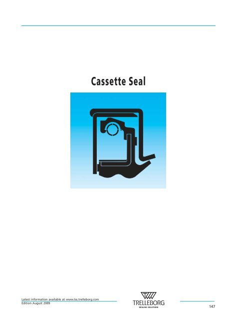
Cassette <strong>Seal</strong><br />
Latest information available at www.tss.trelleborg.com<br />
Edition August 2009<br />
147
148<br />
Latest information available at www.tss.trelleborg.com<br />
Edition August 2009
Cassette <strong>Seal</strong><br />
n CASSETTE SEAL<br />
n General<br />
The Cassette <strong>Seal</strong> has been developed to meet the everincreasing<br />
requirements of long service life, high functional<br />
reliability, environmental safety, simple handling and<br />
superior total economy.<br />
Cassette <strong>Seal</strong>s are fully enclosed seals with an integrated<br />
sealing system, that performs the function of oil seal, wear<br />
sleeve and dust protection in one unit. No extra<br />
components such as shaft sleeves or dirt protection are<br />
needed.<br />
Unique to all the Trelleborg <strong>Seal</strong>ing Solutions Cassette seals<br />
is that the sealing lip is fixed on the stationary part of the<br />
hardware. Because of this the sealing force is constant,<br />
independent of the rotary speed.<br />
Cassette seals consist of several individual features working<br />
together, built into one unit and for this reason they are<br />
called “Systems“.<br />
The TSS Cassette <strong>Seal</strong>s were originally designed at<br />
FORSHEDA AB in Sweden and sold under the trade name<br />
STEFA.<br />
n System 500<br />
10<br />
Oil side<br />
8<br />
1 2 3<br />
9<br />
Figure 51 System 500<br />
4<br />
Air side<br />
System 500, the original Unitized Wheel Hub <strong>Seal</strong> for<br />
heavy-duty vehicles, is designed for rotating hubs.<br />
The inner section of the System 500 is secured against the<br />
shaft. The outer section, press fitted into the wheel hub,<br />
rotates together with the hub around the inner section,<br />
creating a completely enclosed seal. Dirt and water, the<br />
major enemies of hub seals, are effectively kept at distance,<br />
7<br />
6<br />
5<br />
whilst the lubrication of the rubber lip remains intact. This<br />
decreases friction and increases seal life accordingly.<br />
The main features of the System 500 are:<br />
- The sealing (1) element is non-rotating, which means that<br />
the radial force is kept unchanged at various speeds.<br />
- The sealing surface (2) is in close contact with the wheel<br />
hub, which gives an excellent heat transfer.<br />
- The structure of the sealing counterface (3) has been<br />
chosen after several thousands of test hours. The position<br />
of the sealing lip ensures best lubrication.<br />
- The sealing lip (4) normally has bi-directional TURBOpattern<br />
(see page 150).<br />
- Integral prelubricated dust-sealing (5) functions.<br />
- The protruding conical part (6) of the case deflects<br />
heavier particles due to the centrifugal force.<br />
- The excluding lip (5) protects against water splash and<br />
finer particles.<br />
- Molded distance lugs (7) automatically locate the sealing<br />
element in the right position.<br />
- The lugs (7) are spaced and dimensioned to ensure the<br />
sealing lip has adequate lubrication.<br />
- The inner case (8) also protects the sealing lip from direct<br />
oil spray caused by taper roller bearings.<br />
The robust ribs (9) give:<br />
- a firm seat on the shaft<br />
- a smooth sliding during installation<br />
- a positive static seal even if one of the ribs is located on a<br />
defective shaft surface<br />
- The compression spring (10) maintains the radial force.<br />
The initial force exerted by the sealing element will in<br />
some applications reduce due to aging of the rubber<br />
exposed to heat, load or chemical action.<br />
- For such applications where the seal is exposed to dirty<br />
environment, i.e. off road use, the System 500 can be<br />
equipped with an additional specially developed dirt<br />
protection, the HRV seal.<br />
- In cases where the space does not allow the use of the<br />
HRV seal, the System 500HD, a derivative of System 500,<br />
can be used. It has the same outside dimensions, but an<br />
extra dust lip inside. Since the casing is identical to System<br />
500 it is readily available in the same sizes. Please contact<br />
you local Trelleborg <strong>Seal</strong>ing Solutions marketing<br />
company for more details.<br />
Latest information available at www.tss.trelleborg.com<br />
Edition August 2009<br />
149
Cassette <strong>Seal</strong><br />
n System 3000<br />
n System 5000<br />
Oil side<br />
Air side<br />
Oil side<br />
Air side<br />
Figure 52 System 3000<br />
Figure 53 System 5000<br />
System 3000 is specifically designed for rotating hubs on<br />
off-road machines in heavy duty applications, i.e. wet rice<br />
fields. The design offers significant improvements in<br />
providing improved ability to exclude water, dirt and dust<br />
for much longer time. Its ability to sustain eccentricities,<br />
over-pressure and shaft misalignments are equal to Radial<br />
<strong>Seal</strong>s.<br />
The System 3000, while based on System 500, features two<br />
sealing lips, equipped with compression springs, to provide<br />
excellent sealing performance and an additional dust lip.<br />
Mudbox-tests are showing more than doubled lifetime<br />
performance compared with the other system seals.<br />
The System 5000 is, like System 500 and System 3000, a fully<br />
enclosed seal however designed for rotating shafts. The<br />
System 5000 has the same features but the design has been<br />
inverted, i.e. the sealing element is fixed in the stationary<br />
housing and the casing components rotates with the shaft.<br />
The System 5000 is used to prevent oil from leaking out of<br />
a bearing housing, i.e. a differential pinion housing for rear<br />
axles on trucks, and at the same time preventing road dirt,<br />
salt and water splash to enter.<br />
The design is compact and integrates the necessary shaft<br />
counterface as well as the dirt exclusion. The dirt exclusion<br />
function consists of two rubber lips, one axial and one<br />
radial, the space between these filled with grease, and the<br />
rotating seal case, which acts as an effective deflector due<br />
to the centrifugal force.<br />
TURBO-pattern - Hydrodynamic sealing aids<br />
TURBO is the Trelleborg <strong>Seal</strong>ing Solutions designation of a<br />
range of hydrodynamic sealing aids supporting the sealing<br />
function. The hydrodynamic sealing aids are located on the<br />
air side of main sealing lip in the form of ribs or other<br />
geometrical figures of a variety of shapes. Optimum<br />
sealing conditions are attained when a thin film of<br />
lubricant is formed so that the lip does not come in<br />
contact with the sealing counterface. Such conditions are<br />
created by the TURBO-pattern, which brings about a<br />
pumping effect. The pumping effect starts at relatively<br />
low shaft speed, and is understood as the capacity of the<br />
seal lip to pump the medium to be sealed back from the air<br />
side to the medium side.<br />
150<br />
Latest information available at www.tss.trelleborg.com<br />
Edition August 2009
Cassette <strong>Seal</strong><br />
In order to avoid leakage at standstill or low speed, the<br />
TURBO-pattern includes a static edge, which provides a<br />
continuous contact line against the shaft. The frictional loss<br />
of the seals provided with TURBO-pattern is significantly<br />
lower than that caused by seals without hydrodynamic<br />
sealing aids. A lower friction does also allow higher shaft<br />
speeds, or provide longer service life.<br />
The Turbo pattern is available in three versions: Bidirectional,<br />
left hand or right hand rotation. The<br />
standard is bi-directional as most applications have<br />
alternating movement of the hub or shaft. If an<br />
application has rotation in one direction only, the<br />
corresponding left or right hand type can be specified.<br />
The direction of rotation is always defined as seen from the<br />
air side.<br />
width<br />
width<br />
width<br />
Medium<br />
System 500 System 3000 System 5000<br />
d2 H8<br />
d1 h8<br />
Figure 54<br />
Table XLII<br />
ID<br />
d 1<br />
Installation drawing<br />
System 500<br />
Standard dimensions<br />
OD Width System 3000<br />
System 5000<br />
d 2<br />
NBR HNBR FKM NBR HNBR FKM NBR HNBR FKM<br />
(TC 5)<br />
(TC 3)<br />
(TC 0)<br />
85 140 17 X X X<br />
90 130 17 X X X<br />
100 130 17 X X<br />
100 140 17 X X X<br />
110 140 17 X X X<br />
111 146 17 X X X<br />
120 160 17 X X X<br />
125 160 17 X X X<br />
128 164 17 X X X<br />
130 160 17 X X X X X X<br />
130 170 17 X X X<br />
135 165 17 X X X<br />
140 170 17 X X X<br />
143.3 190.5 16 X X<br />
145 175 17 X X X<br />
149.9 176 16 X X<br />
150 180 17 X X X<br />
155 190 17 X X X<br />
160 196 17 X X<br />
Latest information available at www.tss.trelleborg.com<br />
Edition August 2009<br />
151
Cassette <strong>Seal</strong><br />
ID<br />
d 1<br />
OD Width System 500<br />
d 2<br />
(TC 5)<br />
System 3000<br />
(TC 3)<br />
System 5000<br />
(TC 0)<br />
NBR HNBR FKM NBR HNBR FKM NBR HNBR FKM<br />
178 205 17 X X X<br />
187 230 17 X X X<br />
190 230 17 X X X<br />
320 360 19 X X<br />
Table XLIII<br />
Materials<br />
Standard material*<br />
TSS<br />
material code<br />
Standard<br />
metal case<br />
Standard<br />
spring<br />
NBR (75 Shore A) 4N063 Carbon steel Carbon steel<br />
HNBR (75 Shore A)<br />
4H063<br />
FKM (75 Shore A) 4V063 Carbon steel Carbon steel<br />
* Special grades and other materials (ACM, EACM, VQM) on request.<br />
Ordering example<br />
Due to various combinations (HRV-additional dirt seal +<br />
coating), please contact your Trelleborg <strong>Seal</strong>ing Solutions<br />
marketing company for ordering cassette seals.<br />
152<br />
Latest information available at www.tss.trelleborg.com<br />
Edition August 2009
Cassette <strong>Seal</strong><br />
n Material<br />
Metal case<br />
The cases are normally stamped of cold rolled steel sheet,<br />
EN 10 130 - Fe P04. The high demands on the metal cases;<br />
high surface finish, free from scratches etc., calls for<br />
production in special tools.<br />
Compression spring<br />
For the spring, spring steel SS14 1774 - DIN 17223 - is<br />
normally employed. If resistance to corrosion is required,<br />
stainless steel SS 14 2331 - DIN 1.4301 - is used.<br />
<strong>Seal</strong>ing element<br />
The material of the sealing element must be selected<br />
according to the working conditions of the seal and the<br />
environmental conditions.<br />
Some of the requirements associated with environmental<br />
considerations are:<br />
- good chemical resistance<br />
- good resistance to heat and low temperature<br />
- good resistance to ozone and weathering<br />
The functional demands include:<br />
- high resistance to wear<br />
- low friction<br />
- low compression set<br />
- good elasticity<br />
In addition, cost considerations make ease of process a<br />
desirable feature.<br />
No material is available today, which satisfies all these<br />
requirements. The choice of material is therefore always a<br />
compromise between the relative significance of the<br />
factors involved.<br />
Trelleborg <strong>Seal</strong>ing Solutions has succeeded in developing a<br />
Nitrile Rubber compound (NBR), which exhibits good allround<br />
properties, and for this reason it is the compound<br />
most commonly used.<br />
The materials normally used for the sealing element are:<br />
Nitrile Rubber (NBR), Hydrogenated Nitrile Rubber (HNBR)<br />
and Fluorinated Elastomers (FKM).<br />
The additional dirt seal is normally made of Nitrile Rubber.<br />
Nitrile Rubber is the basis material for cassette seals, as it<br />
covers most standard application requirements for general<br />
oil- and grease resistance. It is from function and cost<br />
aspects the best choice when temperature is not excessively<br />
high.<br />
Nitrile can be used up to 125°C in non-aggressive oils.<br />
However for long term use, or in aggressive oils, service<br />
temperature is reduced to 80°C.<br />
Nitrile generally has good mechanical properties and the<br />
material used for cassette seals is optimized for best heat<br />
and abrasion resistance.<br />
Hydrogenated Nitrile Rubber is a further development of<br />
NBR, where the chemical double bonds in the polymer<br />
molecules are saturated with hydrogen. Since the double<br />
bonds of NBR are sensitive to heat and ozone, the HNBR<br />
will be superior to NBR in heat, ozone and weather<br />
resistance. It can generally be used up to 150°C in nonaggressive<br />
media, however for long term use maximum<br />
service temperature is 120°C.<br />
The HNBR for the cassette seal is fully saturated and thus<br />
well suited for use in aggressive oils. The temperature<br />
should however be limited at 120°C. As saturated HNBR<br />
cannot be vulcanized with sulfur, the material has<br />
resistance to most hypoid oils up to about 120°C for long<br />
term use.<br />
Low friction and high abrasion resistance are additional<br />
typical features.<br />
Fluorinated Elastomers gives peak performance regarding<br />
heat and chemical resistance. They can be used up to 200°C<br />
for long term and are generally very resistant to oil, grease<br />
and fuels. Ozone and weather resistance is outstanding.<br />
Mechanical and low temperature properties are however<br />
lower compared to Nitrile. Thus Fluoroelastomers should<br />
be considered only when the material properties are fully<br />
used. Some oil additives like amines and high pH-values<br />
may damage Fluoroelastomers, when used at high<br />
temperatures.<br />
Temperature resistance<br />
Increasing temperature accelerates the aging of rubber,<br />
the elongation decreases, and the compression set<br />
increases and finally the material becomes hard and<br />
brittle. Cracks at the sealing edge are a typical indication<br />
that the seal has been exposed to excessively high<br />
temperature. The aging of the rubber has appreciable<br />
significance on the useful life of the seal. It can generally<br />
be said that a temperature increase of 10°C (in air) will half<br />
the theoretical useful life of the rubber. Low temperatures<br />
are generally not a big problem since the seals themselves<br />
generate heat by friction when rubbing against another<br />
surface. If the seal has been chilled down, its original<br />
properties will return as soon as it is warmed up again.<br />
Some leakage may however arise during the start-up<br />
phase, before rubber material is softened by friction heat.<br />
Latest information available at www.tss.trelleborg.com<br />
Edition August 2009<br />
153
Cassette <strong>Seal</strong><br />
Temperature limits for seals in typical hypoid oils,<br />
long time use contra short duration load.<br />
-100<br />
NBR<br />
-40 80 150<br />
HNBR<br />
-30<br />
120 170<br />
FKM<br />
-30<br />
100 150 250<br />
-50 0 +50 +100 +150 +200 +250<br />
Temperature °C<br />
= working period of 10.000 hrs<br />
= test against specified oil required<br />
= only for short duration load<br />
Figure 55 Temperature recommendations in typical<br />
hypoid oils<br />
The temperature limits for the standard materials in hypoid<br />
oils are illustrated in figure above. They should only be<br />
regarded as approximate, since the oil type and the time of<br />
exposure also affect the materials. The temperature ranges<br />
within the shaded areas in the illustrations are<br />
temperatures that can be allowed only for certain<br />
periods of time. The higher the temperature, the shorter<br />
the period of time. At low temperatures, time has no<br />
influence on aging.<br />
However, seals are not often working in air as only<br />
medium, but they are also affected by other media.<br />
Temperature limits in combination with other oils and<br />
media can be obtained from your local Trelleborg <strong>Seal</strong>ing<br />
Solutions marketing company.<br />
Oil resistance<br />
Innumerable types of oils are available on the market and<br />
each of these has a different effect on the rubber. In<br />
addition, a given type of oil from different manufacturing<br />
may have a different influence.<br />
The additives in the oil generally affect the rubber. This is<br />
the case with hypoid oil, which contains sulfur. Since sulfur<br />
is used as vulcanizing agent for Nitrile rubber, the sulfur<br />
additive in the oil acts as a vulcanizing agent at<br />
temperatures above +80°C. As a result of this secondary<br />
curing, Nitrile rubber will rapidly become hard and brittle.<br />
Hydrogenated Nitrile and Fluorinated rubbers, which are<br />
not vulcanized with sulfur, can therefore be used for this<br />
type of oil, even though the operating temperature may<br />
not require these.<br />
Oxidized oils represent another example illustrating the<br />
difficulty of tabulating the oil resistance of rubber<br />
materials. These oils are oxidized during operation and<br />
their properties will therefore change substantially.<br />
Due to the above, no detailed information is given about<br />
resistance to certain types of oils. In case of questions or<br />
doubt, it is advisable to contact your local Trelleborg<br />
<strong>Seal</strong>ing Solutions marketing company who have access to<br />
the many years of in-house testing made by FORSHEDA AB.<br />
Additional testing can be carried out in specific oil types<br />
provided a sufficient sample is available.<br />
Chemical resistance<br />
Since the Cassette seals are normally exposed to oil or<br />
grease, and not other chemicals, tables for chemical<br />
resistance to different media are not included. For<br />
guidelines about chemical resistance, please look under<br />
“Radial Oil <strong>Seal</strong>s“ or contact your local Trelleborg <strong>Seal</strong>ing<br />
Solutions marketing company.<br />
n Application<br />
System 500, 3000 and 5000<br />
For the System 500, 3000 and 5000, requirements on the<br />
shaft finish and hardness are less stringent in comparison<br />
with traditional radial shaft seals. A simple fine turning<br />
operation gives an adequate surface on the shaft as well as<br />
for the housing bore. Diameter tolerances and finish values<br />
are shown in Figure 61 and 60.<br />
As the sealing elements have built in counterfaces of their<br />
own, no wear on the shaft itself will occur and<br />
consequently no hardening of the shaft is necessary.<br />
Suitable lead in chamfers facilitates the installation of the<br />
seal.<br />
154<br />
Latest information available at www.tss.trelleborg.com<br />
Edition August 2009
D H8<br />
Cassette <strong>Seal</strong><br />
2,0<br />
15°<br />
3,2<br />
5,0<br />
2,5<br />
15°<br />
d h8<br />
2,0<br />
Figure 56<br />
System 500 in wheel hub application<br />
2,0<br />
15°<br />
5,0<br />
2,5<br />
15°<br />
3,2<br />
d h8<br />
2,0<br />
D H8<br />
Figure 57<br />
System 5000 in pinion application<br />
Latest information available at www.tss.trelleborg.com<br />
Edition August 2009<br />
155
Cassette <strong>Seal</strong><br />
Shaft run out<br />
Shaft run out should as far as possible be avoided or kept<br />
within a minimum. At higher speeds there is a risk that the<br />
inertia of the sealing lip prevents it from following the<br />
shaft movement. The seal must be located next to the<br />
bearing and the bearing play is maintained at the lowest<br />
possible value.<br />
Axial movement<br />
Axial movement, inclusive what can be considered as<br />
normal bearing play, should be within ± 0.1 mm. The<br />
Cassette seal will function at larger movements, however<br />
this may cause a larger wear on support lugs and in the end<br />
shorter lifetime.<br />
Shaft run out<br />
(mm)<br />
0.3<br />
0.2<br />
0.1<br />
0<br />
Figure 58<br />
NBR-HNBR-FKM<br />
1000 2000 3000 4000 5000 6000 7000 (rpm)<br />
Shaft speed<br />
Permissible run out of the shaft<br />
Eccentricity<br />
Eccentricity between shaft and housing bore centers<br />
should be avoided in order to eliminate unilateral load of<br />
the lip.<br />
Eccentricity<br />
Figure 59<br />
(mm)<br />
0.4<br />
0.3<br />
0.2<br />
0.1<br />
0<br />
50<br />
100 150 200 250<br />
25 75 125 175 225 275<br />
Shaft diameter<br />
Permissible eccentricity<br />
(mm)<br />
Shaft misalignment<br />
Shaft misalignment should as far as possible be avoided or<br />
kept at a minimum, max. 0.25 mm.<br />
Pressure<br />
Any difference in pressure from one side of the seal to the<br />
other should be avoided. Since the seal is developed for<br />
ventilated applications, a pressure difference will in the<br />
end lead to a decreased lifetime or leakage.<br />
In some applications, a pressure difference up to 0.05 MPa<br />
could be accepted, but tests should be carried out for each<br />
case.<br />
Speed<br />
The permissible speed of rotation at sealing point for the<br />
various seal designs stated below, assumes normal running<br />
conditions, e.g. oil retention and no pressure differential<br />
across the seal.<br />
Type of <strong>Seal</strong><br />
max. Surface Speed (m/s)<br />
System 500 10<br />
System 3000 4<br />
System 5000 15<br />
Start-/Operating torque<br />
Due to transferred assembly forces inside the Cassette seal,<br />
the Cassette seal absorbs higher torque than a standard<br />
radial seal. See also the Installation part.<br />
HRV - Additional dirt seal<br />
The HRV seal is an all-rubber seal. It is designed for use as<br />
complementary seal for the System 500, in dirty<br />
applications such as off-road. The main sealing is against<br />
small particles such as dust, but also dirt and splash. Since<br />
the sealing action is axially, it can absorb some axial<br />
displacement.<br />
The HRV seal is bonded directly to the outer case of the<br />
System 500. The design is similar to the FORSHEDA V-ring<br />
with a body and a flexible conical shaped sealing lip with<br />
an integral resilient “hinge“.<br />
The HRV seal rotates, due to the outer case being press<br />
fitted into the bore, and seals axially against a stationary<br />
counter face. During rotation the sealing lip rubs against<br />
the counterface under a contact pressure calculated to<br />
achieve a sealing function. The HRV seal also operates as a<br />
deflector ring, and its centrifugal action contributes to a<br />
good sealing function. Due to the centrifugal force, the<br />
contact pressure of the lip decreases with increase in speed.<br />
The contact pressure also varies with the fitted width.<br />
156<br />
Latest information available at www.tss.trelleborg.com<br />
Edition August 2009
Cassette <strong>Seal</strong><br />
The counterface for the HRV seal can consist of a suitable<br />
surface on the existing hardware or a steel casing adapted<br />
to suit the specification for the seal counterface.<br />
The HRV seal:<br />
- seals against outer medium like dirt and dust<br />
- has a deflecting function due to the centrifugal force<br />
The requirements on the counterface against which the<br />
sealing lip works are rather low. The requirements are<br />
more or less determined by the medium to be sealed. A<br />
finish-turned, polished surface with a surface roughness of<br />
Ra 1.6 to 2.0 μm is normally adequate. For sealing against<br />
liquid and dirt, Ra 0.8 to 1.6 μm is recommended. However,<br />
the character of the surface is of greater importance than<br />
the actual surface roughness value. For turned surfaces, it is<br />
recommended to buff the surface with fine emery cloth to<br />
remove any sharp peaks, which could tear the rubber<br />
surface apart and destroy the sealing function and shorten<br />
seal life time.<br />
It is also necessary to ensure that the counterface is<br />
perpendicular to the shaft, flat and free from scratch<br />
marks and other damage within the sealing area. This is<br />
especially important when sealing fluids and fine particles.<br />
To achieve the full effect of the deflector action, the HRV<br />
seal should be designed in a relatively open space.<br />
The fitted width dimension will be stated on the<br />
corresponding product drawing.<br />
2,0<br />
Fitted width<br />
of HRV seal<br />
n Installation<br />
As the Cassette <strong>Seal</strong> incorporates all functions as seal, shaft<br />
counterface and dust protection, there is no need for extra<br />
components such as exchangeable shaft sleeves or dirt<br />
protection.<br />
This means fewer parts to stock and handle.<br />
When handling and fitting traditional shaft seals there is<br />
always a risk of damaging the shaft surface or sealing lips<br />
and of improper installation. As the Cassette seal is fully<br />
enclosed the vital sealing components cannot be touched<br />
or damaged during the installation.<br />
System 500 and System 3000<br />
When the bearing has been installed the seal is simply<br />
pressed into the hub bore. The seal shall be oriented with<br />
the side marked “oil side“ facing the interior of the hub. It<br />
is recommended to oil the inside rubber covered surface of<br />
the seal and also the shaft, to decrease the force necessary<br />
for assembly. If the Cassette seal is equipped with the<br />
additional dirt protection this shall be greased prior to<br />
fitting. The complete hub is then placed over the axle<br />
spindle. Normally the locking nuts for the bearing are used<br />
to drive the hub home. The Cassette seal automatically<br />
takes the right position on the shaft and no axial support is<br />
required provided no over pressure is built up during<br />
operation.<br />
During the start-up phase, some leakage of grease as well<br />
as smoke formation may occur. This is a result of the<br />
generation of frictional heat between the metal cases and<br />
support lugs, and does not influence the function and<br />
service life of the seal.<br />
If the seal has been misaligned during installation, or<br />
jammed against the bore, this may lead to the support lugs<br />
being too close to the metal case. This may mean the lugs<br />
are worn out or torn away at the start-up phase. The seal<br />
must in these cases always be replaced before start-up.<br />
When repairing of the wheel hub becomes necessary, a<br />
new seal shall always be installed.<br />
Figure 60<br />
System 500 with HRV seal<br />
Latest information available at www.tss.trelleborg.com<br />
Edition August 2009<br />
157
Cassette <strong>Seal</strong><br />
System 5000<br />
The System 5000 seal must be installed onto a shaft or a<br />
sleeve by a special assembly tool. The seal shall be oriented<br />
with the side marked “oil side“ facing the inside of the<br />
gearbox. The shaft must then be assembled so the oil side<br />
of the seal is entering the housing bore.<br />
If the shaft is hollow, the assembly tool should be designed<br />
with a guiding column.<br />
For pinion applications on trucks, when a separate end<br />
carrier is used, the seal is simply pressed onto the end<br />
carrier in a first step of assembling. The end carrier is then<br />
entering the splines on the pinion shaft and then a locking<br />
nut is used to drive the end carrier and the seal into the<br />
right position.<br />
The force required to assemble a System 5000 seal onto the<br />
shaft is between 20 to 50 kN, while assembly into the<br />
housing bore requires about 1.0 kN. The value of assembly<br />
force depends on surface structure for shaft resp. housing<br />
bore as well as the tolerances. It is recommended to oil the<br />
outer rubber covered surface of the seal and also the<br />
housing bore, to decrease the force necessary for assembly.<br />
During the start-up phase, eventually some leakage of<br />
grease and smoke formation may occur. This is a result of<br />
the generation of frictional heat between the metal cases<br />
and the support lugs of rubber, and does not influence on<br />
the function and service life of the seal.<br />
If the seal is jammed or damaged in some way during<br />
installation, the seal must be replaced before start up.<br />
If the construction is disassembled for any reason, a new<br />
seal should be installed.<br />
Further instructions for assembling can be found on<br />
separate assembly instruction sheets available from your<br />
local Trelleborg <strong>Seal</strong>ing Solutions marketing company.<br />
Storage<br />
As the service life of bearings and other machine parts<br />
depends on how well the seals perform, seals should be<br />
handled with caution. Unfavorable storage conditions or<br />
improper handling will most likely lead to a change of their<br />
physical properties. This can lead to a shortening of life, or<br />
failure, for example as a result of hardening or softening,<br />
cracking or other surface damages. These changes can be<br />
the result of one particular factor or a combination of<br />
factors, like oxygen, ozone, heat, light, moisture, solvents<br />
etc. Storing the seals under load can lead to permanent<br />
deformation of the elastomer. On the other hand, properly<br />
stored elastomer products retain their properties for<br />
several years.<br />
As the sensitive sealing lips and counter faces are well<br />
protected inside the Cassette seal casing, there is less risk of<br />
mechanical damages and influence of dirt and dust in<br />
comparison to many other seal types.<br />
Cleaning<br />
If cleaning of Cassette seals is necessary, use a damp duster<br />
and allow the seals to dry off at room temperature.<br />
Solvents, sharp-edged objects and abrasives should not be<br />
used.<br />
Dismantling and replacement<br />
As all the necessary functions are integrated in the Cassette<br />
seal the complete sealing arrangement is renewed. The<br />
shaft to be sealed is unaffected by wear and once it has<br />
been cleaned and possible corrosion and dirt have been<br />
removed a new seal can be fitted again.<br />
The Cassette <strong>Seal</strong> may be provided with a sealant on the<br />
metal casing when it is installed into the housing. Take care<br />
that the sealant do not flow into the seal or is smeared<br />
onto the rubber surface, as this may impede the function<br />
of the seal. The sealant can reduce the risk of static leakage<br />
due to small imperfections on the surface.<br />
158<br />
Latest information available at www.tss.trelleborg.com<br />
Edition August 2009