SMART PULLEY
SMART PULLEY
SMART PULLEY

Create successful ePaper yourself
Turn your PDF publications into a flip-book with our unique Google optimized e-Paper software.
<strong>SMART</strong> <strong>PULLEY</strong><br />
(PHOTOGATE + <strong>SMART</strong> <strong>PULLEY</strong> ATTACHMENT)<br />
DESCRIPTION D0386<br />
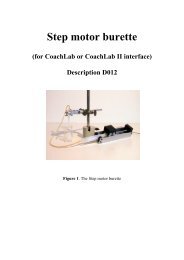
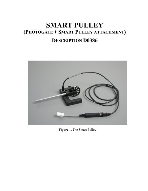
Figure 1. The Smart Pulley
Short Description<br />
The Smart Pulley consists of a<br />
photogate and smart pulley<br />
attachment.<br />
The photogate has a narrow,<br />
infrared beam and fast response<br />
time, which provide very accurate<br />
signals for timing. When the<br />
infrared beam between the source<br />
and detector is blocked, the<br />
output of the photogate is low,<br />
and the light-emitting diode<br />
(LED) on the photogate goes ON.<br />
When the beam is not blocked,<br />
Figure 2. The photogate<br />
the output is high and the LED is<br />
OFF. The use of infrared makes the sensor relatively insensitive to room lighting.<br />
The smart pulley attachment connects to the photogate by using the metal rod. Place<br />
the rod though the hole in the photogate and move the pulley into position so that the<br />
rod can be threaded into it. Tighten up the rod so that the pulley is held firmly against<br />
the photogate. When properly positioned, the spokes of the pulley will block the<br />
infrared beam of the photogate each time the spokes pass by.<br />
The Smart Pulley is delivered with a BT plug and can be connected to the following<br />
interfaces:<br />
• CMA ULab, CoachLab, CoachLab II, UIA/UIB boards through the Measuring<br />
Console (via 0520 adapter) and SMI (via 0520 adapter);<br />
• Texas Instruments CBL and CBL2 dataloggers;<br />
• Vernier LabPro datalogger.<br />
There is an adapter (art. 0520) to connect sensors with BT-plugs to 4-mm inputs.<br />
The name of the Smart Pulley in the sensor library of Coach 5 program is<br />
Smart Pulley (0386) (CMA)(0..2000).<br />
Attention: Do not use the sensor Smart Pulley (4mm) (CMA)(0..1000)<br />
Suggestion for experiments<br />
Use of the photogate independently<br />
This general-purpose photogate can be used for a wide variety of experiments:<br />
- measuring the acceleration due to gravity (use a transparent piece of plastic with<br />
stripes at regular intervals, which can be allowed to fall through the photogate);<br />
2
- studying the swing of a pendulum;<br />
- measuring the speed of a rolling object;<br />
- timing the period of a rotating object<br />
Owing to the use of infrared light, the light gate is not suitable for counting drops.<br />
Use of the smart pulley<br />
The pulley can not determine the direction or change in direction. The pulley is<br />
therefore only useful where the movement is in one direction, as in:<br />
- Atwood's experiment,<br />
- a model boat being pulled<br />
along in water,<br />
- a vehicle on an air track.<br />
By connecting a belt<br />
between the pulley and a<br />
rotating object, rotations can<br />
also be investigated.<br />
When the pulley is used in<br />
Event-based measurement<br />
activity, the pulley must be<br />
connected to the counter<br />
input and the negative going<br />
flanks (i.e. when the sensor moves Figure 3. Result of Atwood's experiment.<br />
from light to dark) are counted.<br />
..<br />
The pulley settings<br />
The pulley has a V groove. The circumference of the wheel measured in the V groove<br />
is 0.15 m. On the edge of the groove the circumference is 0.16 m.<br />
The movement of a cord as the pulley revolves is then to some extent dependent upon<br />
the thickness of the cord.<br />
Calibration can be done by measuring the circumference with the cord that is going to<br />
be used and dividing the total by ten (10 spokes). We term this value the step size. This<br />
means that each time that a new gap in the pulley is reached there has been movement<br />
of this distance since the start of the last gap.<br />
In the same way, event-based measurement can be prepared to measure with other<br />
settings for example for angular movements. When angular measurements are made,<br />
the step size is 2*ð/10 radians (0.628 rad).<br />
When the pulley is used for the measurement of rotation of<br />
objects, the step size of the original angle can be determined as<br />
follows:<br />
2π<br />
Θ = 10<br />
R<br />
∗<br />
R<br />
pulley<br />
object<br />
3
Technical data<br />
Output Dark: 0.03V<br />
Light: 4.98V<br />
Detector rise time<br />
Detector fall time<br />
Parallax error<br />
Power requirements<br />
Infrared source<br />
Diameter of Pulley<br />
Circumference of<br />
pulley<br />
< 500 ns<br />
< 50 ns<br />
For an object passing within 1 cm of the detector, with a<br />
velocity less than 10 m/s, the difference between true and<br />
effective length is less than 1 mm.<br />
5 V DC at 45 mA<br />
Peak at 880 nm<br />
In groove = 0.02387 m<br />
On edge = 0.02546 m<br />
In groove = 0.15 m<br />
On edge =0.16 m<br />
Step size Angle = 0.6283 rad = 36°<br />
Distance = 0.015 m to 0.016 m, dependent upon the thread<br />
used.<br />
10 pulses (steps) per revolution<br />
Connection<br />
BT (British Telecom) plug<br />
This product is to be used for educational purposes only. It is not appropriate for industrial,<br />
medical, research, or commercial applications.<br />
CENTRE FOR MICROCOMPUTER APPLICATIONS<br />
Kruislaan 404, 1098 SM Amsterdam, The Netherlands<br />
Fax: +31 20 5255866, e-mail: cma@science.uva.nl, http://www.cma.science.uva.nl<br />
4<br />
Rev. 2002-06-03