Performance Evaluation of a 1.2 KW Fuel Cell - satnac
Performance Evaluation of a 1.2 KW Fuel Cell - satnac
Performance Evaluation of a 1.2 KW Fuel Cell - satnac

You also want an ePaper? Increase the reach of your titles
YUMPU automatically turns print PDFs into web optimized ePapers that Google loves.
<strong>Performance</strong> <strong>Evaluation</strong> <strong>of</strong> a <strong>1.2</strong> kW <strong>Fuel</strong> <strong>Cell</strong><br />
Thapelo Pholo and Pr<strong>of</strong>. Christo Piennar*<br />
Department <strong>of</strong> Applied Electronics and Electronic Communication<br />
Vaal University <strong>of</strong> Technology, Vanderbijlpark, Gauteng, South Africa<br />
Tel: +27 16 950-9074 VoIP 7701#, Fax: +27 16 950 3535<br />
Email: {20214146pholo, christop}@vut.ac.za<br />
Abstract – <strong>Fuel</strong> cell (FC) systems have emerged as a<br />
promising alternative to conventional power<br />
technologies over the past decade owing to their high<br />
efficiency, low aggression to the environment, excellent<br />
dynamic response and superior reliability and<br />
durability. In this paper, the results <strong>of</strong> the evaluation <strong>of</strong><br />
a <strong>1.2</strong> kW FC including the electrochemical model are<br />
reported. The FC stack dynamic simulation using<br />
SIMULINK TM and the experimental results are also<br />
presented. In the end the dynamic behaviour and<br />
modelling results are used to predict the output voltage,<br />
power, efficiency and the polarisation curves <strong>of</strong> the FC.<br />
two porous gas diffusion electrodes, a cathode and an anode, see<br />
Figure 1. In a typical FC, gaseous fuels are continuously fed to<br />
the anode and an oxidant is continuously fed to the cathode.<br />
Basic electrochemical reactions take place at the electrodes to<br />
produce electric current. The porous electrodes provide a surface<br />
site where gas/liquid ionization or de-ionization reactions take<br />
place as well as conduction <strong>of</strong> ions.<br />
Index terms- Proton exchange membrane (PEM), <strong>Fuel</strong><br />
<strong>Cell</strong> (FC), Modeling, Simulink, <strong>Performance</strong> <strong>Evaluation</strong><br />
I. INTRODUCTION<br />
The global energy consumption is rising steadily and a lot<br />
<strong>of</strong> pressure is put on electricity utilities to increase their<br />
generation capacity. In South Africa, most <strong>of</strong> the power<br />
generated is from coal and an increase in power generation<br />
is an increase in greenhouse emissions into the atmosphere.<br />
The development <strong>of</strong> energy systems that generate power<br />
efficiently and cleanly is becoming more and more<br />
important for telecommunications [1]. This has shifted the<br />
attention towards the use <strong>of</strong> FC systems globally. The use<br />
<strong>of</strong> these systems is expected to become more widespread<br />
owing to better power quality, reliability, portability, lack <strong>of</strong><br />
moving parts, silent operation and low adverse effects on<br />
the environment [2].<br />
<strong>Fuel</strong> cells are electrochemical devices that convert<br />
chemical energy <strong>of</strong> a fuel into electricity at high efficiency<br />
without combustion. They are viewed as viable power<br />
sources for many applications including automobiles,<br />
distributed power generation and portable electronics.<br />
Among the various types <strong>of</strong> hydrogen-oxygen fuel cells,<br />
the phosphoric acid fuel cell is the most mature and<br />
advanced, however the proton exchange membrane (PEM)<br />
fuel cells are the most attractive for residential and<br />
telecommunications use due to its low operating<br />
temperature and fast start up characteristics.<br />
As part <strong>of</strong> the FC research project at the Vaal University<br />
<strong>of</strong> Technology (VUT) in Vanderbijlpark, South Africa,<br />
modelling and testing <strong>of</strong> various FC stacks capabilities is<br />
part <strong>of</strong> an ongoing process in the development <strong>of</strong> FC<br />
technologies and hence the work presented in this paper.<br />
II. FUEL CELL POWER SYSTEM<br />
A FC stack consists <strong>of</strong> a number <strong>of</strong> cells referred to as the<br />
membrane electrode assembly (MEA) sandwiched between<br />
Figure 1. A basic schematic <strong>of</strong> a <strong>Fuel</strong> <strong>Cell</strong> structure [3].<br />
A FC power system mainly consists <strong>of</strong> a FC stack which<br />
determines the output voltage while current is determined by the<br />
active cell area <strong>of</strong> the cells. Other parts <strong>of</strong> a FC system include<br />
the pumps and blowers, compressors, cooling systems, power<br />
conditioning unit and a fuel processing unit (reformer) which is<br />
needed only if the fuel does not use pure hydrogen.<br />
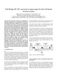
Figure 2. Block diagram <strong>of</strong> a FC power plant
A simplified schematic <strong>of</strong> the FC system is shown in Figure<br />
2 above. A controller is also needed to control the parts <strong>of</strong><br />
the system. A control and monitoring s<strong>of</strong>tware may be<br />
incorporated into the whole system.<br />
III. PRINCIPLES AND MODELING<br />
A. Principles <strong>of</strong> Operation<br />
In a FC, two half cell reactions take place simultaneously,<br />
at the anode an oxidation reaction and a reduction reaction<br />
at the cathode. These reactions make up the total oxidationreduction<br />
(redox) reaction <strong>of</strong> the FC and the by-product<br />
water. Electrical energy is obtained from the FC only when<br />
a reasonable current is drawn. When dealing with chemical<br />
energy, the Gibbs free energy and enthalpy are <strong>of</strong>ten used.<br />
In FCs, change in Gibbs free energy <strong>of</strong> formation is<br />
considered, as this change is responsible for the energy<br />
released. This change is the difference between the free<br />
energy <strong>of</strong> the products and the reactants, as shown in<br />
equation 1 [4].<br />
∆ G f = G f products – G f reactants (1)<br />
where:<br />
∆ G f<br />
change in Gibbs free energy<br />
In a FC using hydrogen and oxygen as fuel and oxidant<br />
respectively, for each molecule <strong>of</strong> hydrogen used, two<br />
electrons are released and passed through the external<br />
circuitry and through the load as electricity. The by-product<br />
water results from the recombination <strong>of</strong> the electrons and<br />
protons together with oxygen. Heat is also generated. The<br />
charge that flows per mole <strong>of</strong> hydrogen consumed is<br />
therefore:<br />
-2N A e = -2F (2)<br />
where:<br />
Avogadro’s number<br />
-e charge on an electron<br />
F the Faraday’s constant (96 485 C/mole)<br />
E voltage in Volts<br />
N A<br />
If E is the voltage <strong>of</strong> the cell, then the energy required to<br />
move this charge around a circuit is:<br />
Electrical work done = charge x voltage<br />
= -2FE Joules (3)<br />
Assuming the FC system was totally reversible, this work<br />
would be equal to ∆ G f such that:<br />
∆ G f = -2FE (4)<br />
Equation (4) can then be re-arranged to equation (5). This is<br />
an expression that gives the Electromotive Force (EMF) <strong>of</strong><br />
the cell. This fundamental equation gives the open circuit<br />
voltage (OCV) <strong>of</strong> the FC and assumes that the FC has no<br />
losses (i.e. 100 % efficiency) and that it is fuelled by<br />
hydrogen and oxygen at standard temperature and pressure.<br />
E<br />
− ∆Gf<br />
2F<br />
= V (5)<br />
And from Table 1, the E can be calculated.<br />
Table 1. ∆ G f for the reaction <strong>of</strong> H 2 O and O 2 at various<br />
temperatures.<br />
Form <strong>of</strong> H 2 O<br />
Product<br />
Temperature<br />
( ◦ C)<br />
∆G f<br />
(KJmol -1 )<br />
Liquid<br />
Liquid<br />
Gas<br />
Gas<br />
Gas<br />
Gas<br />
Gas<br />
Gas<br />
Gas<br />
25<br />
80<br />
80<br />
100<br />
200<br />
400<br />
600<br />
800<br />
1000<br />
-237.2<br />
-228.2<br />
-226.1<br />
-225.2<br />
-220.4<br />
-210.3<br />
-199.6<br />
-188.6<br />
-177.4<br />
The negative sign in the table means that energy is released.<br />
E<br />
− ∆Gf<br />
2F<br />
= V<br />
−<br />
E =<br />
3<br />
( − 237.2 × 10 )<br />
2<br />
= <strong>1.2</strong>29 V<br />
( 96485)<br />
An analysis <strong>of</strong> the FC reaction shows that the OCV <strong>of</strong> the FC<br />
shown from the result above <strong>of</strong> <strong>1.2</strong>29 V is achievable. This OCV<br />
is also known as the ideal standard potential (E o ) and is only<br />
theoretical because it does not take into account the losses<br />
incurred by the FC. When oxygen is supplied from the air, it is<br />
equivalent to supplying it at a lower pressure. This is taken into<br />
account by using the Nernst equation. This is described in detail<br />
by equation (7).<br />
The electrochemical model can be used to predict the dynamic<br />
behaviour <strong>of</strong> the FC stack. The electrochemical equations <strong>of</strong> the<br />
FC are given by:<br />
At the Anode:<br />
At the Cathode:<br />
H 2<br />
+ −<br />
2<br />
→2H<br />
+ e<br />
(6)<br />
+ −<br />
H + 2e<br />
+ 1 O2<br />
→ H<br />
2O<br />
+ heat<br />
2<br />
2 (7)<br />
Overall reaction:<br />
H 1 O → H O + heat<br />
(8)<br />
2<br />
+<br />
2<br />
2<br />
2<br />
The amount <strong>of</strong> hydrogen needed to meet the load and the amount<br />
<strong>of</strong> oxygen needed to maintain the reaction are determined by<br />
equations (6) and (7) respectively, while equation (8) gives the<br />
amount <strong>of</strong> water produced.
The actual cell potential <strong>of</strong> a single cell however in<br />
practice is lower than the voltage given in equation (5)<br />
because <strong>of</strong> the irreversible losses in voltage. The losses<br />
which are called polarisation or overvoltage originate from<br />
three principal sources: 1) activation polarisation, 2) ohmic<br />
polarisation and 3) concentration polarisation. This actual<br />
output voltage can be defined as follows:<br />
V<br />
FC<br />
where:<br />
= E −V<br />
−V<br />
−V<br />
(9)<br />
E<br />
nernst<br />
nernst<br />
≡<br />
act<br />
ohmic<br />
conc<br />
Thermodynamic potential<br />
Activation potential due to the three phase<br />
interface<br />
Ohmic potential due to resistance to flow <strong>of</strong><br />
ions<br />
Concentration polarisation due to a decrease<br />
in concentration <strong>of</strong> the reactants at the<br />
interface<br />
And for n cells connected in series forming a stack, the<br />
voltage, V stack , can be calculated as follows:<br />
inductor constitute the dynamic portion <strong>of</strong> the electric circuit<br />
model.<br />
Although the basic concept <strong>of</strong> FCs is quite simple, creating new<br />
designs and optimising their performance takes serious work and<br />
a mastery <strong>of</strong> several technical areas [6]. The dynamic modeling<br />
and the response prediction is necessary in order to evaluate the<br />
FC response and the performance behaviour on parameters such<br />
as hydrogen consumption, efficiency and output power <strong>of</strong> the<br />
stack [7].<br />
The electrical circuit model as well as equation (9) was used to<br />
simulate a model <strong>of</strong> the FC to give the output resembling the<br />
curves in Figures (9) and (10). The simulation program has been<br />
developed within the Matlab programming environment, using<br />
both the Matlab programming language and Simulink. Equation<br />
(9) forms the basis <strong>of</strong> all parameters that are analysed in Matlab<br />
for the FC. Examples <strong>of</strong> the script files used to produce the<br />
polarisation curve and curves <strong>of</strong> Figures 9, 12 and 14 can be<br />
found in [8] and [9] respectively.<br />
IV. EXPERIMENTAL<br />
The work presented here was carried out with Nexa TM power<br />
module from Ballard Power Systems Inc. at the Vaal University<br />
<strong>of</strong> Technology. The power module is shown in Figure 4 below.<br />
V stack = n.V FC (10)<br />
B. Modelling and Simulation<br />
<strong>Fuel</strong> cells are <strong>of</strong>ten analysed from an electrochemical<br />
perspective and hence yields many mathematical models<br />
that are important for improving the design <strong>of</strong> FC<br />
components as well as determining the optimal operating<br />
conditions [4].<br />
The static behaviour <strong>of</strong> the FC as shown by equations (6)<br />
to (8) can be used to develop an equivalent electrical circuit<br />
model shown in Figure 3 [5].<br />
Figure 4. A <strong>1.2</strong> <strong>KW</strong> PEM Nexa TM FC<br />
Figure 3. FC electrical circuit model<br />
In the circuit model in Figure 3, the diode, two transistors<br />
and a resistor model the static model. The diode models the<br />
activation polarisation with its principle <strong>of</strong> the potential<br />
barrier which inhibits the migration <strong>of</strong> charge carriers<br />
across the PN-junction. The ohmic polarisation is modelled<br />
by the parasitic resistances <strong>of</strong> the diode. The two transistors<br />
and the resistor form a current limiting circuit that models<br />
the concentration polarisation while the capacitor and an<br />
The Nexa system provides up to 1200W unregulated DC power<br />
at a nominal output voltage <strong>of</strong> 26V DC. The output voltage<br />
varies with power, ranging from about 43V at the system idle to<br />
about 26 V at full load. The stack consisted <strong>of</strong> 47 cells. The stack<br />
voltage, current and temperature were monitored using the<br />
onboard sensor monitoring system (NexaMon OEM2.0).<br />
The power module is a fully integrated system that produces<br />
unregulated DC power from a supply <strong>of</strong> hydrogen and air. The<br />
system is very reliable and includes the PEM FC stack as well as<br />
all the auxiliary equipment necessary for FC operation. The FC<br />
stack is pressurised with hydrogen during operation and is<br />
continually being replenished by the regulator assembly. A small<br />
compressor provides oxidant air to the FC stack in order to<br />
sustain the FC reaction. The FC initially starts from a DC power<br />
supply or batteries and the start up is instantaneous and can be<br />
started remotely. The FC turns on within approximately 15<br />
seconds.
The setup is as shown in Figure 5. Hydrogen fuel gas and<br />
air were supplied to the stack and the fuel gas flow channel<br />
was dead end. The stack was air cooled and the oxidant was<br />
not humidified.<br />
Charge = 2F * amount <strong>of</strong> hydrogen<br />
Hydrogen usage = I/2F moles/s<br />
where: (F) Faraday constant = 96 485 C/mole<br />
For a stack <strong>of</strong> (N) cells:<br />
H 2 usage = IN/2F moles/s<br />
And, since P = V FC x I x N<br />
Then I = P/NV FC<br />
where: P is the fuel cell power and<br />
V FC is the voltage <strong>of</strong> each cell.<br />
H 2 usage = P/2F V FC moles/s<br />
Molar mass H 2 is 2.02*10 -3 Kg/mol.<br />
H 2 usage = 1.05*10 -8 (P/V FC ) Kg/s.<br />
Figure 5. Experimental set-up <strong>of</strong> the Nexa FC system.<br />
A 300W digital electronic load from TTI which allows<br />
operating the cell in constant current/voltage and resistance<br />
mode and other external loads to optimise for 1200 W <strong>of</strong><br />
power were used. The electronic load is the driving force<br />
for the entire FC testing. Applying the load to the FC at the<br />
wrong time can cause serious damage to the device.<br />
Because <strong>of</strong> this, the load applied to the stack must be<br />
adjustable and have the capability <strong>of</strong> being disengaged<br />
quickly. The experimental setup shown in the block<br />
diagram <strong>of</strong> Figure 6 was used to obtain the steady state<br />
characteristics <strong>of</strong> the FC system. Measurements were taken<br />
at points A, B, C and E. Basic data, monitoring, logging and<br />
diagnostic features were acquired using the logging<br />
s<strong>of</strong>tware interfaced through serial messaging.<br />
V.RESULTS AND DISCUSSION<br />
The performance <strong>of</strong> a FC in most cases is determined by the<br />
use <strong>of</strong> a polarisation curve. Measuring polarisation curves is<br />
widely acknowledged and used in FC performance testing.<br />
Polarisation curves together with resistance measurements<br />
provide information on the polarisations incurred in FCs.<br />
Polarisation curves are normally measured by generating a<br />
current sweep with a load unit and recording the cell voltage as a<br />
function <strong>of</strong> current density. The voltage is measured for a given<br />
time after each step so as to achieve a steady state operation.<br />
Figures 7 and 8 shows the polarisation curve under load<br />
condition and power curve respectively. Both the polarisation<br />
and power curves agreed approximately with the simulation<br />
results presented in Figures 9 and 10. Note should be taken that,<br />
on the simulation curves, current is normalised to show current<br />
density per square centimetre.<br />
Figure 6. Block diagram <strong>of</strong> FC system<br />
The calculation <strong>of</strong> hydrogen usage rate is also useful in<br />
determining the performance <strong>of</strong> the FC as it determines the<br />
electrical energy that could be produced from a given<br />
volume <strong>of</strong> hydrogen [10]. From the basic FC reaction in<br />
equation (4), 2 electrons are transferred for each mole <strong>of</strong><br />
hydrogen,<br />
Figure 7. Polarisation Curve<br />
The output voltage varies with the operating load according to<br />
the polarisation characteristics <strong>of</strong> the FC shown in Figure 7.<br />
From Figure 8, the net power ranges from zero at system idle or<br />
open circuit voltage to 1200 W at rated power while the current<br />
ranges from zero to 46 Amperes across the whole operating<br />
range <strong>of</strong> the FC.
Figure 8. Power Curve<br />
The shape <strong>of</strong> the curve <strong>of</strong> the output voltage in Figure 9 is<br />
non linear terms as activation loss occurs at low current<br />
densities and mass transport loss at high current densities.<br />
Ohmic polarisation affects the FC output voltage in the<br />
middle <strong>of</strong> current densities and produces a linear<br />
relationship between voltage and current density.<br />
Figure 11. Hydrogen Consumption Curve<br />
It can also be observed that the hydrogen consumption rate is<br />
proportional to the FC current demand. Figure 12 refers. This<br />
again means that there is a relation between consumption and<br />
power output.<br />
Figure 9. Polarisation Curve <strong>of</strong> FC system<br />
Figure 10. Power curve <strong>of</strong> FC system<br />
Figure 11 illustrates the FC hydrogen consumption with<br />
respect to the FC output current. As also shown from the<br />
graph the maximum hydrogen consumption is<br />
approximately 16 slpm at the maximum power, however,<br />
the manufacturer rates it at 18.58 slpm.<br />
Figure 12. Hydrogen Consumption<br />
As power output increases, consumption <strong>of</strong> the hydrogen also<br />
increases. The simulated hydrogen consumption shown in Figure<br />
12 is 0.07 Kg/h against the practical consumption rate <strong>of</strong> 0.3622<br />
Kg/h. The difference in consumption is due largely to the power<br />
used for auxiliary components <strong>of</strong> the FC like blowers and pumps<br />
for cooling the stack which is not accounted for in the<br />
simulation. When charging a bank <strong>of</strong> 24 V batteries from 18 V to<br />
24 V, the total hydrogen consumption was 35 slpm and after the<br />
initial charge cycle and thereafter settled at 18 slpm for the idle<br />
state or standby mode before recharging.<br />
The graph <strong>of</strong> Figure 13 presents the FC efficiency as a function<br />
<strong>of</strong> the FC output current. The efficiency <strong>of</strong> the FC is the ratio <strong>of</strong><br />
the output power to the lower heating value <strong>of</strong> hydrogen<br />
consumed in the FC reaction. The efficiency curve almost<br />
exhibits the same curve as the voltage current density curve at<br />
the operational region which is largely due to the fact that FC<br />
efficiency is directly proportional to voltage at a given current<br />
density. This is also confirmed by the simulation graph <strong>of</strong> Figure<br />
14. From Figure 13, the FC efficiency is 38 % from an efficiency<br />
<strong>of</strong> 50 % at system idle. As explained earlier, this is contributed<br />
largely to part <strong>of</strong> the power being used for auxiliary devices <strong>of</strong><br />
the FC for system cooling.
Figure 13. System Efficiency<br />
Figure 14. System Efficiency<br />
Figure 15. Transient Response Characteristics<br />
The transient response characteristics <strong>of</strong> the FC as<br />
depicted in Figure 15 above illustrates the system’s<br />
response towards the step changes in the load. In case <strong>of</strong><br />
any load step changes, the FC immediately provides enough<br />
current to support the said change and the hydrogen flow<br />
rate is also supported by the regulator assembly provided<br />
the pressure is maintained. The output voltage and the<br />
current are inversely proportional; an increase in the current<br />
provided will result in a decrease in voltage. However this<br />
happens for a short time <strong>of</strong> approximately 0.5 seconds and<br />
then the voltage recovers and stabilises at its nominal value,<br />
in this case at 43 V.<br />
VI.CONCLUSION<br />
FC systems are increasingly showing a promising alternative<br />
due to their efficiency and dynamic response.<br />
This paper presents the simulation and performance evaluation<br />
<strong>of</strong> a PEM NEXA FC stack and possible integration in replacing<br />
the conventional sources <strong>of</strong> electrical energy in stand-by power<br />
supply systems, particularly for use in the telecommunications<br />
industry. This application requires highly reliable DC power, and<br />
therefore the FC can replace the commonly used lead acid<br />
batteries as an uninterruptible power supply module (UPS).<br />
The electrochemical model and the FC parameter influences are<br />
also presented and based on the stack performance to the<br />
simulated results. <strong>Evaluation</strong> <strong>of</strong> the stack polarisation curve,<br />
power curve and are discussed.<br />
ACKNOWLEDGEMENTS<br />
Telkom SA Ltd., M-TEC and TFMC for graciously providing<br />
funding on this project<br />
REFERENCES<br />
[1] M. Ishizawa, S. Okada and Takashi Yamashita, Highly<br />
efficient heat recovery system for PAFCs used for cooling<br />
telecommunication Equipment, FCDIC fuel cell symposium<br />
proceedings, vol 6, pp 120-124, 1999.<br />
[2] M. Tanrioven and M.S. Alam, Modelling, control and power<br />
quality evaluation <strong>of</strong> a PEM fuel cell based power supply<br />
system for residential use, IEEE transaction industry<br />
applications, vol, 42, no6:1582-1589.<br />
[3] T. Pholo, Design and development <strong>of</strong> a portable phosphoric<br />
acid fuel cell, M-Tech Dissertation, Vaal University <strong>of</strong><br />
Technology, 2008.<br />
[4] J. Larminie and A. Dicks, <strong>Fuel</strong> cell systems explained 2 nd<br />
edition, John Wiley and Sons Ltd, 2003, England.<br />
[5] J. Du Toit, Design and development <strong>of</strong> a 100W proton<br />
exchange membrane fuel cell, M-Tech Dissertation, Vaal<br />
University <strong>of</strong> Technology, 2006.<br />
[6] C. Spiegel, PEM fuel cell modelling and simulation using<br />
matlab, Elsevier Inc., Burlington, MA, USA, 2008.<br />
[7] M. H. Nehrir and C. Wang, modelling and control <strong>of</strong> fuel<br />
cells, John Wiley and sons Ltd, 2009, New Jersey.<br />
[8] S. Srinivasan, <strong>Fuel</strong> cells, from fundamentals to applications,<br />
Springer Science + Business Media, New York, 2006.<br />
[9] Hamit Turan and Halil Osmanoglu, Modelling <strong>of</strong> polymer<br />
electrolyte membrane fuel cell with a cogeneration<br />
application, T.R Marmara University, Istanbul, 2005.<br />
[10] D. Morsi Ali and S.K. Salman, Investigation into the<br />
modelling <strong>of</strong> a fuel cell stack system, Robert Gordon<br />
University, UK.<br />
BIOGRAPHIES<br />
* Corresponding authors. Thapelo Pholo has a M-tech degree:<br />
Electrical Engineering (Cum Laude) from the Vaal University <strong>of</strong><br />
Technology in Vanderbijlpark. He has been with Telkom Centre<br />
<strong>of</strong> Excellence at the Vaal University <strong>of</strong> Technology since 2005.<br />
He is currently with Telkom in Pretoria. He has presented a paper<br />
at SATNAC 2008. (Email: 20214146pholo@vut.ac.za).<br />
Pr<strong>of</strong> Christo Pienaar is the head <strong>of</strong> the Telkom Centre <strong>of</strong><br />
Excellence at the Vaal University <strong>of</strong> Technology,<br />
Vanderbijlpark, South Africa. (Email: christop@vut.ac.za).