Mitec SatelLite-U manual - Mitec Instrument AB
Mitec SatelLite-U manual - Mitec Instrument AB
Mitec SatelLite-U manual - Mitec Instrument AB

Create successful ePaper yourself
Turn your PDF publications into a flip-book with our unique Google optimized e-Paper software.
Data Logger <strong>Mitec</strong><br />
<strong>SatelLite</strong> -U<br />
Manual
Data Logger <strong>SatelLite</strong>-U<br />
Manual<br />
<strong>Mitec</strong> products are designed and manufactured by<br />
<strong>Mitec</strong> <strong>Instrument</strong> <strong>AB</strong>, Säffle, Sweden.<br />
The copyright to products, programs and documentation belongs exclusively<br />
to <strong>Mitec</strong> Elektronik <strong>AB</strong> © 1996.<br />
This <strong>manual</strong> is valid for instruments with program version 2<br />
and for other versions in applicable parts.<br />
We reserve the right to make technical improvements and changes.<br />
Document No. B10004 Rev. A<br />
<strong>Mitec</strong> <strong>Instrument</strong> <strong>AB</strong><br />
V:a Storgatan 18, 661 30 Säffle, Sweden<br />
Tel. +46 533 16050
Contents<br />
Data Logger <strong>Mitec</strong> <strong>SatelLite</strong> 7<br />
<strong>Mitec</strong> <strong>SatelLite</strong> professional Data Logger. 7<br />
Quick Start 9<br />
First Attempt 9<br />
Basics 10<br />
Main Parts 10<br />
Power Supply 11<br />
Sensor 13<br />
Start of the instrument 14<br />
Handling 15<br />
Setup and Readings 15<br />
Set Date & Time 18<br />
Setting of Registration Interval 19<br />
Selection of Measuring Frequency 21<br />
Manual Start and Stop 22<br />
Conditional Start and Stop of Logging 24<br />
Checking of Activity 26<br />
Download data to PC 29<br />
Series and Revision number 30<br />
WinSat introduction 31<br />
Additional Information 33<br />
What is a Data logger? 33<br />
Technical specifications 36<br />
Connectors 36<br />
CE-marking 37<br />
Service and Support 38<br />
Index 39
Data Logger <strong>Mitec</strong> <strong>SatelLite</strong><br />
<strong>Mitec</strong> <strong>SatelLite</strong> professional Data Logger.<br />
Data Logger <strong>Mitec</strong> <strong>SatelLite</strong><br />
<strong>Mitec</strong> <strong>SatelLite</strong> professional Data Logger.<br />
L<br />
This is the <strong>manual</strong> for the <strong>Mitec</strong> 1-channel data logger <strong>SatelLite</strong>.<br />
<strong>SatelLite</strong> is designed to satisfy high requirements regarding quality and handling. The instruments in the<br />
<strong>SatelLite</strong> family are encased in sturdy aluminium casing. The sensors are connected via a 6-pole gold plated<br />
connector and setup and reading is performed from a PC provided with a <strong>Mitec</strong> program. The likewise<br />
built-in crystal clock is provided both with time and date and can be started and stopped at the desired time.<br />
Unique battery operation<br />
The built-in electronics is powered by one single standard 1.5 V battery. The cost of batteries is thereby<br />
reduced to one tenth, compared to the cost of the special Lithium batteries used by similar instruments of<br />
other makes. The power consumption is very low and one battery can last over a year, all strongly<br />
depending on how the measurements are performed.<br />
Universal inputs<br />
<strong>SatelLite</strong>-U has inputs for different types of signals and sensors. Signal type is selected by connecting the<br />
appropriate signal cable to the connector. The instrument recognise the cable and adapts itself.<br />
Signal types handled by <strong>SatelLite</strong> are DC voltage, DC current and pulses (contact closure and active DCpulse).<br />
The programs from <strong>Mitec</strong> automatically assigns the data with sensor and instrument ID for complete and<br />
full traceability in accordance with the requirements as stated in ISO 9000.<br />
Large memory<br />
<strong>SatelLite</strong> is delivered with a built-in data memory that will not lose its information when the battery runs<br />
out. Three different memory sizes are available for, 4.500 or 20.000 measured values.<br />
Made in Sweden<br />
<strong>SatelLite</strong> is part of the <strong>Mitec</strong> system for professional collection of measured values. Measured data can be<br />
analysed with one or the other of our programs for Windows, WinLog or Monitor. These two programs can<br />
also be used for other <strong>Mitec</strong> products. A choice of additional products are available as accessories.<br />
<strong>Mitec</strong> is a Swedish company. <strong>SatelLite</strong> is designed and manufactured in Säffle, Sweden.<br />
mitec<br />
mitec <strong>SatelLite</strong> 7
<strong>Mitec</strong> <strong>SatelLite</strong> professional Data Logger.<br />
Data Logger <strong>Mitec</strong> <strong>SatelLite</strong><br />
8<br />
mitec<br />
mitec <strong>SatelLite</strong>
Quick Start<br />
First Attempt<br />
Quick Start<br />
First Attempt<br />
The easiest way to learn <strong>SatelLite</strong> is to start by reading through this<br />
<strong>manual</strong> and then make a test measurement.<br />
If you want to start directly with a measurement you can do this by<br />
following the instructions on this page.<br />
What is needed<br />
To carry out a measurement you need:<br />
• Data Logger <strong>SatelLite</strong>-U, signal cable and a cable for PCconnection.<br />
• Program WinSat, WinLog or Monitor (version 1.51 or later).<br />
Connect the battery<br />
Check that the battery is fitted in the instrument.<br />
Sensor<br />
The signal cable is connected to the 6-pole connector.<br />
Start with WinSat<br />
There is no ON/OFF key. In standby position the instrument uses very<br />
little power. The green LED in the contact flashes when the instrument<br />
is in operation. Start the measurement with any of the programs<br />
WinLog, Monitor or WinSat.<br />
See below and also the short description of the WinSat program.<br />
THE MANUAL<br />
This <strong>manual</strong> has four main parts. By all means, do a QUICK START but then read through the chapter BASICS!<br />
”Quick Start” provides a brief information for those who want to start with practical measurements and that way learn<br />
how to handle the instrument.<br />
BASICS and HANDLING will give you the necessary basic information you need to know in order to handle the<br />
instrument correctly. These parts of the <strong>manual</strong> are a must to read.<br />
ADDITIONAL INFORMATION includes descriptions of various items and can be read as needed.<br />
mitec<br />
mitec <strong>SatelLite</strong> 9
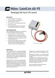
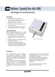
Main Parts<br />
Basics<br />
Basics<br />
Main Parts<br />
1.. 4-pole connector for computer<br />
connection.<br />
2.. Flashing green LED shows when<br />
activated<br />
3.. 6-pole connector for input signals.<br />
4.. Removable endpieces.<br />
5.. Aluminium casing<br />
10<br />
mitec<br />
mitec <strong>SatelLite</strong>
Basics<br />
Power Supply<br />
Power Supply<br />
<strong>SatelLite</strong> is designed and constructed for portable use.<br />
Internally it operates with a power supply of 5 V. The primary power<br />
supply unit is a common 1.5 V battery.<br />
It has a non-volatile memory and will retain its information even when<br />
the battery runs out.<br />
Battery replacement<br />
We recommend a 1.5V alcali battery of type IEC 6LR6. The battery is<br />
mounted to a holder inside the casing.<br />
• Remove both end pieces.<br />
• Extract the circuit card from the casing.<br />
• Install a new battery. NOTE! Turn the battery the correct<br />
way!<br />
• Put the circuit card in the lower end piece (the one with the<br />
4-pole connnector).<br />
• Pull the aluminium cover over the card and snap fasten it to<br />
the end piece.<br />
• Snap fasten the top end piece to the aluminium casing.<br />
The LED shall flash three times when the battery is snap fastened<br />
to the holder.<br />
A battery that is temporarily inserted incorrectly will not harm the<br />
instrument. However, after a while the protective circuit will burn off<br />
and this can cause serious permanent damage to the instrument.<br />
Therefore, always check that the battery is inserted the correct way.<br />
Power consumption<br />
In standby position <strong>SatelLite</strong> has a very low power consumption.<br />
During measuring the consumption will increase. The magnitude of the<br />
increase will depend on selected registration interval, measuring<br />
frequency and how often data is tapped from the memory. A normal life<br />
time for an alcali battery type LR6 is 1 month to 1 year.<br />
See further information below.<br />
Weak battery<br />
<strong>SatelLite</strong> continuously monitors the condition of the battery and will<br />
tell you in the program when it needs replacement.<br />
NOTE! Disconnect the cable to the PC when it isn’t in use. The power<br />
consumption from the battery in <strong>SatelLite</strong> increases when it is<br />
connected.<br />
mitec<br />
mitec <strong>SatelLite</strong> 11
Power Supply<br />
Basics<br />
Different types of batteries<br />
<strong>SatelLite</strong> only uses a so called 1.5V Pen Light battery (size AA, 14 x 50<br />
mm). This type of battery is both inexpensive and common and can be<br />
bought practically everywhere.<br />
We recommend an alcali battery type IEC LR6 as it has a high capacity.<br />
However, do note that even alcali batteries have different capacities.<br />
Some of the cheaper types have a capacity that is as low as approx.<br />
1800 mAh. Try to select a battery type that corresponds to the types<br />
indicated below.<br />
We recommmend:<br />
Duracell MN1500 with a specified capacity of 2700 mAh<br />
Varta 4006 with a specified capacity of 2500 mAh<br />
At low temperatures the capacity decreases and in these cases we<br />
recommend 1,5 V Lithium batteries for expample Energizer FR6.<br />
Common dry batteries type IEC R6 can also be used, but they do have a<br />
life time that is less than half of the alcali batteries. We do not<br />
recommend use of the brown stone batteries due to their short life time.<br />
You can also find NiCd batteries in this size, but again we do not<br />
recommend that you use them. One of the reasons is that they are a<br />
potential hazard to the environment and the other reasons are their poor<br />
capacity and relatively high cost.<br />
Calculation of battery life time<br />
The <strong>Mitec</strong> programs WinSat, WinLog and Monitor are used for the<br />
programming of <strong>SatelLite</strong>.<br />
During the programming you also state the capacity of the selected<br />
battery. If the battery is new you state the capacity as indicated on the<br />
battery. If the battery is used you must estimate the remaining capacity.<br />
The program will then calculate expected life time on the basis of how<br />
the instrument is setup and will indicate how many days it will last.<br />
This calculation is based on the assumption that the capacity will not<br />
fall due to e.g. low temperature.<br />
Do note that the stated capacity is valid at room temperature. The<br />
capacity drops at low temperatures. This is especially important to note<br />
with brown stone batteries as they are quite unsuitable for use in<br />
temperatures below zero.<br />
When the instrument is reprogrammed, the program will remember the<br />
consumed capacity in the battery and will take regard of that when a<br />
new calculation is made.<br />
However, if you remove the battery this information will be lost and<br />
you must yourself estimate how much of its capacity is left. The<br />
program will automatically discover that the battery has been removed<br />
and will alarm for this.<br />
If the battery runs out of power while measuring you will not lose the<br />
measured data, they can be read when a new battery has been installed.<br />
12<br />
mitec<br />
mitec <strong>SatelLite</strong>
Basics<br />
Sensor<br />
Sensor<br />
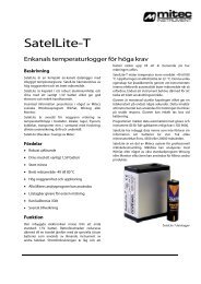
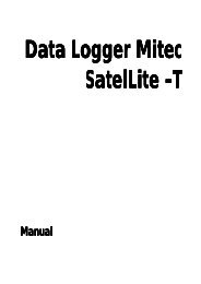
Signal cables<br />
Different signal cables are available as accessories:<br />
MS-UD101 0-1V DC.<br />
MS-UD102 0-10V DC.<br />
MS-ID100 0-20 (4-20) mA DC.<br />
MS-DP100 Pulse (max 4 Hz). Contact closure and 4-24V pulse.<br />
MS-UD101. 0-1V DC<br />
-<br />
+<br />
WHITE<br />
BLACK<br />
RED<br />
GREEN<br />
YELLOW<br />
BLUE<br />
Signal cable<br />
MS-UD102. 0-10V DC<br />
-<br />
WHITE<br />
BLACK<br />
RED<br />
GREEN<br />
YELLOW<br />
BLUE<br />
+<br />
Signal cable<br />
MS-ID101. 0-20 mA DC<br />
-<br />
+<br />
WHITE<br />
BLACK<br />
RED<br />
GREEN<br />
YELLOW<br />
BLUE<br />
50 ohm<br />
Signal cable<br />
MS-DP100. Pulse<br />
-<br />
WHITE<br />
BLACK<br />
RED<br />
GREEN<br />
YELLOW<br />
BLUE<br />
+<br />
Signal cable<br />
mitec<br />
mitec <strong>SatelLite</strong> 13
Start of the instrument<br />
Basics<br />
Automatic input adaptation<br />
The signal cables is connected via a 6-pole gold plated modular<br />
connector. <strong>SatelLite</strong> recognise the cable type by identifying the wiring<br />
(See above).<br />
When the cable is connected the instrument adapts itself automatically<br />
and use the appropriate scaling. Information (measuring range and sort)<br />
concerning the input, is stored with the measured data and transferred<br />
to PC for presentation.<br />
This unique feature makes <strong>SatelLite</strong>-U very flexible and the same<br />
instrument can be used for different measurements.<br />
<strong>SatelLite</strong>-U can be used for many different sensors and instruments<br />
with an output signal, for example pressure transmitters, water meters,<br />
CO2-meters, humidity sensors, and all industrial transmitters with an 0-<br />
20 (4-20) mA signal.<br />
The PC software WinLog and Monitor has built in functions for scaling<br />
and adaptation of diagrams, while the smallest program WinSat is fixed<br />
to the cable used for the application.<br />
Note! Do not connect PC and sensor at the same time. The inputs are<br />
not galvanicly isolated and measurement as well as data transfer may be<br />
disturbed. Also the instrument could be destroyed if the voltage<br />
between PC COM-port and signal input are to high.<br />
Unplug the sensor cable when the PC is connected.<br />
Start of the instrument<br />
The instrument is ready for use as soon as the battery has been<br />
connected. <strong>SatelLite</strong> has a very low power consumption in standby<br />
position and therefore has no power switch.<br />
Resetting to zero after a battery replacement<br />
As soon as supply power is connected <strong>SatelLite</strong> will automatically<br />
perform a resetting to zero. This is acknowledged by three flashes from<br />
the LED.<br />
The instrument is now ready for use but not before certain<br />
configuration has been carried out with help of the PC program.<br />
Please continue your reading under ”Handling” below.<br />
14<br />
mitec<br />
mitec <strong>SatelLite</strong>
Handling<br />
Setup and Readings<br />
Handling<br />
Setup and Readings<br />
Use the PC<br />
All setup and readings on <strong>SatelLite</strong> are made from the PC. <strong>Mitec</strong><br />
provides three different programs. Programs with version 1.51 or later<br />
has to be used.<br />
<strong>SatelLite</strong> is connected to PC via <strong>Mitec</strong> LPC-7 cable.<br />
Note! Do not connect PC and sensor at the same time. The inputs are<br />
not galvanicly isolated and measurement as well as data transfer may be<br />
disturbed. Also the instrument could be destroyed if the voltage<br />
between PC COM-port and signal input are to high.<br />
Complete series of PC programs<br />
WinSat is specially made for <strong>SatelLite</strong> and only includes the basic<br />
functions.<br />
WinLog is the standard <strong>Mitec</strong> program for communication, analysis<br />
and calculation and it can be used with all <strong>Mitec</strong> data loggers.<br />
<strong>Mitec</strong> Monitor is the most advanced program and includes XYdiagrams,<br />
macro functions, modem communication, etc.<br />
All programs are in the English language with <strong>manual</strong>s in English and<br />
support from <strong>Mitec</strong>.<br />
Below we show only the functions in the programs that concern<br />
<strong>SatelLite</strong> at setup and checking. We refer you to the <strong>manual</strong> for each<br />
program regarding analysis of the measured data.<br />
General information about program setup<br />
The programs use somewhat different methods for ”Setup” but the<br />
functions all look alike when you start them up. Below we introduce the<br />
common parts.<br />
See further on in this <strong>manual</strong> for information about the installation of<br />
the WinSat program.<br />
mitec<br />
mitec <strong>SatelLite</strong> 15
Setup and Readings<br />
Handling<br />
<strong>SatelLite</strong> Setup<br />
The first box that is shown provides two choices, Status and<br />
Programming.<br />
Status is used to show the configuration of the instrument and what<br />
will happen when Prog is used for instrument setup.<br />
Optional communication port can be used.<br />
Status, general<br />
When the ”STATUS” key is depressed you can see configuration and<br />
operation of the instrument.<br />
Also see chapter ”Checking of Activity”.<br />
Programming, general<br />
g<br />
If you instead of status select ”PROG” the box below will be shown.<br />
16<br />
mitec<br />
mitec <strong>SatelLite</strong>
Handling<br />
Setup and Readings<br />
Further functions can be reached if you depress the ”ADVANCED”<br />
key.<br />
You can now do the desired settings. See below for a closer description.<br />
mitec<br />
mitec <strong>SatelLite</strong> 17
Set Date & Time<br />
Handling<br />
Set Date & Time<br />
The clock is one of the more important parts of the data logger. The<br />
quarts crystal clock in <strong>SatelLite</strong> can show year, month, day, hour,<br />
minute and second.<br />
The clock is read and adjusted from the PC-program.<br />
<strong>SatelLite</strong> Setup<br />
All configurations are performed under this function. Every time a new<br />
configuration is done the clock is also set.<br />
The program reads the actual time in the PC and loads this<br />
information to <strong>SatelLite</strong>.<br />
Therefore, make sure that the clock in the PC shows the correct<br />
time!<br />
THE CLOCK<br />
The clock is controlled by a quarts crystal and its accuracy is similar to a common wrist watch, i.e. the variation in error<br />
can be between a few seconds up to approx. 1 minute per month.<br />
18<br />
mitec<br />
mitec <strong>SatelLite</strong>
Handling<br />
Setting of Registration Interval<br />
Setting of Registration Interval<br />
The registration interval (the storage interval) is the time taken between<br />
two storages of measured values in the logger memory.<br />
Setting of registration interval<br />
• Select <strong>SatelLite</strong> Setup<br />
• Depress the Prog key.<br />
The programming box (see above) is shown.<br />
Select registration interval from the scroll bar.<br />
Store the settings<br />
Store the settings by pressing PROGRAM or make additional settings<br />
in the ADVANCED menu. Choose number of measurements for a<br />
registration.<br />
What is a registration interval<br />
The principle for a data logger (measured value sampler) is that it<br />
automatically makes measurements and stores these in its memory for<br />
later reading.<br />
A basic function is the registration interval, the time lapse between two<br />
storages in the memory. (Compare with the speed of the paper on a line<br />
printer).<br />
The table below shows available registration intervals.<br />
Interval Interval Interval<br />
0.25 s 1min 1 h<br />
0.50 s 2 min 2 h<br />
1 s 5 min 4 h<br />
2 s 10 min 6 h<br />
5 s 15 min 8 h<br />
10 s 30 min 12 h<br />
15 s -- 24 h<br />
30 s -- --<br />
mitec<br />
mitec <strong>SatelLite</strong> 19
Setting of Registration Interval<br />
Handling<br />
How is a registration performed<br />
The registered value is the mean value from a number of measurements.<br />
The number of measurements performed can be selected when<br />
programming. The alternatives are those shown in the scroll bar in the<br />
programming box.<br />
What interval shall be chosen<br />
Mainly two factors determine what interval to choose.<br />
The process time constant i.e., the most important one is how fast the<br />
input signal varies. To get a reasonably representative picture of the<br />
variations in the input signal you must make sure of at least two<br />
storages per period. The period time is defined as the time lapse<br />
between e.g., two max values (or min values) in a varying signal.<br />
Available memory is also of great importance. For every measurement<br />
you must make an estimate of the time required to fill the memory.<br />
How data is stored in the memory<br />
<strong>SatelLite</strong> normally has sufficient space for approx. 5.000 measured<br />
values and can be extended to accommodate approx. 20.000 measured<br />
values.<br />
When the memory is full the oldest values can either be discarded and<br />
replaced by a new value (standard condition) or the measurement can<br />
be stopped. This is determined during the programming. See chapter<br />
”Automatic Stop of Measurement”.<br />
When is the memory full<br />
The influencing factor here (apart from the memory size), is the<br />
registration interval.<br />
NOTE! The available memory is not exactly 5000 values, it varies<br />
somewhat due to the configuration.<br />
The tables below show the time it takes to fill the memory. With memory size 20 000 the times stated below will be<br />
quadrupled.<br />
Interval<br />
Time to fill<br />
memory<br />
Interval<br />
Time to fill<br />
memory<br />
Interval<br />
Time to fill<br />
memory<br />
0.25 s 20 min 1min 3 days 1 h 199 days<br />
0.50 s 40 min 2 min 7 days 2 h 398 days<br />
1 s 80 min 5 min 17 days 4 h 796 days<br />
2 s 3 h 10 min 33 days 6 h 1194 days<br />
5 s 7 h 15 min 50 days 8 h 1592 days<br />
10 s 13 h 30 min 99 days 12 h 2386 days<br />
15 s 20 h -- -- 24 h 4773 days<br />
30 s 40 h -- -- -- --<br />
20<br />
mitec<br />
mitec <strong>SatelLite</strong>
Handling<br />
Selection of Measuring Frequency<br />
Selection of Measuring Frequency<br />
Select number of measurements per registration<br />
In <strong>SatelLite</strong> you can choose how many measurements<br />
that shall be performed for each registration. The value<br />
that is stored (registered) is the mean value of the<br />
measurements.<br />
• Select <strong>SatelLite</strong> Setup<br />
• Depress the PROG key.<br />
The programming box is shown (see above).<br />
Select the measuring interval from the scroll<br />
bar.<br />
Store the settings<br />
Store the settings by pressing PROGRAM or make<br />
additional settings in the ADVANCED menu. Select<br />
number of measurements for a registration.<br />
Note! When using pulse input the measuring frequency<br />
has no significance, only registration interval has to be<br />
selected.<br />
Measuring frequency states how often a measurement shall take place. A registration (storage of data in the memory)<br />
is the mean value from a number of measurements. The number can be chosen as required.<br />
The table below shows available alternatives.<br />
Interval Measurements<br />
/registration<br />
Interval Measurements<br />
/registration<br />
Interval Measurements<br />
/registration<br />
0.25 s 1 1min 1-240 1 h 8-125<br />
0.50 s 1-2 2 min 1-240 2 h 15-240<br />
1s 1-4 5 min 1-150 4 h 30-240<br />
2 s 1-8 10 min 2-150 6 h 30-240<br />
5 s 1-20 15 min 2-225 8 h 60-240<br />
10 s 1-40 30 min 4-225 12 h 90-240<br />
15 s 1-60 -- -- 24h 180-240<br />
30 s 1-120 -- -- -- --<br />
mitec<br />
mitec <strong>SatelLite</strong> 21
Manual Start and Stop<br />
Handling<br />
Manual Start and Stop<br />
The collection of measured values can start as soon as the setup<br />
described in the preceding chapter has been made. This can be done<br />
automatically or <strong>manual</strong>ly. Below we describe the procedure for a<br />
<strong>manual</strong> start/stop.<br />
Immediate start of the measurement<br />
The measurement can be started in conjunction with the programming<br />
of the instrument.<br />
• Select <strong>SatelLite</strong> Setup<br />
• Push the PROG key.<br />
The programming box (see above) is shown.<br />
• Push the ADVANCED key.<br />
The dialogue box extends. The extension includes a section<br />
about start conditions.<br />
Choose the alternative ”Immediate” to start the measurement in<br />
conjunction with the programming.<br />
Note! The signal cable has to be connected to the 6-pole connector<br />
before log starts.<br />
If no signal cable is connected to the 6-pole connector, the log start will be delayed until the connector is plugged in.<br />
This goes for all start conditions, both delayed and immediate.<br />
22<br />
mitec<br />
mitec <strong>SatelLite</strong>
Handling<br />
Manual Start and Stop<br />
Stop the measurement immediately<br />
The measurement continues until the next programming opportunity<br />
(unless you have selected automatic stop).<br />
The above dialogue box will show if you try to program a <strong>SatelLite</strong><br />
while a measurement is in progress.<br />
Push ”YES” to stop the measurement and ”NO” to continue with an<br />
uninterrupted logging.<br />
Start and stop can also be made at a specific time. See chapters ”Automatic Start of Measurement” and ”Automatic<br />
Stop of Measurement".<br />
NOTE. A reprogramming will automatically erase all previously collected information. This is the only time the memory<br />
will be emptied.<br />
mitec<br />
mitec <strong>SatelLite</strong> 23
Conditional Start and Stop of Logging<br />
Handling<br />
Conditional Start and Stop of Logging<br />
Apart from starting the measurement with <strong>SatelLite</strong> <strong>manual</strong>ly it is<br />
possible to start the measurement conditionally or at a specific time.<br />
The logging can stop when the memory is full or at a specific time.<br />
Start at a specific time<br />
• Select <strong>SatelLite</strong> Setup<br />
• Push the PROG key.<br />
The programming box (see above) will show.<br />
• Push the ADVANCED key.<br />
The dialogue box for programming is also provided with a<br />
box for start up condition.<br />
Select the alternative ”Time start” and enter date and time for start of<br />
the logging.<br />
Store the Setting and activate Start<br />
When the desired conditions have been set and the configuration is<br />
complete you push key PROGRAM in the dialogue box.<br />
Note! When autostart has been activated the text "Begin" will show at<br />
status check until the startup conditions have been fulfilled and<br />
registration can start.<br />
Thereafter the text ”Running” will show.<br />
Start at a specific time can be very useful when trouble shooting. Time start is also used when you want to<br />
synchronise several different measuring instruments and this way get measured values taken at the same time.<br />
The measuring will proceed continuously after start until a stop condition has been fulfilled or you perform a <strong>manual</strong><br />
stop.<br />
NOTE! When start has been ordered and until the start conditions have been<br />
reached, the text Begin will be shown under Status check.<br />
This means that measurement has commenced but that the start conditions have<br />
not yet been met. As soon as the start conditions have been reached the text<br />
Running will be shown in the display and storing in the memory starts.<br />
The registration will continue until an automatic or <strong>manual</strong> stop has been ordered.<br />
24<br />
mitec<br />
mitec <strong>SatelLite</strong>
Handling<br />
Conditional Start and Stop of Logging<br />
Stop at a specific time<br />
• Select <strong>SatelLite</strong> Setup<br />
• Push the PROG key.<br />
The programming box (see above) will be shown.<br />
• Push the ADVANCED key.<br />
The dialogue box for programming includes a box for stop<br />
conditions.<br />
Select the alternative ”Time Stop”, enter date and time when you want<br />
the logging to stop.<br />
Stop when memory is full<br />
The box for stop conditions also includes the alternative<br />
”Memory Full”.<br />
Store the Settings and activate start<br />
When the desired conditions have been selected and the configuration<br />
is completed you store the settings by pushing the PROGRAM key in<br />
the dialogue box.<br />
mitec<br />
mitec <strong>SatelLite</strong> 25
Checking of Activity<br />
Handling<br />
Checking of Activity<br />
LED on <strong>SatelLite</strong><br />
A green LED sits behind the computer contact. When the instrument is<br />
logging normally it flashes every four second. When zeroing it flashes<br />
every third second.<br />
How does the instrument operate<br />
For fast information about the procedure and how the instrument<br />
operates the <strong>Mitec</strong> programs have the function STATUS. This function<br />
you find under menu ”<strong>SatelLite</strong> Setup”.<br />
<strong>SatelLite</strong> Setup<br />
The first box shown offers two alternatives Status and Programming.<br />
Status is used to show the instrument settings and what happens.<br />
Optional communication port can be used.<br />
Prog is described in another place.<br />
Status<br />
When you push the”Status”key the information stored in <strong>SatelLite</strong> will<br />
be entered and displayed. The first box shown is the summary box<br />
shown below.<br />
By pushing key ”ADVANCED” you obtain further information:<br />
26<br />
mitec<br />
mitec <strong>SatelLite</strong>
Handling<br />
Checking of Activity<br />
Status ”Information”<br />
Logger: Shows type of instrument and its serial number. Each instrument has its own individual serial number given<br />
during the manufacturing.<br />
Logging: Shows current activity. This can be Stop, Begin or Running. Se below for explanation.<br />
Signal type: Shows the type of input signal to the logger.<br />
Number of registrations: Apart from the number it also displays the total memory space available. Note 1.<br />
Remaining in battery: Consumed capacity is calculated. Note 2.<br />
Current time: Shows the time in the logger when the status key was pushed (+3 seconds).<br />
Status ”Programming”<br />
Executed: Date and time of the programming.<br />
Start condition: Set start condition.<br />
Stop condition: Set stop condition<br />
Interval: The registration interval. Within brackets it displays the time lapse between the measurements (the<br />
measuring interval).<br />
Status ”Logger”<br />
Version: The instrument version number.<br />
Manufacturing date: The date when the instrument software was loaded.<br />
Status ”Battery”<br />
Stated battery capacity: The capacity figure entered by the operator at battery replacement. Note 3.<br />
Time elapsed since last battery replacement: Time elapsed since the latest power interruption and new statement<br />
regarding the battery capacity. (In practise the time elapsed since the battery was inserted).<br />
Operation time since the battery was replaced: Time the instrument has been used for logging, i.e. active operation<br />
time. Note 4.<br />
Status ”Logging”<br />
Oldest: Time for the oldest registration stored in the memory at the status request.<br />
Latest: Time for the youngest (latest) registration stored in the memory at the status request.<br />
The table below explains the status information in box ”Information / Logging”.<br />
mitec<br />
mitec <strong>SatelLite</strong> 27
Checking of Activity<br />
Handling<br />
STOP<br />
No registration is active. The memory<br />
contains information collected during the<br />
previous measuring period. (Or is empty if no<br />
measurement has been done since the<br />
zeroing.<br />
RUNNING<br />
Means that the start condition has been met<br />
and measurement is in progress. This is the<br />
normal condition at logging.<br />
BEGIN<br />
This means that you have chosen to start on<br />
an external condition. Measurement has<br />
been ordered but the start condition has not<br />
yet been met.<br />
Note 1<br />
Memory consumption. Note, the memory is full if the figures for number of registrations and available memory are<br />
equally large. Logging can still be in progress depending on the stop condition you have chosen.<br />
Note 2.<br />
Remaining in battery. This calculation is based on the capacity stated by the operator during programming. NOTE!<br />
The calculation is based on a typical power consumption and is not exact. <strong>SatelLite</strong> will remember how much has been<br />
consumed of the installed battery and will disregard a new statement for battery capacity. To change the capacity you<br />
must remove the battery and reinstall it.<br />
Note 3.<br />
Battery capacity. <strong>SatelLite</strong> will notice it the power has been disconnected and will give alarm for this at the next<br />
programming. The operator shall then enter a figure for the capacity of the battery that has just been installed. The<br />
capacity shall be entered in conjunction with the installation of the battery. This figure will be used by <strong>SatelLite</strong> until the<br />
battery is removed and installed again.<br />
Read about power supply in chapter ”BASICS”.<br />
Note 4.<br />
Operation time. This time is the sum of the time that the instrument has been used for logging, i.e. the time for<br />
measuring. Standby with stopped logging is not counted. The operation time counter will be zeroed when the battery is<br />
replaced (when a new capacity is entered).<br />
28<br />
mitec<br />
mitec <strong>SatelLite</strong>
Handling<br />
Download data to PC<br />
Download data to PC<br />
Information from <strong>SatelLite</strong> can simply be downloaded to PC for further<br />
calculations.<br />
The transmission is made by a serial communication via RS232.<br />
Normally you need make no settings on <strong>SatelLite</strong> and the transmission<br />
is started and controlled completely from the PC.<br />
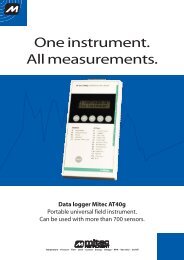
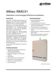
Connect the computer<br />
The connection to the computer is done with a cable provided with<br />
suitable contact devices.<br />
As an accessory to IBM PC and compatible units we carry cable LPC-7<br />
in stock. This can be used both for 25 and 9-pole contact devices in a<br />
PC.<br />
Connect the cable to the 4-pole modular contact on <strong>SatelLite</strong> and to a<br />
free COM: port on the PC.<br />
NOTE! Do check that no other program, e.g. the mouse, uses that<br />
COM port on the PC!<br />
TXD ----------------------------------------- 3 RXD<br />
RXD ----------------------------------------- 2 TXD<br />
CTS ----------------------------------------- 20 DTR<br />
Gnd ----------------------------------------- 7 Gnd<br />
<strong>SatelLite</strong><br />
contact<br />
Cable LPC-7<br />
PC 25-pole<br />
contact<br />
At startup of <strong>SatelLite</strong> you get a standard setting of the serial inport,<br />
which is 9600 baud, 8 bits, 1 stop-bit, no parity. WinSat and WinLog<br />
will automatically adjust to this.<br />
Readout of measured data<br />
Readout of the measured data differs somewhat between the programs.<br />
<strong>SatelLite</strong> shall be handled in the same manner as other products from<br />
<strong>Mitec</strong> in the handling of the readout.<br />
Data is stored in the same manner and measured data from <strong>SatelLite</strong><br />
can at the presentation and calculation be mixed with data from e.g.<br />
AT40 or other loggers.<br />
See the <strong>manual</strong> for each program!<br />
TRANSMISSION SPEED<br />
The speed of the data transmission is in baud and this can be translated as bits/second. One character is made up of<br />
10 bit. With a speed of 9600 baud you can transfer 960 characters per second and in <strong>SatelLite</strong> this means 500-700<br />
measured values per second. In practice the speed is lower due to control characters, etc.<br />
mitec<br />
mitec <strong>SatelLite</strong> 29
Series and Revision number<br />
Handling<br />
Program in PC<br />
A program that can communicate with binary numbers is required to<br />
receive information from <strong>SatelLite</strong>.<br />
The program WinSat is an accessory to <strong>SatelLite</strong>. This program can be<br />
used to transmit data to a PC for a simple presentation or for<br />
transmission to a calculation program type Excel or Lotus 1-2-3.<br />
<strong>Mitec</strong> can also provide complete communication and analysis programs<br />
for Windows. <strong>Mitec</strong> WinLog is a powerful program for<br />
communication, storage of data, calculation and presentation.<br />
<strong>Mitec</strong> Monitor is an extended version of WinLog and this program<br />
includes automatic communication via modem.<br />
Programs with version 1.51 or later has to be used.<br />
WinSat as well as Monitor and WinLog require Windows 3.1 and at<br />
least a 386-PC with 4 Mbit RAM.<br />
Series and Revision number<br />
The Status function can provide information about instrument type and<br />
serial number.<br />
You will also find a space for the instrument number on the label stuck<br />
to the instrument end piece. Check the series number with the ”Status”<br />
function in the program and write down this number on the label using<br />
a ball-point pen.<br />
30<br />
mitec<br />
mitec <strong>SatelLite</strong>
Handling<br />
WinSat introduction<br />
WinSat introduction<br />
General information about WinSat<br />
WinSat is a program in the same series as <strong>Mitec</strong> Monitor and WinLog.<br />
WinSat can only be used with the <strong>Mitec</strong> <strong>SatelLite</strong> series, while the<br />
other programs also can be used together with other <strong>Mitec</strong> instruments.<br />
How to Install<br />
Insert the diskette in A:<br />
• Select ”Run” in the program manager ”File” menu.<br />
• Write A:\install<br />
The program will now be automatically installed. Answer<br />
to the questions as needed. Program group <strong>Mitec</strong> WinSat<br />
will be created.<br />
Start the program<br />
Double click on the <strong>SatelLite</strong> icon. This will start the program and<br />
display the welcome page.<br />
The top part of the menu looks as the picture below.<br />
Program function<br />
The program is very simple to use and has been made so it is<br />
”selfinstructing”. The handling of WinSat is only described in the<br />
program help text. You find this text under ”?” on the menu.<br />
Quick start<br />
Click ”File” and select ”Setup”. Here you do all the configurations<br />
needed to start up <strong>SatelLite</strong>. See previous sections in this <strong>manual</strong>.<br />
Collect the measured data under ”File” and ”Collect Data”.<br />
Diagrams will be created automatically as soon as the sampling is<br />
completed.<br />
mitec<br />
mitec <strong>SatelLite</strong> 31
WinSat introduction<br />
Handling<br />
Structure<br />
The measurement is performed on an Object. Enter the name of the<br />
object when starting the sampling.<br />
You will find the measured data under the object name when you select<br />
”Open” and a diagram will be displayed.<br />
In WinSat a measurement and a diagram is the same thing. Do note that<br />
you can ”add” data to an already existing object.<br />
The measured data will be stored in the same format as in the other<br />
programs from <strong>Mitec</strong>, Monitor and WinLog, and can be transferred to<br />
these programs.<br />
Analysis<br />
Measured data displayed in the diagram can be studied using the<br />
different tools.<br />
Put the cursor in the diagram and click the right mouse key. Test!<br />
Also test the zooming function by using the flexible axis’s. Point to a<br />
value on the time or Y-axis and drag the value to a new position.<br />
Ready!<br />
The menu has scrolling arrows and zoom keys .<br />
And a key that restores everything.<br />
Use the keys below to print out the diagram or to export it to the editing<br />
board. .<br />
No calculations can be made in WinSat. Instead use WinLog or<br />
Monitor that both are equipped with an advanced and easy to use<br />
formula language.<br />
Test all the program functions and search through the help text.<br />
.<br />
32<br />
mitec<br />
mitec <strong>SatelLite</strong>
Additional Information<br />
What is a Data logger?<br />
Additional Information<br />
What is a Data logger?<br />
Background<br />
The term data logger we have, as with many<br />
other technical terms, borrowed from the English<br />
language. Log comes from the naval term to log<br />
meaning in a logbook, i.e. to make careful notes<br />
about events.<br />
With data logger we then mean careful ”notes” of<br />
measured data in a mass memory.<br />
We prefer the term measured value collector, but<br />
it is of course more international to use the term<br />
data logger.<br />
<strong>Mitec</strong> introduced its first data logger on the<br />
market in 1984. It was the 4-channel logger<br />
MTM20 that we called a TEMP-recorder.<br />
Shortly afterwards we introduced its sister<br />
instrument, the PULSE-recorder PM20. The next<br />
generation was the ANALOG-recorder AT30<br />
and now we have come to the third generation,<br />
the UNIVERSAL-recorders <strong>SatelLite</strong> and AT31.<br />
Our product names have made their mark. In<br />
Sweden you can e.g. look in the " Buyers Guide<br />
for Engineers " (Ekonomisk Litteratur <strong>AB</strong>) under<br />
"Recorder" where out product names have been<br />
used as headlines in the product index. We can<br />
only say Thank You! for that.<br />
The data logger is not a new invention. You can<br />
find old literature references, such as e.g.<br />
"Airborne recorder and Computer Speed flighttest<br />
Data Processing System" from 1958.<br />
The loggers were developed in step with the<br />
development of the semi-conductors. The<br />
microprocessor plays a very important role here.<br />
The real and major break-through came in the<br />
beginning of the 90’s after the logger had gained<br />
its general acceptance.<br />
How does it work?<br />
The principle is rather simple. The main parts of<br />
a modern logger are the microprocessor, the<br />
semi-conductor memory and an analogue/digital<br />
converter.<br />
A sensor gives an analogue signal, e.g. 4-20mA.<br />
The micro processor that has a built-in clock<br />
controls the process. The sensor is read at set<br />
time intervals and the measured values are stored<br />
in the memory.<br />
Eventually it has collected a number of measured<br />
values that form a time series. The time series<br />
can be printed out as a diagram on a printer or on<br />
a computer screen<br />
Modern data loggers are rather sophisticated and<br />
offer different possibilities on how to treat the<br />
information. Below we have described some of<br />
the more common terms.<br />
Memory is of course quite important. Common<br />
sizes are for approx.1000 values up to several<br />
100 000. There are non-volatile memories<br />
available with a built-in battery so they will not<br />
lose data in case of a power failure.<br />
Measuring channels will tell you how many<br />
sensors that can be connected at the same time.<br />
Handheld professional loggers generally have 2<br />
to 8 channels.<br />
Type of input tells you about the type of sensor<br />
that can be connected. Most sensors can measure<br />
temperature or a voltage signal e.g. 0-10V.<br />
Different types of sensors can be connected to<br />
the more advanced loggers.<br />
Registration interval is the time between two<br />
storages in the memory. It is usually adjustable in<br />
steps between 1 s and 24 hours. The registration<br />
interval determines how fast processes you can<br />
measure on. A rule of thumb is to make at least<br />
two registrations per period for the measuring<br />
signal.<br />
Measuring interval is the time between two<br />
measurements. The most modern loggers<br />
measure several times per registration to make<br />
sure of a more accurate value. The measuring<br />
interval can be adjustable.<br />
A clock is required. A modern logger has a<br />
calendar clock (crystal clock) with date and<br />
time.<br />
Start condition is the condition that must be met<br />
before measurement can start and data be stored<br />
in the memory. It can be <strong>manual</strong> start, time start<br />
mitec<br />
mitec <strong>SatelLite</strong> 33
What is a Data logger?<br />
Additional Information<br />
or start on external condition, (e.g. when a<br />
temperature is exceeded).<br />
Stop condition determines when the<br />
measurement shall stop. It can be <strong>manual</strong>, on<br />
time, or when the memory is full.<br />
Storing conditions can be set on some loggers. It<br />
is e.g. possible to store only the mean value<br />
during a registration or several values. e.g. min,<br />
mean and max.<br />
How to take care of the measured data<br />
The collected measured values are stored in<br />
digital form as data words. Before you can use<br />
the information it must be treated.<br />
Older loggers only printed out the information as<br />
numeric values on a printer. This resulted in long<br />
and cumbersome tables that were hard to<br />
interprete.<br />
The best way is to present the information in the<br />
shape of a curve. Some loggers can draw curves<br />
directly on a printer or a plotter, and this is<br />
acceptable if you are satisfied with unprocessed<br />
data.<br />
The most common method is to transmit the<br />
information to a PC for analysis in a program.<br />
The main advantages with this are that the<br />
information then can be stored on a magnet<br />
media for later analysis and that the work<br />
involved with the analysis has been made easier<br />
as the calculation and presentation capacity of<br />
the computer can be used.<br />
Modern personal computers using Windows have<br />
made possible a very efficient handling due to<br />
the graphical interface using the mouse as a<br />
pointer.<br />
What must be considered.<br />
One of the first items is to make sure that you<br />
have an instrument that is up to the present work<br />
situation, in other words it must be ”good<br />
enough”.<br />
Type.<br />
You must first decide if the instrument shall be<br />
portable or have a fixed installation. For field<br />
measurements the requirements are low weight<br />
and battery operation.<br />
Some suppliers use the PC also in the field.<br />
Don’t forget that the PC is attractive to thieves,<br />
never leave it unguarded!<br />
Some of the cheaper loggers are made as ”black<br />
boxes” without keys and display. These leave<br />
you completely dependent on the PC for<br />
configurations and control of the operation, even<br />
in the field. These loggers often have a fixed<br />
built-in battery and the instrument will be<br />
dumped when the battery runs out.<br />
Ergonomics<br />
Unfortunately this area has been very "hightech"-inspired.<br />
Many instruments are difficult to<br />
overview and have a number of keys for different<br />
functions. Select an instrument that has a logical<br />
construction. It should also have a display with<br />
letters and figures and some clearly marked keys.<br />
Extension.<br />
Also check the procedure for connection of<br />
sensors of different types and to extend the<br />
equipment. Some instruments are only<br />
constructed for certain types of sensors. If you<br />
want to connect other sensors you then either<br />
have to purchase a new instrument or special<br />
circuit cards.<br />
Battery life time.<br />
It is important to check the power consumption.<br />
A modern battery driven logger should not in<br />
stand-by position consume more than 0.1 mA.<br />
When measuring it may consume a lot more,<br />
approx. 30-40 mA. Do note that short registration<br />
intervals (1-30 secs.) increases the consumption<br />
sharply.<br />
Input signal.<br />
You get maximum flexibility if you select an<br />
instrument with universal inputs. To these you<br />
can, with a suitable cable and connection,<br />
directly connect different types of sensors.<br />
Some loggers require external signal transducers<br />
to adjust the sensors. Consider that these<br />
generally use a lot of power and that they also<br />
take up space.<br />
A very important aspect is the power supply to<br />
the sensors. If you have to arrange for an external<br />
supply it will mean a hazzle with extra cables.<br />
34<br />
mitec<br />
mitec <strong>SatelLite</strong>
Additional Information<br />
What is a Data logger?<br />
Quality loggers have a built-in supply directly via<br />
the sensor cable.<br />
Watch out for the power consumption here! E.g.<br />
a humidity sensor can exhaust a 9 V battery in 24<br />
hours if connected the whole time. Select a<br />
logger that can control the power supply to the<br />
sensor.<br />
customer you are always close to the source. You<br />
can get help and advice if you have a<br />
measurement problem.<br />
We deliver instruments for physical measuring<br />
signals, i.e. we don’t leave you with a 0-10 V<br />
input. We also deliver the sensor or a cable that<br />
directly fits the sensor you already have.<br />
Accuracy.<br />
Many suppliers make no difference between<br />
resolution and accuracy and yet they are two<br />
different things. The resolution indicates how<br />
”small” the parts of the signal are that can be<br />
spotted. Many suppliers have for reason of cost<br />
only used 8 bits and this can give a resolution of<br />
1/256. With a measuring range of e.g. 300°C /<br />
572°F this means a resolution of just over 1°C /<br />
1.8°F. You should ask for at least 10-12 bits (a<br />
resolution of 1/1000 to 1/4000).<br />
Accuracy is an indication of how well everything<br />
works together. This should be specified in a<br />
technical unit, e.g. °C or in %. You should also<br />
require that the supplier can show a traceability<br />
for the calibration, i.e. that he can show that the<br />
instrument measures correctly.<br />
Memory.<br />
These days the memory capacity is no limitation.<br />
25-50 000 measured values is standard. Do note!<br />
Some suppliers show the memory in kbyte<br />
(kilobyte = 1000 byte). To store a measured<br />
value with an acceptable resolution you need 2<br />
byte i.e. 128 kbyte is sufficient for 64000<br />
measured values. Most memories can also be<br />
delivered with a power failure protection.<br />
Manuals.<br />
Make sure you get <strong>manual</strong>s in your own<br />
language. Check that the supplier can give<br />
service!<br />
<strong>Mitec</strong> data loggers.<br />
The <strong>Mitec</strong> data loggers are designed and<br />
manufactured by <strong>Mitec</strong> in Säffle, Sweden. As a<br />
Field adjusted.<br />
Our instruments are made for the user. We put<br />
great emphasis on simple handling and on<br />
flexibility. <strong>SatelLite</strong>, our latest logger is based on<br />
our 10 year long manufacturing experience of<br />
data loggers for use in the field<br />
Simple handling.<br />
A display in English will tell you exactly how to<br />
make the configuration. The simple and clear<br />
structure of settings and readings ensures that<br />
you learn to master the instrument in your first<br />
tryout.<br />
Flexible.<br />
Universal inputs for volt, mA, electricity meters,<br />
temperature sensors, current clamps, flowmeters,<br />
etc. ensure that our instruments can be used for a<br />
great number of applications. Without<br />
reconstruction or additions. Our concept with<br />
”smart cables” see to it that you directly can se<br />
signal type and unit in the display without any<br />
programming.<br />
Technical performance.<br />
State-of-the art technology of the<br />
microprocessors provide us all with the<br />
possibility to build "high-tech-Christmas trees".<br />
However, our long experience has taught us that<br />
technology is not an end in itself. Our<br />
instruments have a ”sufficient” capacity, to quote<br />
a known English car manufacturer.<br />
You still do not believe us? Ask a colleague who<br />
already has a <strong>Mitec</strong> instrument.<br />
mitec<br />
mitec <strong>SatelLite</strong> 35
Technical specifications<br />
Additional Information<br />
Technical specifications<br />
GENERAL<br />
Number of measuring channels 1<br />
Memory size<br />
8k or 32k byte. 8k memory is standard, the others are options<br />
Resolution storage<br />
12 bits<br />
Number of measured values 4,500 or 20,000.<br />
Clock<br />
Crystal controlled, date and time.<br />
Registration interval On time: 0.25, 0.5, 1.2, 5, 10, 15 or 30 sec. 1, 2, 5, 10, 15 or 30 min. 1, 2, 4, 6,<br />
8, 12, or 24 hours<br />
Measuring frequency<br />
Optional for each registration interval<br />
Power Supply<br />
1.5 V battery LR6 (alkali) or Lithium size AA<br />
Battery life span<br />
1 month up to 1 year. (Depending on registration interval, measuring time and<br />
ambient temperature)<br />
Ambient temperature<br />
-20 °C to +50 °C / -4° to +122°F. No condense.<br />
EU standard<br />
EN50081-1, EN50081-2, EN50082-1<br />
INPUTS<br />
Types<br />
Voltage DC, Current DC, pulses<br />
Input selection<br />
Automatic detection.<br />
Linearising<br />
Automatic<br />
Measuring ranges analogue inputs 0-1V DC, 0-10V DC, 0-20 / 4-20 mA DC<br />
Inaccuracy 0-1V range ±0.4%, range 4-20mA and 0-10V ±0.6%<br />
Input type pulse<br />
potentialfree contact, open collector or voltage 4-24V DC<br />
Measuring range pulses<br />
0-4 Hz<br />
Minimum pulse length<br />
30 ms<br />
FUNCTIONS<br />
Start and stop conditions<br />
Adjustable, time and <strong>manual</strong> start. Time, <strong>manual</strong> and memory full stop<br />
Storage method<br />
Mean value, adjustable number of measurements per registration.<br />
Reading and setting<br />
Via PC and one of the <strong>Mitec</strong> programs WinSat, WinLog or Monitor.<br />
COMMUNICATION<br />
Computer<br />
RS232, 9600 baud. Control signal from the computer.<br />
Indication<br />
LED. One flash every 4:th second while logging is in progress.<br />
MECHANICS<br />
Contact device 4 pole modular contact, 4/4 and 6 pole modular contact, 6/6<br />
Box<br />
Aluminium 60 x 50 x 30 mm / 2.36 x 2 x 1.2 in.<br />
Weight<br />
80 g / 0.18 lbs including battery.<br />
We reserve the right to make technical improvements without prior notice.<br />
Connectors<br />
Modular connectors<br />
The 4-pin contact is used for communication with external units.<br />
<strong>Mitec</strong> cables LPC-7 are used for connection to PC. See the chapter<br />
above.<br />
The 6-pin connector is used for connecting input signals. An signal<br />
cable wired as described in chapter above has to be used.<br />
36<br />
mitec<br />
mitec <strong>SatelLite</strong>
Additional Information<br />
CE-marking<br />
Declaration of conformity<br />
Manufacturer:<br />
Equipment type number:<br />
Description of Equipment:<br />
European standards:<br />
<strong>Mitec</strong> <strong>Instrument</strong> <strong>AB</strong><br />
Västra Storgatan 18, P.O.Box 91,<br />
S-66122 Säffle, Sweden<br />
<strong>SatelLite</strong><br />
Portable Data Logger<br />
EN50081-1, EN50081-2, EN50082-1<br />
We certify that the apparatus identified above conforms with the requirements of Council Directive<br />
89/336/EEC as amended by Directives 91/263/EEC and 92/31/EEC.<br />
September 9 1996<br />
<strong>Mitec</strong> <strong>Instrument</strong> <strong>AB</strong><br />
Bertil Olsson<br />
Managing Director<br />
mitec<br />
mitec <strong>SatelLite</strong> 37
Service and Support<br />
Additional Information<br />
Service and Support<br />
Telephone support<br />
The <strong>Mitec</strong> products are constructed and manufactured by <strong>Mitec</strong><br />
<strong>Instrument</strong> <strong>AB</strong> in Säffle, Sweden.<br />
We offer full service of the equipment in our work shop. In case of a<br />
problem, please contact us on our telephone number +46 533 16050.<br />
Fax & E-mail<br />
E<br />
Our fax number is + 46 533 16045.<br />
Our E-mail address is info@mitec.se.<br />
Homepage<br />
You find our homepage on: http://www.mitec.se<br />
There you find Demo-versions of our programs, a listing of the latest<br />
probes and a variety of help-programs.<br />
Goods<br />
Equipment sent in for service and calibration should be sent to:<br />
<strong>Mitec</strong> <strong>Instrument</strong> <strong>AB</strong><br />
Västra Storgatan 18<br />
S-661 30 Säffle, Sweden<br />
Always include an accompanying note and a simple description of what<br />
you want done.<br />
38<br />
mitec<br />
mitec <strong>SatelLite</strong>
Additional Information<br />
Index<br />
Index<br />
A<br />
Additional information, 33<br />
Adress, 38<br />
B<br />
Basics, 10<br />
Battery<br />
Capacity, 12; 28<br />
C<br />
Cables<br />
To PC, 29<br />
To sensors, 13<br />
CE-mark, 37<br />
Checking of activity, 26<br />
Clock, 18<br />
Connect<br />
Battery, 10<br />
PC, 10; 29<br />
Connectors, 10; 36<br />
Contents, 5<br />
D<br />
Date and time, 18<br />
E<br />
Excel, 30<br />
G<br />
General description, 7<br />
H<br />
Handling, 15<br />
L<br />
LED, 26<br />
Lotus 1-2-3, 30<br />
M<br />
Measuring Frequency, 21<br />
Memory size, 20<br />
Monitor, 30<br />
P<br />
PC, 29<br />
Power Sypply, 11<br />
Program in PC<br />
Excel, 30<br />
Lotus 1-2-3, 30<br />
MCOM, 30<br />
<strong>Mitec</strong> Monitor, 30<br />
<strong>Mitec</strong> WinLog, 30<br />
R<br />
Registration Interval, 19<br />
S<br />
Sensor, 10<br />
Serial number, 30<br />
Service, 38<br />
Setup, 15; 16<br />
Measuring Frequency, 21<br />
Registration Interval, 19<br />
Start and stop, 22<br />
Stop when memory full, 25<br />
Time start, 24<br />
Time stop, 25<br />
Start, 14<br />
Start on external condition, 24<br />
Status, 26<br />
Stop on external condition, 25<br />
Stop when memory is full, 25<br />
Support, 38<br />
E-mail, 38<br />
Fax, 38<br />
T<br />
Technical specifikation, 36<br />
Time, 18<br />
W<br />
Weak Battery, 11<br />
WinLog, 30<br />
WinSat, 31<br />
mitec<br />
mitec <strong>SatelLite</strong> 39