

ama_Ch17
ama_Ch17
ama_Ch17

You also want an ePaper? Increase the reach of your titles
YUMPU automatically turns print PDFs into web optimized ePapers that Google loves.
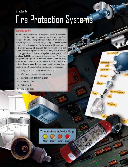
Chapter 17<br />
Fire Protection Systems<br />
Introduction<br />
Because fire is one of the most dangerous threats to an aircraft,<br />
the potential fire zones of modern multiengine aircraft are<br />
protected by a fixed fire protection system. A fire zone is an<br />
area, or region, of an aircraft designed by the manufacturer<br />
to require fire detection and/or fire extinguishing equipment<br />
and a high degree of inherent fire resistance. The term<br />
“fixed” describes a permanently installed system in contrast<br />
to any type of portable fire extinguishing equipment, such<br />
as a hand-held Halon or water fire extinguisher. A complete<br />
fire protection system on modern aircraft, and on many<br />
older aircraft, includes a fire detection system and a fire<br />
extinguishing system. Typical zones on aircraft that have a<br />
fixed fire detection and/or fire extinguisher system are:<br />
1. Engines and auxiliary power unit (APU)<br />
2. Cargo and baggage compartments<br />
3. Lavatories on transport aircraft<br />
4. Electronic bays<br />
5. Wheel wells<br />
6. Bleed air ducts<br />
17-1
To detect fires or overheat conditions, detectors are placed<br />
in the various zones to be monitored. Fires are detected in<br />
reciprocating engine and small turboprop aircraft using one<br />
or more of the following:<br />
1. Overheat detectors<br />
2. Rate-of-temperature-rise detectors<br />
3. Flame detectors<br />
4. Observation by crewmembers<br />
In addition to these methods, other types of detectors are<br />
used in aircraft fire protection systems but are seldom used<br />
to detect engine fires. For example, smoke detectors are<br />
better suited to monitor areas where materials burn slowly<br />
or smolder, such as cargo and baggage compartments.<br />
Other types of detectors in this category include carbon<br />
monoxide detectors and chemical sampling equipment<br />
capable of detecting combustible mixtures that can lead to<br />
accumulations of explosive gases.<br />
The complete aircraft fire protection systems of most large<br />
turbine-engine aircraft incorporate several of these different<br />
detection methods.<br />
1. Rate-of-temperature-rise detectors<br />
2. Radiation sensing detectors<br />
3. Smoke detectors<br />
4. Overheat detectors<br />
5. Carbon monoxide detectors<br />
6. Combustible mixture detectors<br />
7. Optical detectors<br />
8. Observation of crew or passengers<br />
The types of detectors most commonly used for fast detection<br />
of fires are the rate-of-rise, optical sensor, pneumatic loop,<br />
and electric resistance systems.<br />
Classes of Fires<br />
The following classes of fires that are likely to occur onboard<br />
aircraft, as defined in the U.S. National Fire Protection<br />
Association (NFPA) Standard 10, Standard for Portable Fire<br />
Extinguishers, 2007 Edition, are:<br />
1. Class A—fires involving ordinary combustible<br />
materials, such as wood, cloth, paper, rubber, and<br />
plastics.<br />
2. Class B—fires involving flammable liquids, petroleum<br />
oils, greases, tars, oil-based paints, lacquers, solvents,<br />
alcohols, and flammable gases.<br />
3. Class C—fires involving energized electrical<br />
equipment in which the use of an extinguishing media<br />
that is electrically nonconductive is important.<br />
4. Class D—fires involving combustible metals, such<br />
as magnesium, titanium, zirconium, sodium, lithium,<br />
and potassium.<br />
Requirements for Overheat and Fire Protection<br />
Systems<br />
Fire protection systems on current-production aircraft do not<br />
rely on observation by crew members as a primary method<br />
of fire detection. An ideal fire detector system includes as<br />
many of the following features as possible:<br />
1. No false warnings under any flight or ground<br />
condition.<br />
2. Rapid indication of a fire and accurate location of the<br />
fire.<br />
3. Accurate indication that a fire is out.<br />
4. Indication that a fire has re-ignited.<br />
5. Continuous indication for duration of a fire.<br />
6. Means for electrically testing the detector system from<br />
the aircraft cockpit.<br />
7. Resists d<strong>ama</strong>ge from exposure to oil, water, vibration,<br />
extreme temperatures, or handling.<br />
8. Light in weight and easily adaptable to any mounting<br />
position.<br />
9. Circuitry that operates directly from the aircraft power<br />
system without inverters.<br />
10. Minimum electrical current requirements when not<br />
indicating a fire.<br />
11. Cockpit light that illuminates, indicating the location<br />
of the fire, and with an audible alarm system.<br />
12. A separate detector system for each engine.<br />
Fire Detection/Overheat Systems<br />
A fire detection system should signal the presence of a fire.<br />
Units of the system are installed in locations where there are<br />
greater possibilities of a fire. Three detector system types in<br />
common use are the thermal switch, thermocouple, and the<br />
continuous loop.<br />
Thermal Switch System<br />
A number of detectors, or sensing devices, are available.<br />
Many older-model aircraft still operating have some type of<br />
thermal switch system or thermocouple system. A thermal<br />
switch system has one or more lights energized by the aircraft<br />
17-2
power system and thermal switches that control operation of<br />
the light(s). These thermal switches are heat-sensitive units<br />
that complete electrical circuits at a certain temperature. They<br />
are connected in parallel with each other but in series with<br />
the indicator lights. [Figure 17-1] If the temperature rises<br />
above a set value in any one section of the circuit, the thermal<br />
switch closes, completing the light circuit to indicate a fire<br />
or overheat condition. No set number of thermal switches<br />
is required; the exact number is usually determined by the<br />
aircraft manufacturer. On some installations, all the thermal<br />
detectors are connected to one light; on others, there may be<br />
one thermal switch for each indicator light.<br />
2. Alarm circuit<br />
3. Test circuit<br />
These circuits are shown in Figure 17-2. The relay box<br />
contains two relays, the sensitive relay and the slave relay,<br />
and the thermal test unit. Such a box may contain from one to<br />
eight identical circuits, depending on the number of potential<br />
fire zones. The relays control the warning lights. In turn, the<br />
thermocouples control the operation of the relays. The circuit<br />
consists of several thermocouples in series with each other<br />
and with the sensitive relay.<br />
Resistor<br />
Indicator light<br />
Thermocouples Sensitive relay Slave relay<br />
Dimming relay<br />
R<br />
Test switch<br />
Thermal switches<br />
Detector circuit<br />
Test switch<br />
Test circuit<br />
Alarm circuit<br />
Test relay<br />
Heater<br />
Figure 17-2. Thermocouple fire warning circuit.<br />
Figure 17-1. Thermal switch fire circuit.<br />
Some warning lights are push-to-test lights. The bulb is<br />
tested by pushing it in to check an auxiliary test circuit. The<br />
circuit shown in Figure 17-1 includes a test relay. With the<br />
relay contact in the position shown, there are two possible<br />
paths for current flow from the switches to the light. This<br />
is an additional safety feature. Energizing the test relay<br />
completes a series circuit and checks all the wiring and the<br />
light bulb. Also included in the circuit shown in Figure 17-1 is<br />
a dimming relay. By energizing the dimming relay, the circuit<br />
is altered to include a resistor in series with the light. In<br />
some installations, several circuits are wired through the<br />
dimming relay, and all the warning lights may be dimmed<br />
at the same time.<br />
Thermocouple System<br />
The thermocouple fire warning system operates on an<br />
entirely different principle from the thermal switch system.<br />
A thermocouple depends on the rate of temperature rise and<br />
does not give a warning when an engine slowly overheats<br />
or a short circuit develops. The system consists of a relay<br />
box, warning lights, and thermocouples. The wiring system<br />
of these units may be divided into the following circuits:<br />
1. Detector circuit<br />
The thermocouple is constructed of two dissimilar metals,<br />
such as chromel and constantan. The point at which these<br />
metals are joined and exposed to the heat of a fire is called a<br />
hot junction. There is also a reference junction enclosed in a<br />
dead air space between two insulation blocks. A metal cage<br />
surrounds the thermocouple to give mechanical protection<br />
without hindering the free movement of air to the hot<br />
junction. If the temperature rises rapidly, the thermocouple<br />
produces a voltage because of the temperature difference<br />
between the reference junction and the hot junction. If both<br />
junctions are heated at the same rate, no voltage results. In<br />
the engine compartment, there is a normal, gradual rise in<br />
temperature from engine operation; because it is gradual,<br />
both junctions heat at the same rate and no warning signal<br />
is given. If there is a fire, however, the hot junction heats<br />
more rapidly than the reference junction. The ensuing voltage<br />
causes a current to flow within the detector circuit. Any time<br />
the current is greater than 4 milliamperes (0.004 ampere),<br />
the sensitive relay closes. This completes a circuit from the<br />
aircraft power system to the coil of the slave relay. The slave<br />
relay then closes and completes the circuit to the warning<br />
light to give a visual fire warning.<br />
The total number of thermocouples used in individual<br />
detector circuits depends on the size of the fire zones and the<br />
total circuit resistance, which usually does not exceed 5 ohms.<br />
17-3
As shown in Figure 17-2, the circuit has two resistors. The<br />
resistor connected across the slave relay terminals absorbs the<br />
coil’s self-induced voltage to prevent arcing across the points<br />
of the sensitive relay. The contacts of the sensitive relay are<br />
so fragile that they burn, or weld, if arcing is permitted.<br />
When the sensitive relay opens, the circuit to the slave relay<br />
is interrupted and the magnetic field around its coil collapses.<br />
The coil then gets a voltage through self-induction but, with<br />
the resistor across the coil terminals, there is a path for any<br />
current flow as a result of this voltage, eliminating arcing at<br />
the sensitive relay contacts.<br />
Continuous-Loop Systems<br />
Transport aircraft almost exclusively use continuous thermal<br />
sensing elements for powerplant and wheel well protection.<br />
These systems offer superior detection performance and<br />
coverage, and they have the proven ruggedness to survive in<br />
the harsh environment of modern turbofan engines.<br />
A continuous-loop detector or sensing system permits more<br />
complete coverage of a fire hazard area than any of the<br />
spot-type temperature detectors. Two widely used types of<br />
continuous-loop systems are the thermistor type detectors,<br />
such as the Kidde and the Fenwal systems, and the pneumatic<br />
pressure detector, such as the Lingberg system. (Lindberg<br />
system is also known as Systron-Donner and, more recently,<br />
Meggitt Safety Systems.)<br />
Fenwal System<br />
The Fenwal system uses a slender Inconel tube packed with<br />
thermally sensitive eutectic salt and a nickel wire center<br />
conductor. [Figure 17-3] Lengths of these sensing elements<br />
are connected in series to a control unit. The elements may<br />
be of equal or varying length and of the same or different<br />
temperature settings. The control unit, operating directly from<br />
the power source, impresses a small voltage on the sensing<br />
elements. When an overheat condition occurs at any point<br />
Nickel wire<br />
conductor center<br />
Inconel tube<br />
Figure 17-3. Fenwal sensing element.<br />
Eutectic salt packing<br />
along the element length, the resistance of the eutectic salt<br />
within the sensing element drops sharply, causing current<br />
to flow between the outer sheath and the center conductor.<br />
This current flow is sensed by the control unit, which<br />
produces a signal to actuate the output relay and activate the<br />
alarms. When the fire has been extinguished or the critical<br />
temperature lowered below the set point, the Fenwal system<br />
automatically returns to standby alert, ready to detect any<br />
subsequent fire or overheat condition. The Fenwal system<br />
may be wired to employ a loop circuit. In this case, should<br />
an open circuit occur, the system still signals fire or overheat.<br />
If multiple open circuits occur, only that section between<br />
breaks becomes inoperative.<br />
Kidde System<br />
In the Kidde continuous-loop system, two wires are<br />
imbedded in an inconel tube filled with a thermistor core<br />
material. [Figure 17-4] Two electrical conductors go<br />
through the length of the core. One conductor has a ground<br />
connection to the tube, and the other conductor connects<br />
to the fire detection control unit. As the temperature of the<br />
core increases, electrical resistance to the ground decreases.<br />
The fire detection control unit monitors this resistance. If the<br />
resistance decreases to the overheat set point, an overheat<br />
indication occurs in the flight deck. Typically, a 10-second<br />
time delay is incorporated for the overheat indication. If the<br />
resistance decreases more to the fire set point, a fire warning<br />
occurs. When the fire or overheat condition is gone, the<br />
resistance of the core material increases to the reset point and<br />
the flight deck indications disappear. The rate of change of<br />
resistance identifies an electrical short or a fire. The resistance<br />
decreases more quickly with an electrical short than with<br />
a fire. In some aircraft, in addition to fire and overheat<br />
detection, the Kidde continuous-loop system can supply<br />
nacelle temperature data to the airplane condition monitoring<br />
function of the aircraft in-flight monitoring system (AIMS).<br />
Sensing Element<br />
The resistance of a sensor varies inversely as it is heated; as<br />
sensor temperature is increased, its resistance decreases. Each<br />
sensor is composed of two wires embedded in thermistor<br />
material that is encased in a heavy wall inconel tube for high<br />
strength at elevated temperatures. The electrical connectors<br />
at each end of the sensor are ceramic insulated. The inconel<br />
tubes are shrouded in a perforated stainless steel tube and<br />
supported by Teflon-impregnated asbestos bushings at<br />
intervals. The shroud protects the sensor from breakage due<br />
to vibration, abrasion against airplane structure, and d<strong>ama</strong>ge<br />
from maintenance activity.<br />
The resistance of a sensor also varies inversely with its<br />
length, the increments of length being resistances in parallel.<br />
The heating of a short length of sensor out of a given length<br />
17-4
Quick release clamp<br />
Element loop 1<br />
No. 10 screw terminal<br />
No. 8 screw terminal<br />
Retaining nut<br />
Airplane wiring (ref)<br />
Support tube<br />
End bracket<br />
Bushing<br />
Element loop 2<br />
Wires<br />
Thermistor core<br />
Inconel tube<br />
Electrical conductors<br />
Sheath<br />
Thermistor<br />
Figure 17-4. Kidde continuous-loop system.<br />
requires that the short length be heated above the temperature<br />
alarm point so the total resistance of the sensor decreases to<br />
the alarm point. This characteristic permits integration of all<br />
temperatures throughout the length of the installation rather<br />
than sensing only the highest local temperature. The two<br />
wires encased within the thermistic material of each inconel<br />
tube form a variable resistance network between themselves,<br />
between the detector wire and the inconel tube, and between<br />
each adjacent incremental length of sensor. These variable<br />
resistance networks are monitored by the application of<br />
28 volts direct current (DC) to the detector wire from the<br />
detector control unit.<br />
Combination Fire and Overheat Warning<br />
The analog signal from the thermistor-sensing element<br />
permits the control circuits to be arranged to give a twolevel<br />
response from the same sensing element loop. The<br />
first is an overheat warning at a temperature level below<br />
the fire warning indicating a general engine compartment<br />
temperature rise, such as would be caused by leakage of hot<br />
bleed air or combustion gas into the engine compartment. It<br />
could also be an early warning of fire and would alert the<br />
crew to appropriate action to reduce the engine compartment<br />
temperature. The second-level response is at a level above<br />
that attainable by a leaking hot gas and is the fire warning.<br />
Temperature Trend Indication<br />
The analog signal produced by the sensing element loop<br />
as its temperature changes is converted to signals suitable<br />
for flight deck display to indicate engine bay temperature<br />
increases from normal. A comparison of the readings from<br />
each loop system also provides a check on the condition<br />
of the fire detection system, because the two loops should<br />
normally read alike.<br />
System Test<br />
The integrity of the continuous-loop fire detection system<br />
may be tested by actuating a test switch in the flight deck<br />
that switches one end of the sensing element loop from its<br />
control circuit to a test circuit built into the control unit,<br />
which simulates the sensing element resistance change<br />
due to fire. [Figure 17-5] If the sensing element loop is<br />
unbroken, the resistance detected by the control circuit is<br />
that of the simulated fire, and the alarm is activated. The<br />
test demonstrates, in addition to the continuity of the sensing<br />
Monitor circuit<br />
Control unit<br />
Sensing element loop<br />
Test switch<br />
Test circuit<br />
Figure 17-5. Continuously loop fire detection system test circuit.<br />
17-5
element loop, the integrity of the alarm indicator circuit and<br />
the proper functioning of the control circuits. The thermistic<br />
properties of the sensing element remain unchanged for<br />
the life of the element (no irreversible changes take place<br />
when heated); the element functions properly as long as it is<br />
electrically connected to the control unit.<br />
Fault Indication<br />
Provision is made in the control unit to output a fault<br />
signal which activates a fault indicator whenever the short<br />
discriminator circuit detects a short in the sensing element<br />
loop. This is a requirement for transport category aircraft<br />
because such a short disables the fire detection system.<br />
Dual-Loop Systems<br />
Dual-loop systems are two complete basic fire detection<br />
systems with their output signals connected so that both must<br />
signal to result in a fire warning. This arrangement, called<br />
AND logic, results in greatly increased reliability against false<br />
fire warnings from any cause. Should one of the two loops<br />
be found inoperative at the preflight integrity test, a cockpit<br />
selector switch disconnects that loop and allows the signal<br />
from the other loop alone to activate the fire warning. Since<br />
the single operative loop meets all fire detector requirements,<br />
the aircraft can be safely dispatched and maintenance deferred<br />
to a more convenient time. However, should one of the two<br />
loops become inoperative in flight and a fire subsequently<br />
occur, the fire signaling loop activates a cockpit fault signal<br />
that alerts the flight crew to select single-loop operation to<br />
confirm the possible occurrence of fire.<br />
Automatic Self-Interrogation<br />
Dual-loop systems automatically perform the loop switching<br />
and decision-making function required of the flight crew<br />
upon appearance of the fault indication in the cockpit, a<br />
function called automatic self-interrogation. Automatic selfinterrogation<br />
eliminates the fault indication and assures the<br />
immediate appearance of the fire indication should fire occur<br />
while at least one loop of the dual-loop system is operative.<br />
Should the control circuit from a single-loop signal fire, the<br />
self-interrogation circuit automatically tests the functioning<br />
of the other loop. If it tests operative, the circuit suppresses<br />
the fire signal because the operative loop would have signaled<br />
if a fire existed. If, however, the other loop tests inoperative,<br />
the circuit outputs a fire signal. The interrogation and decision<br />
takes place in milliseconds, so that no delay occurs if a fire<br />
actually exists.<br />
Support Tube Mounted Sensing Elements<br />
For those installations where it is desired to mount the<br />
sensing elements on the engine, and in some cases, on the<br />
aircraft structure, the support tube mounted element solves<br />
the problem of providing sufficient element support points<br />
and greatly facilitates the removal and reinstallation of the<br />
sensing elements for engine or system maintenance.<br />
Most modern installations use the support tube concept of<br />
mounting sensing elements for better maintainability, as well<br />
as increased reliability. The sensing element is attached to<br />
a prebent stainless steel tube by closely spaced clamps and<br />
bushings, where it is supported from vibration d<strong>ama</strong>ge and<br />
protected from pinching and excessive bending. The support<br />
tube-mounted elements can be furnished with either single<br />
or dual sensing elements.<br />
Being prebent to the designed configuration assures its<br />
installation in the aircraft precisely in its designed location,<br />
where it has the necessary clearance to be free from the<br />
possibility of the elements chafing against engine or aircraft<br />
structure. The assembly requires only a few attachment<br />
points and, should its removal for engine maintenance be<br />
necessary, it is quickly and easily accomplished. Should the<br />
assembly require repair or maintenance, it is easily replaced<br />
with another assembly, leaving the repair for the shop.<br />
Should a sensing element be d<strong>ama</strong>ged, it is easily replaced<br />
in the assembly.<br />
Fire Detection Control Unit (Fire Detection Card)<br />
The control unit for the simplest type of system typically<br />
contains the necessary electronic resistance monitoring<br />
and alarm output circuits housed in a hermetically sealed<br />
aluminum case fitted with a mounting bracket and electrical<br />
connector. For more sophisticated systems, control modules<br />
are employed that contain removable control cards with<br />
circuitry for individual hazard areas and/or unique functions.<br />
In the most advanced applications, the detection system<br />
circuitry controls all aircraft fire protection functions,<br />
including fire detection and extinguishing for engines, APUs,<br />
cargo bays, and bleed-air systems.<br />
Pressure Type Sensor Responder Systems<br />
Some smaller turboprop aircraft are outfitted with pneumatic<br />
single point detectors. The design of these detectors is<br />
based on the principles of gas laws. The sensing element<br />
consists of a closed, helium-filled tube connected at one end<br />
to a responder assembly. As the element is heated, the gas<br />
pressure inside the tube increases until the alarm threshold is<br />
reached. At this point, an internal switch closes and reports an<br />
alarm to the cockpit. Continuous fault monitoring is included.<br />
This type of sensor is designed as a single-sensor detection<br />
system and does not require a control unit.<br />
Pneumatic Continuous-Loop Systems<br />
The pneumatic continuous-loop systems are also known<br />
by their manufacturers’ names Lindberg, Systron-Donner,<br />
and Meggitt Safety Systems. These systems are used for<br />
17-6
engine fire detection of transport type aircraft and have the<br />
same function as the Kidde system; however, they work on<br />
a different principle. They are typically used in a dual-loop<br />
design to increase reliability of the system.<br />
The pneumatic detector has two sensing functions. It responds<br />
to an overall average temperature threshold and to a localized<br />
discrete temperature increase caused by impinging flame or<br />
hot gasses. Both the average and discrete temperature are<br />
factory set and are not field adjustable. [Figure 17-6]<br />
Figure 17-6. Pneumatic dual fire/overheat detector assembly.<br />
Averaging Function<br />
The fire/overheat detector serves as a fixed-volume device<br />
filled with helium gas. The helium gas pressure inside the<br />
detector increases in proportion to the absolute temperature<br />
and operates a pressure diaphragm that closes an electrical<br />
contact, actuating the alarm circuit. The pressure diaphragm<br />
within the responder assembly serves as one side of the<br />
electrical alarm contact and is the only moving part in the<br />
detector. The alarm switch is preset at an average temperature.<br />
Typical temperature ranges for average temperature settings<br />
are 200 °F (93 °C) to 850 °F (454 °C).<br />
Discrete Function<br />
The fire/overheat detector’s sensor tube also contains a<br />
hydrogen-filled core material. [Figure 17-7] Large quantities<br />
of hydrogen gas are released from the detector core whenever<br />
a small section of the tube is heated to the preset discrete<br />
temperature or higher. The core outgassing increases the<br />
pressure inside the detector and actuates the alarm switch.<br />
Both the averaging and discrete functions are reversible.<br />
When the sensor tube is cooled, the average gas pressure is<br />
lowered and the discrete hydrogen gas returns to the core<br />
material. The reduction of internal pressure allows the alarm<br />
switch to return to its normal position, opening the electrical<br />
alarm circuit.<br />
Figure 17-8 shows a typical aircraft fire detection system<br />
in which a control module monitors two loops of up to<br />
four pneumatic detectors each, connected in parallel. The<br />
control module responds directly to an alarm condition and<br />
continuously monitors the wiring and integrity of each loop.<br />
The normally open alarm switch closes upon an overheat or<br />
fire condition, causing a short circuit between terminals A and<br />
C. During normal operation, a resistance value is maintained<br />
across the terminals by a normally closed integrity switch.<br />
Loss of sensor gas pressure opens the integrity switch,<br />
creating an open circuit across the terminals of the faulted<br />
detector. In addition to the pressure-activated alarm switch,<br />
there is a second integrity switch in the detector that is held<br />
closed by the averaging gas pressure at all temperatures down<br />
to –65 °F (–54 °C). If the detector should develop a leak, the<br />
loss of gas pressure would allow the integrity switch to open<br />
and signal a lack of detector integrity. The system then does<br />
not operate during test.<br />
Spiral wrapping of core prevents blockage of gas in crushed or flattened tube<br />
Stainless steel sensor tube wall<br />
Common<br />
Alarm<br />
Typical responder assembly<br />
C<br />
A<br />
Helium gas<br />
Sensor seal<br />
End cap<br />
Hydrogen-charged core materal<br />
Electrical isolator<br />
Integrity switch (held closed by<br />
sealed-in helium gas pressure)<br />
—opens on loss of gas pressure<br />
Alarm switch (normally open)—closes on overheat or fire condition<br />
Figure 17-7. Pneumatic pressure loop detector system.<br />
17-7
Control module<br />
Loop A detectors<br />
+ 28 VDC Loop A power<br />
Onboard<br />
maintenance<br />
computer<br />
Alarm<br />
Fault<br />
ARIN C-429 data bus<br />
Identification<br />
Loop A<br />
Maintenance<br />
and<br />
ARINC-429<br />
circuitry<br />
A<br />
C<br />
A<br />
C<br />
Loop B detectors<br />
Up to four (4) detectors<br />
+ 28 VDC<br />
Loop B power<br />
Alarm<br />
Fault<br />
Loop B<br />
A<br />
C<br />
A<br />
C<br />
Up to four (4) detectors<br />
Figure 17-8. Aircraft detection system control module.<br />
Fire Zones<br />
Powerplant compartments are classified into zones based on<br />
the airflow through them.<br />
1. Class A zone—area of heavy airflow past regular<br />
arrangements of similarly shaped obstructions. The<br />
power section of a reciprocating engine is usually of<br />
this type.<br />
2. Class B zone—area of heavy airflow past<br />
aerodynamically clean obstructions. Included in<br />
this type are heat exchanger ducts, exhaust manifold<br />
shrouds, and areas where the inside of the enclosing<br />
cowling or other closure is smooth, free of pockets,<br />
and adequately drained so leaking flammables<br />
cannot puddle. Turbine engine compartments may<br />
be considered in this class if engine surfaces are<br />
aerodynamically clean and all airframe structural<br />
formers are covered by a fireproof liner to produce<br />
an aerodynamically clean enclosure surface.<br />
3. Class C zone—area of relatively low airflow. An<br />
engine accessory compartment separated from the<br />
power section is an example of this type of zone.<br />
4. Class D zone—area of very little or no airflow. These<br />
include wing compartments and wheel wells where<br />
little ventilation is provided.<br />
5. Class X zone—area of heavy airflow and of unusual<br />
construction, making uniform distribution of the<br />
extinguishing agent very difficult. Areas containing<br />
deeply recessed spaces and pockets between large<br />
structural formers are of this type. Tests indicate agent<br />
requirements to be double those for Class A zones.<br />
Smoke, Flame, and Carbon Monoxide<br />
Detection Systems<br />
Smoke Detectors<br />
A smoke detection system monitors the lavatories and cargo<br />
baggage compartments for the presence of smoke, which is<br />
indicative of a fire condition. Smoke detection instruments<br />
that collect air for sampling are mounted in the compartments<br />
in strategic locations. A smoke detection system is used<br />
where the type of fire anticipated is expected to generate a<br />
substantial amount of smoke before temperature changes are<br />
sufficient to actuate a heat detection system. Two common<br />
types used are light refraction and ionization.<br />
Light Refraction Type<br />
The light refraction type of smoke detector contains a<br />
photoelectric cell that detects light refracted by smoke<br />
particles. Smoke particles refract the light to the photoelectric<br />
cell and, when it senses enough of this light, it creates an<br />
electrical current that sets off a light.<br />
Ionization Type<br />
Some aircraft use an ionization type smoke detector. The<br />
system generates an alarm signal (both horn and indicator)<br />
by detecting a change in ion density due to smoke in the<br />
cabin. The system is connected to the 28 volt DC electrical<br />
power supplied from the aircraft. Alarm output and sensor<br />
sensitive checks are performed simply with the test switch<br />
on the control panel.<br />
17-8
Flame Detectors<br />
Optical sensors, often referred to as flame detectors,<br />
are designed to alarm when they detect the presence of<br />
prominent, specific radiation emissions from hydrocarbon<br />
flames. The two types of optical sensors available are infrared<br />
(IR) and ultraviolet (UV), based on the specific emission<br />
wavelengths that they are designed to detect. IR-based optical<br />
flame detectors are used primarily on light turboprop aircraft<br />
and helicopter engines. These sensors have proven to be very<br />
dependable and economical for these applications.<br />
When radiation emitted by the fire crosses the airspace<br />
between the fire and the detector, it impinges on the detector<br />
front face and window. The window allows a broad spectrum<br />
of radiation to pass into the detector where it strikes the<br />
sensing device filter. The filter allows only radiation in a<br />
tight waveband centered on 4.3 micrometers in the IR band<br />
to pass on to the radiation-sensitive surface of the sensing<br />
device. The radiation striking the sensing device minutely<br />
raises its temperature causing small thermoelectric voltages<br />
to be generated. These voltages are fed to an amplifier whose<br />
output is connected to various analytical electronic processing<br />
circuits. The processing electronics are tailored exactly to the<br />
time signature of all known hydrocarbon flame sources and<br />
ignores false alarm sources, such as incandescent lights and<br />
sunlight. Alarm sensitivity level is accurately controlled by<br />
a digital circuit. [Figure 17-9]<br />
Carbon Monoxide Detectors<br />
Carbon monoxide is a colorless, odorless gas that is a<br />
byproduct of incomplete combustion. Its presence in the<br />
breathing air of human beings can be deadly. To ensure crew<br />
and passenger safety, carbon monoxide detectors are used<br />
in aircraft cabins and cockpits. They are most often found<br />
on reciprocating engine aircraft with exhaust shroud heaters<br />
and on aircraft equipped with a combustion heater. Turbine<br />
bleed air, when used for heating the cabin, is tapped off of<br />
the engine upstream of the combustion chamber. Therefore,<br />
no threat of carbon monoxide presence is posed.<br />
Carbon monoxide gas is found in varying degrees in all smoke<br />
and fumes of burning carbonaceous substances. Exceedingly<br />
small amounts of the gas are dangerous if inhaled. A<br />
concentration of as little as 2 parts in 10,000 may produce<br />
headache, mental dullness, and physical lethargy within a<br />
few hours. Prolonged exposure or higher concentrations<br />
may cause death.<br />
There are several types of carbon monoxide detectors.<br />
Electronic detectors are common. Some are panel mounted<br />
and others are portable. Chemical color-change types are<br />
also common. These are mostly portable. Some are simple<br />
buttons, cards, or badges that have a chemical applied to the<br />
surface. Normally, the color of the chemical is tan. In the<br />
presence of carbon monoxide, the chemical darkens to grey<br />
or even black. The transition time required to change color<br />
is inversely related to the concentration of CO present. At 50<br />
parts per million, the indication is apparent within 15 to 30<br />
minutes. A concentration of 100 parts per million changes<br />
the color of the chemical in as little as 2–5 minutes. As<br />
concentration increases or duration of exposure is prolonged,<br />
the color evolves from grey to dark grey to black.<br />
+12V<br />
GND<br />
F<br />
Voltage<br />
GND<br />
+12V<br />
−<br />
+<br />
−<br />
+<br />
+12V<br />
−<br />
+<br />
Threshold<br />
−<br />
+<br />
Duflation<br />
Dischminator<br />
Flicker rate<br />
Dischminator<br />
2.55<br />
Fire<br />
Counter<br />
Clock<br />
4.3 Micrometer<br />
sensor<br />
F<br />
Signal<br />
Figure 17-9. Infrared (IR) based optical flame detector.<br />
17-9
Extinguishing Agents and Portable Fire<br />
Extinguishers<br />
There must be at least one hand held, portable fire<br />
extinguisher for use in the pilot compartment that is located<br />
within easy access of the pilot while seated. There must be at<br />
least one hand held fire extinguisher located conveniently in<br />
the passenger compartment of each airplane accommodating<br />
more than 6 and less than 30 passengers. Each extinguisher<br />
for use in a personnel compartment must be designed to<br />
minimize the hazard of toxic gas concentrations. The number<br />
of portable, hand held fire extinguishers for transport aircraft<br />
is shown in Figure 17-10.<br />
Passenger capacity<br />
7 through 30<br />
31 through 60<br />
61 through 200<br />
201 through 300<br />
301 through 400<br />
401 through 500<br />
501 through 600<br />
601 through 700<br />
No. of extinguishers<br />
Figure 17-10. Hand held fire extinguisher requirement for<br />
transport aircraft.<br />
Halogenated Hydrocarbons<br />
For over 45 years, halogenated hydrocarbons (Halons) have<br />
been practically the only fire extinguishing agents used in<br />
civil transport aircraft. However, Halon is an ozone depleting<br />
and global warming chemical, and its production has been<br />
banned by international agreement. Although Halon usage<br />
has been banned in some parts of the world, aviation has been<br />
granted an exemption because of its unique operational and<br />
fire safety requirements. Halon has been the fire extinguishing<br />
agent of choice in civil aviation because it is extremely<br />
effective on a per unit weight basis over a wide range of<br />
aircraft environmental conditions. It is a clean agent (no<br />
residue), electrically nonconducting, and has relatively low<br />
toxicity.<br />
Two types of Halons are employed in aviation: Halon<br />
1301(CBrF 3 ) a total flooding agent, and Halon 1211<br />
(CBrClF 2 ) a streaming agent. Class A, B, or C fires are<br />
appropriately controlled with Halons. However, do not use<br />
Halons on a class D fire. Halon agents may react vigorously<br />
with the burning metal.<br />
1<br />
2<br />
3<br />
4<br />
5<br />
6<br />
7<br />
8<br />
NOTE: While Halons are still in service and are appropriate<br />
agents for these classes of fires, the production of these<br />
ozone depleting agents has been restricted. Although not<br />
required, consider replacing Halon extinguishers with<br />
Halon replacement extinguishers when discharged. Halon<br />
replacement agents found to be compliant to date include the<br />
halocarbons HCFC Blend B, HFC-227ea, and HFC-236fa.<br />
Inert Cold Gases<br />
Carbon dioxide (CO 2 ) is an effective extinguishing agent. It<br />
is most often used in fire extinguishers that are available on<br />
the ramp to fight fires on the exterior of the aircraft, such as<br />
engine or APU fires. CO 2 has been used for many years to<br />
extinguish flammable fluid fires and fires involving electrical<br />
equipment. It is noncombustible and does not react with most<br />
substances. It provides its own pressure for discharge from<br />
the storage vessel, except in extremely cold climates where<br />
a booster charge of nitrogen may be added to winterize the<br />
system. Normally, CO 2 is a gas, but it is easily liquefied by<br />
compression and cooling. After liquification, CO 2 remains in<br />
a closed container as both liquid and gas. When CO 2 is then<br />
discharged to the atmosphere, most of the liquid expands to<br />
gas. Heat absorbed by the gas during vaporization cools the<br />
remaining liquid to –110 °F, and it becomes a finely divided<br />
white solid, dry ice snow.<br />
Carbon dioxide is about 1½ times as heavy as air, which<br />
gives it the ability to replace air above burning surfaces<br />
and maintain a smothering atmosphere. CO 2 is effective as<br />
an extinguishing agent primarily because it dilutes the air<br />
and reduces the oxygen content so that combustion is no<br />
longer supported. Under certain conditions, some cooling<br />
effect is also realized. CO 2 is considered only mildly toxic,<br />
but it can cause unconsciousness and death by suffocation<br />
if the victim is allowed to breathe CO 2 in fire extinguishing<br />
concentrations for 20 to 30 minutes. CO 2 is not effective as an<br />
extinguishing agent on fires involving chemicals containing<br />
their own oxygen supply, such as cellulose nitrate (used in<br />
some aircraft paints). Also, fires involving magnesium and<br />
titanium cannot be extinguished by CO 2 .<br />
Dry Powders<br />
Class A, B, or C fires can be controlled by dry chemical<br />
extinguishing agents. The only all purpose (Class A, B, C<br />
rating) dry chemical powder extinguishers contain monoammonium<br />
phosphate. All other dry chemical powders have<br />
a Class B, C U.S – UL fire rating only. Dry powder chemical<br />
extinguishers best control class A, B, and C fire but their use is<br />
limited due to residual residue and clean up after deployment.<br />
17-10
Water<br />
Class A type fires are best controlled with water by cooling<br />
the material below its ignition temperature and soaking the<br />
material to prevent re-ignition.<br />
Cockpit and Cabin Interiors<br />
All materials used in the cockpit and cabin must conform to<br />
strict standards to prevent fire. In case of a fire, several types<br />
of portable fire extinguishers are available to fight the fire.<br />
The most common types are Halon 1211 and water.<br />
Extinguisher Types<br />
Portable fire extinguishers are used to extinguish fires in<br />
the cabin or flight deck. Figure 17-11 shows a Halon fire<br />
extinguisher used in a general aviation aircraft. The Halon<br />
extinguishers are used on electrical and flammable liquid<br />
fires. Some transport aircraft also use water fire extinguisher<br />
for use on non-electrical fires.<br />
The following is a list of extinguishing agents and the type<br />
(class) fires for which each is appropriate.<br />
1. Water—class A. Water cools the material below its<br />
ignition temperature and soaks it to prevent reignition.<br />
2. Carbon dioxide—class B or C. CO 2 acts as a<br />
blanketing agent. NOTE: CO 2 is not recommended<br />
for hand-held extinguishers for internal aircraft use.<br />
3. Dry chemicals—class A, B, or C. Dry chemicals are<br />
the best control agents for these types of fires.<br />
4. Halons—only class A, B, or C.<br />
5. Halocarbon clean agents—only class A, B, or C.<br />
6. Specialized dry powder—class D. (Follow the<br />
recommendations of the extinguisher’s manufacturer<br />
because of the possible chemical reaction between the<br />
burning metal and the extinguishing agent.)<br />
The following hand-held extinguishers are unsuitable as cabin<br />
or cockpit equipment.<br />
• CO 2<br />
• Dry chemicals (due to the potential for corrosion<br />
d<strong>ama</strong>ge to electronic equipment, the possibility of<br />
visual obscuration if the agent were discharged into<br />
the flight deck area, and the cleanup problems from<br />
their use)<br />
• Specialized dry powder ( it is suitable for use in ground<br />
operations)<br />
Installed Fire Extinguishing Systems<br />
Transport aircraft have fixed fire extinguishing systems<br />
installed in:<br />
1. Turbine engine compartments<br />
2. APU compartments<br />
3. Cargo and baggage compartments<br />
4. Lavatories<br />
CO 2 Fire Extinguishing Systems<br />
Older aircraft with reciprocating engines used CO 2 as an<br />
extinguishing agent, but all newer aircraft designs with<br />
turbine engines use Halon or equivalent extinguishing agent,<br />
such as halocarbon clean agents.<br />
Halogenated Hydrocarbons Fire Extinguishing<br />
Systems<br />
The fixed fire extinguisher systems used in most engine fire<br />
and cargo compartment fire protection systems are designed<br />
to dilute the atmosphere with an inert agent that does not<br />
support combustion. Many systems use perforated tubing<br />
or discharge nozzles to distribute the extinguishing agent.<br />
High rate of discharge (HRD) systems use open-end tubes<br />
to deliver a quantity of extinguishing agent in 1 to 2 seconds.<br />
Figure 17-11. Portable fire extinguisher.<br />
17-11
The most common extinguishing agent still used today is<br />
Halon 1301 because of its effective firefighting capability<br />
and relatively low toxicity (UL classification Group 6).<br />
Noncorrosive Halon 1301 does not affect the material it<br />
contacts and requires no cleanup when discharged. Halon<br />
1301 is the current extinguishing agent for commercial<br />
aircraft but a replacement is under development. Halon 1301<br />
cannot be produced anymore because it depletes the ozone<br />
layer. Halon 1301 will be used until a suitable replacement<br />
is developed. Some military aircraft use HCL-125 and the<br />
Federal Aviation Administration (FAA) is testing HCL-125<br />
for use in commercial aircraft.<br />
Containers<br />
Fire extinguisher containers (HRD bottles) store a liquid<br />
halogenated extinguishing agent and pressurized gas<br />
(typically nitrogen). They are normally manufactured from<br />
stainless steel. Depending upon design considerations,<br />
alternate materials are available, including titanium.<br />
Containers are also available in a wide range of capacities.<br />
They are produced under Department of Transportation<br />
(DOT) specifications or exemptions. Most aircraft containers<br />
are spherical in design, which provides the lightest weight<br />
possible. However, cylindrical shapes are available where<br />
space limitations are a factor. Each container incorporates a<br />
temperature/pressure sensitive safety relief diaphragm that<br />
prevents container pressure from exceeding container test<br />
pressure in the event of exposure to excessive temperatures.<br />
[Figures 17-12 and 17-13]<br />
Figure 17-12. Built-in non-portable fire extinguisher containers<br />
(HRD bottles) on an airliner.<br />
To number 1 engine<br />
fire-pull switch<br />
To cockpit<br />
light<br />
Second shot<br />
to number<br />
2 engine<br />
Second shot<br />
to number<br />
1 engine<br />
To number 2 engine<br />
fire-pull switch<br />
Relief valve<br />
Relief valve vent<br />
Pressure switch<br />
and gauge<br />
Pressure gauge<br />
No. 1 Engine<br />
Container<br />
No. 2 Engine<br />
Container<br />
Explosive cartridge<br />
Double check tee valve (2)<br />
To number 1 engine<br />
To number 2 engine<br />
Figure 17-13. Diagram of fire extinguisher containers (HRD bottles).<br />
17-12
Discharge Valves<br />
Discharge valves are installed on the containers. A cartridge<br />
(squib) and frangible disk-type valve are installed in the<br />
outlet of the discharge valve assembly. Special assemblies<br />
having solenoid-operated or manually-operated seat-type<br />
valves are also available. Two types of cartridge disk-release<br />
techniques are used. Standard release-type uses a slug<br />
driven by explosive energy to rupture a segmented closure<br />
disc. For high temperature or hermetically sealed units, a<br />
direct explosive impact-type cartridge is used that applies<br />
fragmentation impact to rupture a prestressed corrosion<br />
resistant steel diaphragm. Most containers use conventional<br />
metallic gasket seals that facilitate refurbishment following<br />
discharge. [Figure 17-14]<br />
Pressure Indication<br />
A wide range of diagnostics is utilized to verify the fire<br />
extinguisher agent charge status. A simple visual indication<br />
gauge is available, typically a helical bourdon-type indicator<br />
that is vibration resistant. [Figure 17-13] A combination<br />
gauge switch visually indicates actual container pressure<br />
and also provides an electrical signal if container pressure is<br />
lost, precluding the need for discharge indicators. A ground<br />
checkable diaphragm-type low-pressure switch is commonly<br />
used on hermetically sealed containers. The Kidde system<br />
has a temperature compensated pressure switch that tracks<br />
the container pressure variations with temperatures by using<br />
a hermetically sealed reference chamber.<br />
Two-Way Check Valve<br />
Two-way check valves are required in a two-shot system<br />
to prevent the extinguisher agent from a reserve container<br />
from backing up into the previous emptied main container.<br />
Valves are supplied with either MS-33514 or MS-33656<br />
fitting configurations.<br />
Discharge Indicators<br />
Discharge indicators provide immediate visual evidence<br />
of container discharge on fire extinguishing systems. Two<br />
kinds of indicators can be furnished: thermal and discharge.<br />
Both types are designed for aircraft and skin mounting.<br />
[Figure 17-15]<br />
Figure 17-15. Discharge indicators.<br />
Thermal Discharge Indicator (Red Disk)<br />
The thermal discharge indicator is connected to the fire<br />
container relief fitting and ejects a red disk to show when<br />
container contents have dumped overboard due to excessive<br />
heat. The agent discharges through the opening left when the<br />
disk blows out. This gives the flight and maintenance crews<br />
an indication that the fire extinguisher container needs to be<br />
replaced before next flight.<br />
Figure 17-14. Discharge valve (left) and cartridge, or squib (right).<br />
17-13
Yellow Disk Discharge Indicator<br />
If the flight crew activates the fire extinguisher system, a<br />
yellow disk is ejected from the skin of the aircraft fuselage.<br />
This is an indication for the maintenance crew that the fire<br />
extinguishing system was activated by the flight crew, and<br />
the fire extinguishing container needs to be replaced before<br />
next flight.<br />
Fire Switch<br />
The engine and APU fire switches are typically installed on<br />
the center overhead panel or center console in the flight deck.<br />
[Figure 17-16] When an engine fire switch is activated, the<br />
following happens: the engine stops because the fuel control<br />
shuts off, the engine is isolated from the aircraft systems, and<br />
the fire extinguishing system is activated. Some aircraft use<br />
fire switches that need to be pulled and turned to activate the<br />
system, while others use a push-type switch with a guard.<br />
To prevent accidental activation of the fire switch, a lock is<br />
installed that releases the fire switch only when a fire has been<br />
detected. This lock can be manually released by the flight<br />
crew if the fire detection system malfunctions. [Figure 17-17]<br />
Cargo Fire Detection<br />
Transport aircraft need to have the following provisions for<br />
each cargo or baggage compartment:<br />
Figure 17-16. Engine and APU fire switches on the cockpit center<br />
overhead panel.<br />
1. The detection system must provide a visual indication<br />
to the flight crew within 1 minute after the start of a<br />
fire.<br />
Engine fire override switch<br />
Push-pull contacts (internal)<br />
Rotary contacts (internal)<br />
Electrical connector<br />
Disch<br />
1 2<br />
L EFT<br />
Engine fire warning light<br />
Spring return<br />
(switch open)<br />
Discharge 1<br />
(switch closed)<br />
Center<br />
DISCH<br />
1 2<br />
L<br />
E<br />
F<br />
T<br />
Spring return<br />
(switch open)<br />
Discharge 2<br />
(switch closed)<br />
Engine fire switch (P8)<br />
Switch positions<br />
Engine fire<br />
override<br />
switch<br />
pushed<br />
Solenoid energized<br />
Switch locked Switch released electrically Switch released manually<br />
Switch pulled<br />
Figure 17-17. Engine fire switch operation.<br />
17-14
2. The system must be capable of detecting a fire at<br />
a temperature significantly below that at which the<br />
structural integrity of the airplane is substantially<br />
decreased.<br />
3. There must be means to allow the crew to check, in<br />
flight, the functioning of each fire detector circuit.<br />
Cargo Compartment Classification<br />
Class A<br />
A Class A cargo or baggage compartment, is one in which<br />
the presence of a fire would be easily discovered by a<br />
crewmember while at his or her station and each part of the<br />
compartment is easily accessible in flight.<br />
Class B<br />
A Class B cargo, or baggage compartment, is one in which<br />
there is sufficient access in flight to enable a crewmember<br />
to effectively reach any part of the compartment with<br />
the contents of a hand fire extinguisher. When the access<br />
provisions are being used, no hazardous quantity of smoke,<br />
flames, or extinguishing agent enters any compartment<br />
occupied by the crew or passengers. There is a separate<br />
approved smoke detector or fire detector system to give<br />
warning at the pilot or flight engineer station.<br />
Class C<br />
A Class C cargo, or baggage compartment, is one not meeting<br />
the requirements for either a Class A or B compartment but<br />
in which:<br />
1. There is a separate approved smoke detector or fire<br />
detector system to give warning at the pilot or flight<br />
engineer station.<br />
2. There is an approved built-in fire extinguishing or<br />
suppression system controllable from the cockpit.<br />
3. There are means to exclude hazardous quantities<br />
of smoke, flames, or extinguishing agent from any<br />
compartment occupied by the crew or passengers.<br />
4. There are means to control ventilation and drafts<br />
within the compartment so that the extinguishing<br />
agent used can control any fire that may start within<br />
the compartment.<br />
Class E<br />
Class E cargo compartment is one on airplanes used only for<br />
the carriage of cargo and in which:<br />
1. There is a separate approved smoke or fire detector<br />
system to give warning at the pilot or flight engineer<br />
station.<br />
2. The controls for shutting off the ventilating airflow to,<br />
or within, the compartment are accessible to the flight<br />
crew in the crew compartment.<br />
3. There are means to exclude hazardous quantities of<br />
smoke, flames, or noxious gases from the flight crew<br />
compartment.<br />
4. The required crew emergency exits are accessible<br />
under any cargo loading condition.<br />
Cargo and Baggage Compartment Fire Detection<br />
and Extinguisher System<br />
The cargo compartment smoke detection system gives<br />
warnings in the flight deck if there is smoke in a cargo<br />
compartment. [Figure 17-18] Each compartment is equipped<br />
with a smoke detector. The smoke detectors monitor air<br />
in the cargo compartments for smoke. The fans bring air<br />
from the cargo compartment into the smoke detector.<br />
Before the air goes in the smoke detector, in-line water<br />
separators remove condensation and heaters increase the air<br />
temperature. [Figure 17-19]<br />
Cargo fire/engine control panel<br />
• Fire/overheat test t switch<br />
• FWD cargo fire warning light<br />
• AFT cargo fire warning ng light<br />
Glareshield panel<br />
• 2 Master warning lights<br />
Speaker (2)<br />
Figure 17-18. Cargo fire detection warning.<br />
17-15
Air sampling port (typical)<br />
types of fire extinguisher containers. The first system is the<br />
dump system that releases the extinguishing agent directly<br />
when the cargo fire discharge switch is activated. This action<br />
extinguishes the fire.<br />
Air inlet tube (3)<br />
Lower cargo<br />
smoke detector<br />
ec Exhaust ducts<br />
The second system is the metered system. After a time delay,<br />
the metered bottles discharge slowly and at a controlled rate<br />
through the filter regulator. Halon from the metered bottles<br />
replaces the extinguishing agent leakage. This keeps the<br />
correct concentration of extinguishing agent in the cargo<br />
compartment to keep the fire extinguished for 180 minutes.<br />
Smoke detector fans<br />
Figure 17-19. Smoke detector installation.<br />
FWD<br />
Smoke Detector System<br />
The optical smoke detector consists of source light emitting<br />
diodes (LEDs), intensity monitor photodiodes, and scatter<br />
detector photodiodes. Inside the smoke detection chamber,<br />
air flows between a source (LED) and a scatter detector<br />
photodiode. Usually, only a small amount of light from the<br />
LED gets to the scatter detector. If the air has smoke in it,<br />
the smoke particles reflect more light on the scatter detector.<br />
This causes an alarm signal. The intensity monitor photodiode<br />
makes sure that the source LED is on and keeps the output<br />
of the source LED constant. This configuration also finds<br />
contamination of the LED and photodiodes. A defective<br />
diode, or contamination, causes the detector to change to<br />
the other set of diodes. The detector sends a fault message.<br />
The smoke detector has multiple sampling ports. The fans<br />
draw air from the sampling ports through a water separator<br />
and a heater unit to the smoke detector. [Figure 17-20]<br />
Cargo Compartment Extinguishing System<br />
The cargo compartment extinguishing system is activated<br />
by the flight crew if the smoke detectors detect smoke in<br />
the cargo compartment. Some aircraft are outfitted with two<br />
The fire extinguishing bottles contain Halon 1301 or<br />
equivalent fire extinguishing agent pressurized with nitrogen.<br />
Tubing connects the bottles to discharge nozzles in the cargo<br />
compartment ceilings.<br />
The extinguishing bottles are outfitted with squibs. The squib<br />
is an electrically operated explosive device. It is adjacent to<br />
a bottle diaphragm that can break. The diaphragm normally<br />
seals the pressurized bottle. When the cargo discharge switch<br />
is activated, the squib fires and the explosion breaks the<br />
diaphragm. Nitrogen pressure inside the bottle pushes the<br />
Halon through the discharge port into the cargo compartment.<br />
When the bottle discharges, a pressure switch is activated<br />
that sends an indication to the flight deck that a bottle has<br />
been discharged. Flow control valves are incorporated if the<br />
bottles can be discharged in multiple compartments. The flow<br />
control valves direct the extinguishing agent to the selected<br />
cargo compartment. [Figure 17-21]<br />
The following indications occur in the cockpit if there is<br />
smoke in a cargo compartment:<br />
• Master warning lights come on.<br />
• Fire warning aural operates.<br />
• A cargo fire warning message shows.<br />
• Cargo fire warning light comes on.<br />
Zone 1 sampling ports Zone 2 sampling ports Zone 3 sampling ports<br />
Suction lines<br />
Water separator (3)<br />
Heater (3)<br />
Smoke detector<br />
Manifold<br />
Figure 17-20. Smoke detector system.<br />
17-16
CARGO FIRE<br />
FWD<br />
ARM<br />
AFT<br />
ARMED<br />
FWD<br />
ARMED<br />
AFT<br />
AFT in-line pressure switch<br />
DISCH<br />
Flow valves<br />
DISCH<br />
FWD in-line pressure switch<br />
Metered bottle (3)<br />
Discharge nozzle (8)<br />
AFT and bulk cargo compartments (ref)<br />
Lower forward cargo compartment<br />
Dump bottle (2)<br />
Filter/regulator<br />
FWD cargo compartment (ref)<br />
Identification plate<br />
Warning plate<br />
Squib<br />
Safety relief and fill port<br />
Handle (2)<br />
Mounting bracket (3)<br />
Pressure switch<br />
Dump bottle<br />
Discharge assembly<br />
Metered bottle<br />
Discharge port<br />
Figure 17-21. Cargo and baggage compartment extinguishing system.<br />
The master warning lights and fire warning aural are<br />
prevented from operating during part of the takeoff operation.<br />
Lavatory Smoke Detectors<br />
Airplanes that have a passenger capacity of 20 or more are<br />
equipped with a smoke detector system that monitors the<br />
lavatories for smoke. Smoke indications provide a warning<br />
light in the cockpit or provide a warning light or audible<br />
warning at the lavatory and at flight attendant stations<br />
that would be readily detected by a flight attendant. Each<br />
lavatory must have a built-in fire extinguisher that discharges<br />
automatically. The smoke detector is located in the ceiling<br />
of the lavatory. [Figure 17-22]<br />
Alarm horn<br />
Lavatory smoke detector<br />
Alarm indicator<br />
Sensor<br />
Lavatory Smoke Detector System<br />
Refer to Figure 17-23. The lavatory smoke detector is<br />
powered by the 28-volt DC left/right main DC bus. If there<br />
is smoke in the sensing chamber of the smoke detector, the<br />
alarm LED (red) comes on. The timing circuit makes an<br />
intermittent ground. The warning horn and lavatory call<br />
Power indicator<br />
Interrupt switch<br />
Self-test switch<br />
Figure 17-22. Lavatory smoke detector.<br />
17-17
250°<br />
28V DC<br />
Left/right<br />
main DC<br />
LAV smoke<br />
detect L/R<br />
P110/210<br />
PWR MGMT panel<br />
Power on (green)<br />
Alarm (red)<br />
Smoke<br />
Pulsed ground if<br />
smoke detected<br />
Timing circuit<br />
Horn<br />
28V<br />
A<br />
AC<br />
Call light<br />
Sensing chamber<br />
Test<br />
Indications<br />
• Chime<br />
• CACP/CSCP<br />
• Pop-up window<br />
Test<br />
Test<br />
Smoke<br />
Interrupt alarm<br />
Smoke detect circuit<br />
Interrupt<br />
Reset<br />
CMS<br />
Smoke<br />
Master call<br />
light (amber)<br />
Lavatory smoke detector<br />
Lavatory<br />
LAV call light/<br />
reset switch<br />
Figure 17-23. Lavatory smoke detector diagram.<br />
light operate intermittently. The smoke detection circuit<br />
makes a ground for the relay. The energized relay makes<br />
a ground signal for the overhead electronics unit (OEU) in<br />
the central monitoring systems (CMS). This interface gives<br />
these indications: lavatory master call light flashes, cabin<br />
system control panel (CSCP) and cabin area control panel<br />
(CACP) pop-up window shows, and the lavatory call chime<br />
operates. Push the lavatory call reset switch or the smoke<br />
detector interrupt switch to cancel the smoke indications.<br />
If there is still smoke in the lavatory, the alarm LED (red)<br />
stays on. All smoke indications go away automatically when<br />
the smoke is gone.<br />
Lavatory Fire Extinguisher System<br />
The lavatory compartment is outfitted with a fire extinguisher<br />
bottle to extinguish fires in the waste compartment. The fire<br />
extinguisher is a bottle with two nozzles. The bottle contains<br />
pressurized Halon 1301 or equivalent fire extinguishing<br />
agent. When the temperature in the waste compartment<br />
reaches approximately 170 °F, the solder that seals the<br />
nozzles melt and the Halon is discharged. Weighing the bottle<br />
is often the only way to determine if the bottle is empty or<br />
full. [Figure 17-24]<br />
Fire Detection System Maintenance<br />
Fire detector sensing elements are located in many highactivity<br />
areas around aircraft engines. Their location, together<br />
with their small size, increases the chance of d<strong>ama</strong>ge to<br />
the sensing elements during maintenance. An inspection<br />
and maintenance program for all types of continuous-loop<br />
Temperature Indicator Strip<br />
180° 200° 230°<br />
180° 200° 230°<br />
Figure 17-24. Lavatory fire extinguishing bottle.<br />
Fire extinguisher bottle<br />
Temperature Indicator Strip<br />
250°<br />
systems should include the following visual checks. Note:<br />
These procedures are examples and should not be used to<br />
replace the applicable manufacturer’s instructions.<br />
Sensing elements of a continuous-loop system should be<br />
inspected for the following:<br />
1. Cracked or broken sections caused by crushing or<br />
squeezing between inspection plates, cowl panels, or<br />
engine components.<br />
17-18
2. Abrasion caused by rubbing of the element on cowling,<br />
accessories, or structural members.<br />
3. Pieces of safety wire, or other metal particles, that<br />
may short the spot-detector terminals.<br />
4. Condition of rubber grommets in mounting clamps<br />
that may be softened from exposure to oils or hardened<br />
from excessive heat.<br />
5. Dents and kinks in sensing element sections. Limits<br />
on the element diameter, acceptable dents and<br />
kinks, and degree of smoothness of tubing contour<br />
are specified by manufacturers. No attempt should<br />
be made to straighten any acceptable dent or kink,<br />
since stresses may be set up that could cause tubing<br />
failure. [Figure 17-25]<br />
7. If shielded flexible leads are used, they should be<br />
inspected for fraying of the outer braid. The braided<br />
sheath is made up of many fine metal strands woven<br />
into a protective covering surrounding the inner<br />
insulated wire. Continuous bending of the cable or<br />
rough treatment can break these fine wires, especially<br />
those near the connectors.<br />
8. Sensing element routing and clamping should be<br />
inspected carefully. [Figure 17-27] Long, unsupported<br />
sections may permit excessive vibration that can cause<br />
breakage. The distance between clamps on straight<br />
runs, usually about 8 to 10 inches, is specified by each<br />
manufacturer. At end connectors, the first support<br />
clamp usually is located about 4 to 6 inches from the<br />
end connector fittings. In most cases, a straight run<br />
of one inch is maintained from all connectors before<br />
a bend is started, and an optimum bend radius of 3<br />
inches is normally adhered to.<br />
Loose clamp<br />
Crushed<br />
section<br />
Sharp bend<br />
Rub point<br />
Long unsupported loop<br />
Kink<br />
Figure 17-25. Sensing element defects.<br />
6. Nuts at the end of the sensing elements should be<br />
inspected for tightness and safety wire. [Figure 17-26]<br />
Loose nuts should be retorqued to the value specified<br />
by the manufacturer’s instructions. Some types of<br />
sensing element connection joints require the use of<br />
copper crush gaskets. These should be replaced any<br />
time a connection is separated.<br />
Heat-sensing element<br />
Figure 17-26. Connector joint fitting attached to the structure.<br />
Loose clamp<br />
Figure 17-27. Rubbing interference.<br />
9. Interference between a cowl brace and a sensing<br />
element can cause rubbing. This interference may<br />
cause wear and short the sensing element.<br />
10. Grommets should be installed on the sensing element<br />
so that both ends are centered on its clamp. The split<br />
end of the grommet should face the outside of the<br />
nearest bend. Clamps and grommets should fit the<br />
element snugly. [Figure 17-28]<br />
Fire Detection System Troubleshooting<br />
The following troubleshooting procedures represent the<br />
most common difficulties encountered in engine fire<br />
detection systems:<br />
1. Intermittent alarms are most often caused by an<br />
intermittent short in the detector system wiring. Such<br />
shorts may be caused by a loose wire that occasionally<br />
touches a nearby terminal, a frayed wire brushing<br />
against a structure, or a sensing element rubbing<br />
against a structural member long enough to wear<br />
17-19
Grommet<br />
Clamp screw<br />
of cartridge and discharge valves, testing of discharge tubing<br />
for leakage, and electrical wiring continuity tests. The<br />
following paragraphs contain details of some of the most<br />
typical maintenance procedures.<br />
Clamp hinge<br />
Heat-sensing element<br />
Bracket<br />
Figure 17-28. Inspection of fire detector loop clamp.<br />
through the insulation. Intermittent faults often can<br />
be located by moving wires to recreate the short.<br />
2. Fire alarms and warning lights can occur when no<br />
engine fire or overheat condition exists. Such false<br />
alarms can be most easily located by disconnecting<br />
the engine sensing loop connections from the control<br />
unit. If the false alarm ceases when the engine sensing<br />
loop is disconnected, the fault is in the disconnected<br />
sensing loop, which should be examined for areas<br />
that have been bent into contact with hot parts of the<br />
engine. If no bent element can be found, the shorted<br />
section can be located by isolating the connecting<br />
elements consecutively around the entire loop.<br />
3. Kinks and sharp bends in the sensing element can<br />
cause an internal wire to short intermittently to the<br />
outer tubing. The fault can be located by checking the<br />
sensing element with an ohm meter while tapping the<br />
element in the suspected areas to produce the short.<br />
4. Moisture in the detection system seldom causes a<br />
false fire alarm. If, however, moisture does cause an<br />
alarm, the warning persists until the contamination is<br />
removed, or boils away, and the resistance of the loop<br />
returns to its normal value.<br />
5. Failure to obtain an alarm signal when the test switch<br />
is actuated may be caused by a defective test switch or<br />
control unit, the lack of electrical power, inoperative<br />
indicator light, or an opening in the sensing element<br />
or connecting wiring. When the test switch fails to<br />
provide an alarm, the continuity of a two-wire sensing<br />
loop can be determined by opening the loop and<br />
measuring the resistance. In a single-wire, continuousloop<br />
system, the center conductor should be grounded.<br />
Fire Extinguisher System Maintenance<br />
Regular maintenance of fire extinguisher systems typically<br />
includes such items as the inspection and servicing of fire<br />
extinguisher bottles (containers), removal and reinstallation<br />
Container Pressure Check<br />
Fire extinguisher containers are checked periodically to<br />
determine that the pressure is between the prescribed<br />
minimum and maximum limits. Changes of pressure with<br />
ambient temperatures must also fall within prescribed<br />
limits. The graph shown in Figure 17-29 is typical of the<br />
pressure-temperature curve graphs that provide maximum<br />
and minimum gauge readings. If the pressure does not fall<br />
within the graph limits, the extinguisher container is replaced.<br />
Pressure (psig)<br />
900<br />
800<br />
700<br />
600<br />
500<br />
400<br />
300<br />
200<br />
100<br />
Max. gauge reading<br />
Min. gauge reading<br />
0<br />
−40 −30 −20 −10 0 10 20 30 40 50 60 70 80<br />
Temperature (°F)<br />
Figure 17-29. Fire extinguisher container pressure-temperature chart.<br />
Discharge Cartridges<br />
The service life of fire extinguisher discharge cartridges is<br />
calculated from the manufacturer’s date stamp, which is<br />
usually placed on the face of the cartridge. The cartridge<br />
service life recommended by the manufacturer is usually in<br />
terms of years. Cartridges are available with a service life<br />
of 5 years or more. To determine the unexpired service life<br />
of a discharge cartridge, it is usually necessary to remove<br />
the electrical leads and discharge line from the plug body,<br />
which can then be removed from the extinguisher container.<br />
Agent Containers<br />
Care must be taken in the replacement of cartridge and<br />
discharge valves. Most new extinguisher containers<br />
are supplied with their cartridge and discharge valve<br />
disassembled. Before installation on the aircraft, the cartridge<br />
must be assembled properly in the discharge valve and the<br />
valve connected to the container, usually by means of a swivel<br />
nut that tightens against a packing ring gasket. [Figure 17-30]<br />
17-20
Mounting lugs (4)<br />
Pressure gauge<br />
Bottle<br />
Packing ring<br />
Cartridge<br />
Strainer<br />
Gasket<br />
Contact assembly<br />
Nut<br />
Swivel nut<br />
Bottle outlet<br />
Fire Prevention<br />
Leaking fuel, hydraulic, deicing, or lubricating fluids can<br />
be sources of fire in an aircraft. This condition should be<br />
noted and corrective action taken when inspecting aircraft<br />
systems. Minute pressure leaks of these fluids are particularly<br />
dangerous for they quickly produce an explosive atmospheric<br />
condition. Carefully inspect fuel tank installations for signs<br />
of external leaks. With integral fuel tanks, the external<br />
evidence may occur at some distance from where the fuel<br />
is actually escaping. Many hydraulic fluids are flammable<br />
and should not be permitted to accumulate in the structure.<br />
Sound-proofing and lagging materials may become highly<br />
flammable if soaked with oil of any kind. Any leakage or<br />
spillage of flammable fluid in the vicinity of combustion<br />
heaters is a serious fire risk, particularly if any vapor is drawn<br />
into the heater and passes over the hot combustion chamber.<br />
Oxygen system equipment must be kept absolutely free from<br />
traces of oil or grease, since these substances spontaneously<br />
ignite when in contact with oxygen under pressure. Oxygen<br />
servicing cylinders should be clearly marked so they cannot be<br />
mistaken for cylinders containing air or nitrogen, as explosions<br />
have resulted from this error during maintenance operations.<br />
Discharge plug (or valve) body<br />
Figure 17-30. Components of fire extinguisher container.<br />
If a cartridge is removed from a discharge valve for any<br />
reason, it should not be used in another discharge valve<br />
assembly, since the distance the contact point protrudes may<br />
vary with each unit. Thus, continuity might not exist if a used<br />
plug that had been indented with a long contact point were<br />
installed in a discharge valve with a shorter contact point.<br />
Note: The preceding material in this chapter has been largely<br />
of a general nature dealing with the principles involved and<br />
general procedures to be followed. When actually performing<br />
maintenance, always refer to the applicable maintenance<br />
manuals and other related publications pertaining to a<br />
particular aircraft.<br />
17-21
17-22