NRS 1î9 - Gestra AG
NRS 1î9 - Gestra AG
NRS 1î9 - Gestra AG

Create successful ePaper yourself
Turn your PDF publications into a flip-book with our unique Google optimized e-Paper software.
GESTRA Steam Systems<br />
<strong>NRS</strong> 19<br />
D<br />
<br />
Betriebsanleitung 80839402<br />
Wasserstandbegrenzer /-regler <strong>NRS</strong> 1-9<br />
Installation Instructions<br />
Water-Level Limiter / Controller <strong>NRS</strong> 1-9
Diese Seite bleibt absichtlich frei.
Deutsch<br />
D<br />
Seite...............................................................................................................................................4 – 21<br />
English<br />
<br />
Page.............................................................................................................................................22 – 39
Inhalt<br />
Wichtige Hinweise<br />
D<br />
Seite<br />
Bestimmungsgemäßer Gebrauch.............................................................................................................6<br />
Sicherheitshinweis..................................................................................................................................6<br />
Gefahr.....................................................................................................................................................6<br />
Achtung..................................................................................................................................................6<br />
ATEX (Atmosphère Explosible).................................................................................................................6<br />
Erläuterungen<br />
Verpackungsinhalt...................................................................................................................................6<br />
Systembeschreibung...............................................................................................................................7<br />
Funktion..................................................................................................................................................7<br />
Systemkomponenten...............................................................................................................................7<br />
Bauform..................................................................................................................................................7<br />
Technische Daten<br />
<strong>NRS</strong> 19..................................................................................................................................................8<br />
Korrosionsbeständigkeit..........................................................................................................................9<br />
Typenschild / Kennzeichnung...................................................................................................................9<br />
Maße.....................................................................................................................................................10<br />
Aufbau<br />
<strong>NRS</strong> 19................................................................................................................................................11<br />
Legende................................................................................................................................................13<br />
Funktionselemente<br />
<strong>NRS</strong> 19................................................................................................................................................12<br />
Legende................................................................................................................................................13<br />
Einbau<br />
<strong>NRS</strong> 19................................................................................................................................................14<br />
Werkzeug..............................................................................................................................................14<br />
Legende................................................................................................................................................14<br />
Einbaubeispiele.....................................................................................................................................15<br />
Elektrischer Anschluss<br />
<strong>NRS</strong> 19................................................................................................................................................16<br />
Achtung................................................................................................................................................16<br />
Hinweis.................................................................................................................................................16<br />
Werkzeug..............................................................................................................................................16<br />
Anschlussplan.......................................................................................................................................17
Inhalt Fortsetzung<br />
Grundeinstellung<br />
D<br />
Seite<br />
Umschalten der Ansprechempfindlichkeit .............................................................................................18<br />
Werkzeuge ...........................................................................................................................................18<br />
Inbetriebnahme<br />
Elektrischen Anschluss prüfen...............................................................................................................18<br />
Netzspannung einschalten.....................................................................................................................18<br />
Funktionsprüfung<br />
NW-Begrenzer.......................................................................................................................................19<br />
HW-Begrenzer.......................................................................................................................................19<br />
Wasserstandregler................................................................................................................................19<br />
Funktionsstörungen Betrieb<br />
Warnung ..............................................................................................................................................20<br />
FehlerCheckliste Funktionsstörungen Betrieb.......................................................................................20<br />
Anhang<br />
Konformitätserklärung...........................................................................................................................21
Wichtige Hinweise<br />
D<br />
Bestimmungsgemäßer Gebrauch<br />
Den Niveauschalter <strong>NRS</strong> 19 nur in Verbindung mit der Niveauelektrode NRG 1636 zum regeln und<br />
signalisieren von Füllständen einsetzen.<br />
Sicherheitshinweis<br />
Das Gerät darf nur von geeigneten und unterwiesenen Personen montiert und in Betrieb genommen<br />
werden. Wartungs und Umrüstarbeiten dürfen nur von beauftragten Beschäftigten vorgenommen<br />
werden, die eine spezielle Unterweisung erhalten haben.<br />
Gefahr<br />
Die Klemmleisten des <strong>NRS</strong> 19 stehen während des Betriebs unter Spannung!<br />
Schwere Verletzungen durch elektrischen Strom sind möglich!<br />
Vor Montage und Demontage des Gehäusedeckels und der Klemmleisten Gerät<br />
spannungsfrei schalten!<br />
Achtung<br />
Das Typenschild kennzeichnet die technischen Eigenschaften des Gerätes. Ein Gerät ohne<br />
gerätespezifisches Typenschild darf nicht in Betrieb genommen oder betrieben werden.<br />
ATEX (Atmosphère Explosible)<br />
Die Geräte sind einfache Elektrische Betriebsmittel gemäß DIN EN 50020 Absatz 5.4. Die Geräte dürfen<br />
entsprechend der europäischen Richtlinie 94/9/EG nur in Verbindung mit zugelassenen Zenerbarrieren<br />
in explosionsgefährdeten Bereichen eingesetzt werden. Einsetzbar in ExZone 1, 2 (1999/92/EG). Die<br />
Geräte erhalten keine ExKennzeichnung. Die Eignung der Zenerbarrieren wird in einem gesonderten<br />
Gutachten bescheinigt.<br />
Erläuterungen<br />
D<br />
Verpackungsinhalt<br />
<strong>NRS</strong> 19<br />
1 Wasserstandregler /Wasserstandbegrenzer im Kunststoff-Steckgehäuse für den Einbau in<br />
Schaltschränke.<br />
1 Bedienungsanleitung
Erläuterungen Fortsetzung<br />
D<br />
Systembeschreibung<br />
Selbstüberwachender Wasserstandregler und -begrenzer „Besondere Bauart“ mit periodischem<br />
Selbsttest in Kombination mit der Niveauelektrode NRG 16-36. Die Gerätekombination regelt die Höhe<br />
des Wasserstandes, erfasst den höchsten Wasserstand (HW-Begrenzer) und den niedrigsten Wasserstand<br />
(NW-Begrenzer).<br />
Der Einsatz des Systems in Dampf- und Heißwasserkesselanlagen erfolgt gemäß TRD 602 und<br />
TRD 604, Blatt 1 und Blatt 2.<br />
Funktion<br />
Der Niveauschalter und -regler <strong>NRS</strong> 1-9 ist ein zweikanaliges Gerät, versehen mit einer automatischen<br />
Selbsttesteinrichtung gemäß DIN 57116/VDE 0116. Die Überprüfung der Leitungsverbindung zwischen<br />
Niveauelektrode und Niveauschalter ist, ebenso wie die Überprüfung der Redundanz, in den Selbsttest<br />
einbezogen.<br />
Die Ausgangsrelais werden durch diesen internen Test nicht beeinflusst.<br />
Der Niveauschalter und -regler besitzt zusätzlich eine manuelle Testeinrichtung. Mit der Taste „TEST 1“<br />
kann ein Fehler in der Niveauelektrode simuliert werden. Durch Umschalten des Kippschalters<br />
„TEST 2 / INSPECTION“ wird eine Störung der Selbsttesteinrichtung simuliert.<br />
Eine Alarmmeldung bei Ausfall der Netzspannung ist durch das Ruhestromprinzip sichergestellt.<br />
Der Niveauschalter und -regler ist auf vier Betriebszustände ausgelegt:<br />
n Normalbetrieb (Wasserpegel wird geregelt)<br />
n Alarm (Kessel überfüllt)<br />
n Alarm (Wassermangel)<br />
n Alarm (Fehler in Niveauschalter oder Niveauelektrode)<br />
Eine grüne LED dient als Netzkontrolle. Zwei rote LED signalisieren bei Wassermangel oder einem<br />
Systemfehler Alarm. Redundanzverlust wird, je nach Ausfall eines Kanals, mit einer roten LED<br />
angezeigt. Eine grüne LED zeigt den Regelbetrieb an, eine rote LED die Überfüllung des Kessels.<br />
Die Gerätekombination NRG 16-36 und <strong>NRS</strong> 1-9 ist aufgrund ihrer konstruktiven Ausführung<br />
„erstfehlersicher“.<br />
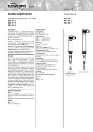
Systemkomponenten<br />
NRG 16-36<br />
Niveauelektrode NRG 16-36, PN 40<br />
Bauform<br />
<strong>NRS</strong> 19<br />
KunststoffSteckgehäuse für Schaltschrankeinbau. Nach Abziehen der Haube vom Gehäusesockel<br />
sind die Anschlussklemmen zugänglich. Die Verwechslung mit ähnlichen Geräten aus dem GESTRA<br />
Programm ist durch Codierstecker ausgeschlossen. Das Gerät eignet sich sowohl für Schnappbefestigung<br />
auf einer 35 mm Normschiene als auch zur Befestigung auf einer Montageplatte.
Technische Daten<br />
D<br />
<strong>NRS</strong> 19<br />
Bauteilkennzeichen<br />
TÜV · WR/WB · 04-370<br />
EG 01 202 931-B01-0075<br />
Eingang<br />
Acht Anschlüsse für eine Niveauelektrode NRG 16-36, PN 40<br />
Ausgang<br />
Begrenzerteil<br />
Zwei potentialfreie Umschaltkontakte.<br />
Reglerteil<br />
Ein potentialfreier Umschaltkontakt (nur Schließer) für Speiseeinrichtung EIN/AUS.<br />
Ein potentialfreier Umschaltkontakt für „Höchstwasserstand erreicht“.<br />
Kontaktmaterial Silber, hart vergoldet.<br />
Maximaler Schaltstrom bei Schaltspannungen 24 V, 115 V und 230 V AC: ohmsch 4A,<br />
induktiv 0,75 A bei cos j 0,5.<br />
Maximaler Schaltstrom bei Schaltspannung 24 V DC: 4A.<br />
Ansprechverzögerung<br />
NW-Begrenzer 1 s oder 3 s serienmäßig, bis max. 25 s auf Wunsch nach TÜV-Absprache.<br />
Regler 2 s, HW-Begrenzer 2 s serienmäßig fest eingestellt.<br />
Ansprechempfindlichkeit<br />
Umschaltbar mit DIP-Schalter.<br />
Bereich 1: 10 μS/cm bei 25 °C<br />
Bereich 2: 0,5 μS/cm bei 25 °C<br />
Anzeigen und Bedienungselemente<br />
Eine LED „Betrieb“, zwei LED „NW-Alarm“, eine Prüftaste „TEST 1“,<br />
ein Umschalter „TEST 2 / INSPECTION“, eine LED „Regler ein“, eine LED „HW-Alarm“ und<br />
ein vierpoliger Kodierschalter.<br />
Netzspannung<br />
230 V +/–10 %, 50/60 Hz (Spannung bei Bestellung angeben).<br />
Sonderspannung 115 V +/–10 %, 50/60 Hz oder 24 V +/–10 %, 50/60 Hz.<br />
Mit Zusatzgerät URN-1 auch Speisung mit 24 V Gleichspannung möglich.<br />
Schutzart<br />
IP 20 nach DIN 40050,<br />
Zulässige Umgebungstemperatur<br />
0 °C bis 55 °C<br />
Gehäusewerkstoffe<br />
Unterteil ABS, schwarz.<br />
Haube Polystyrol hochschlagfest, steingrau.<br />
Gewicht<br />
0,6 kg
Technische Daten Fortsetzung<br />
D<br />
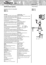
Korrosionsbeständigkeit<br />
Bei bestimmungsgemäßem Gebrauch wird die Sicherheit des Gerätes nicht durch Korrosion<br />
beeinträchtigt.<br />
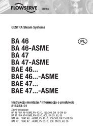
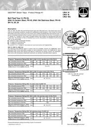
Typenschild / Kennzeichnung<br />
Bedienungsanweisung<br />
beachten<br />
See installation<br />
instructions<br />
Voir instructions de<br />
montage<br />
<strong>NRS</strong> 1-9b 230V<br />
50 / 60 Hz 5 VA 3 sec.<br />
-1<br />
0,5/10 µS/cm (c=0,13 cm )<br />
250 V ~ T 2,5 A<br />
Mat.Nr.: 390496<br />
GESTRA <strong>AG</strong><br />
Münchener Straße 77<br />
D-28215 Bremen<br />
Bedienungsanweisung<br />
beachten<br />
See installation<br />
instructions<br />
Voir instructions de<br />
montage<br />
<strong>NRS</strong> 1-9b 230V<br />
50 / 60 Hz 5 VA 3 sec.<br />
-1<br />
0,5/10 µS/cm (c=0,13 cm )<br />
250 V ~ T 2,5 A<br />
Mat.Nr.: 390496<br />
Fig. 1<br />
GESTRA <strong>AG</strong><br />
Münchener Straße 77<br />
D-28215 Bremen
Technische Daten Fortsetzung<br />
D<br />
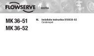
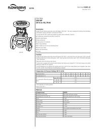
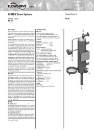
Maße<br />
158<br />
95<br />
75<br />
37,5<br />
120<br />
5<br />
Fig. 2 Fig. 3<br />
10
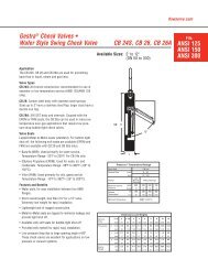
Aufbau<br />
D<br />
<strong>NRS</strong> 19<br />
F<br />
C<br />
B<br />
D<br />
D<br />
D<br />
E<br />
Fig. 4 Fig. 5<br />
F<br />
Fig. 6<br />
A<br />
11
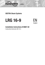
Funktionselemente<br />
D<br />
<strong>NRS</strong> 19<br />
1<br />
2<br />
3<br />
4<br />
5<br />
6<br />
G<br />
Fig. 7<br />
12
Aufbau/Funktionselemente<br />
D<br />
Legende<br />
A Haubenschraube<br />
B Haube<br />
C Unterteil<br />
D Kabeldurchführung<br />
E Schnappbefestigung<br />
F Bohrung für Wandbefestigung<br />
G DIP-Schalter für Ansprechempfindlichkeit<br />
1 LED „HW-Alarm“<br />
2 Umschalter „Test 2 / Inspection“<br />
3 LED „NW-Alarm“<br />
4 Prüftaste „Test 1“<br />
5 LED „PUMPE EIN“<br />
6 LED „Betrieb“<br />
13
Einbau<br />
D<br />
<strong>NRS</strong> 19<br />
Montageschiene vorhanden<br />
1. Temperaturschalter auf die Normschiene rasten.<br />
2. Haubenschrauben A lösen und Haube B vom Unterteil C abziehen.<br />
3. Kabeldurchführung D wählen und entsprechenden Verschluss durchstoßen.<br />
Montageschiene nicht vorhanden<br />
1. Haubenschrauben A lösen und Haube B vom Unterteil C abziehen.<br />
2. Schnappbefestigung E abschrauben.<br />
3. Vormarkierte Stelle F mit einem Bohrer ∅ 4,3 durchbohren.<br />
4. Kabeldurchführung D wählen und entsprechenden Verschluss durchstoßen.<br />
5. Unterteil mit zwei Schrauben M4 auf vorgesehener Grundplatte montieren.<br />
Werkzeug<br />
■ Schraubendreher (5,5/100)<br />
Legende<br />
A Haubenschraube<br />
B Haube<br />
C Unterteil<br />
F Bohrung für Wandbefestigung<br />
H Schnappbefestigung<br />
I Tragschiene TS 35 x 15 DIN EN 50022-35<br />
14
Einbau Fortsetzung<br />
D<br />
Einbaubeispiele<br />
H C<br />
B<br />
I<br />
A<br />
Fig. 8<br />
F<br />
F<br />
Fig. 9<br />
15
Elektrischer Anschluss<br />
D<br />
<strong>NRS</strong> 19<br />
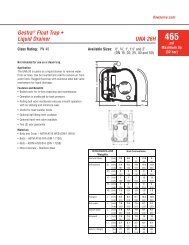
Für die Zuleitung ist vieradriges, abgeschirmtes Kabel erforderlich, z.B. IY(ST)Y 2 x 2 x 0,8 oder<br />
LIYCY 4 x 0,52. Länge maximal 250 m.<br />
Klemmleiste gemäß Anschlussplan belegen. Fig. 10<br />
Achtung<br />
■ Zum Schutz der Schaltkontakte Stromkreis mit Sicherung T 2,5 A absichern oder<br />
entsprechend der TRDVorschriften absichern (1A bei 72hBetrieb).<br />
■ Die Abschirmung darf keine galvanische Verbindung mit dem Schutzleiterpotential<br />
haben.<br />
Hinweis<br />
■ Abschirmung nur an Klemme 16 und 21 des Niveauschalters/-reglers anschließen.<br />
■ Die Nennspannung ist auf dem Typenschild angegeben.<br />
■ Beim Abschalten induktiver Verbraucher entstehen Spannungsspitzen, die die<br />
Funktion von Steuer- und Regelanlagen erheblich beeinträchtigen. Wir empfehlen<br />
deshalb, diese Verbraucher mit handelsüblichen RC-Kombinationen zu beschalten,<br />
z.B. 0,1 µF/100 Ω.<br />
Werkzeug<br />
■ SchlitzSchraubendreher Größe 2,5, vollisoliert nach DIN VDE 06801<br />
16
Elektrischer Anschluss Fortsetzung<br />
D<br />
Anschlussplan<br />
<strong>NRS</strong> 1-9<br />
1<br />
3<br />
2<br />
4<br />
Fig. 10<br />
NRG 16-36<br />
1<br />
4<br />
3<br />
2<br />
17
Grundeinstellung<br />
D<br />
Umschalten der Ansprechempfindlichkeit<br />
Der Niveauschalter kann auf zwei Ansprechempfindlichkeiten eingestellt werden.<br />
An der Rückseite des Gerätes befindet sich ein DIP-Schalter mit vier Einzelschaltern.<br />
Bereich 1: Ansprechempfindlichkeit ab 10 μS/cm (Werkseinstellung).<br />
Bereich 2: Ansprechempfindlichkeit ab 0,5 μS/cm.<br />
1. Gerät spannungsfrei schalten!<br />
2. Haubenschrauben A lösen und Haube B vom Unterteil C abziehen. Fig 8<br />
3. Alle vier Einzelschalter des DIP-Schalters G mit einer schmalen Schraubendreherklinge in den<br />
gewünschten Bereich schalten. Fig 7<br />
Werkzeuge<br />
n Schlitz-Schraubendreher Größe 2,5, vollisoliert nach VDE 0680<br />
Inbetriebnahme<br />
D<br />
Elektrischen Anschluss prüfen<br />
Prüfen Sie, ob <strong>NRS</strong> 1-9 mit der zugehörigen Systemkomponente NRG 16-36 gemäß dem Anschlussplan<br />
verdrahtet ist. Fig. 10<br />
Netzspannung einschalten<br />
Schalten Sie die Netzspannung ein. Die grüne 6 LED leuchtet. Fig. 6<br />
18
Funktionsprüfung<br />
D<br />
NW-Begrenzer<br />
1. Länge des Elektrodenstabs prüfen (siehe Einbauanleitung für NRG 16-36).<br />
2. Nach Anlegen der Netzspannung muss die grüne LED 6 ständig leuchten. Fig. 6<br />
3. Ventile der Wasserstandanzeiger am Dampferzeuger ganz öffnen.<br />
4. Dampferzeuger mit Speisewasser auffüllen (2cm über NWMarke).<br />
5. Speisewasser ablassen bis der niedrigste Wasserstand (NWMarke) unterschritten ist. Am<br />
Niveauschalter müssen nun nach Ablauf der Ansprechverzögerung die beiden roten LED 3<br />
aufleuchten.<br />
6. Sie können durch Drücken der Taste „TEST I“ 4 bei eingetauchter Elektrode einen NWAlarm<br />
simulieren. Drücken Sie die Taste so lange, bis die Ansprechverzögerung abgelaufen ist, beide<br />
roten LED 3 müssen dann aufleuchten.<br />
7. Die Selbsttesteinrichtung des Niveauschalters können Sie ebenfalls überprüfen.<br />
Bei eingetauchter Elektrode Prüfschalter „TEST II/INSPECTION“ 2 in Pfeilrichtung betätigen.<br />
Nach längstens zwei Minuten müssen die roten LED 3 NWAlarm signalisieren. Die Taste<br />
„TEST I“ 4 darf während dieser Prüfphase nicht betätigt werden, und Wassermangel<br />
darf nicht eintreten!<br />
Nach erfolgreicher Prüfung Schalter wieder in Ausgangsstellung zurückschalten.<br />
Die roten LED 3 müssen nach Ablauf der Ansprechverzögerung verlöschen.<br />
HW-Begrenzer<br />
1. Länge des Elektrodenstabs prüfen (siehe Einbauanleitung für NRG 16-36).<br />
2. Ventile der Wasserstandanzeiger am Dampferzeuger ganz öffnen.<br />
3. Dampferzeuger mit Speisewasser auffüllen, bis der höchstzulässige Wasserstand (HW-Marke)<br />
überschritten ist.<br />
Am Niveauschalter muss nun nach Ablauf einer Ansprechverzögerung von 2s die rote LED 1<br />
aufleuchten. Fig. 6<br />
4. Nach Absenken des Wasserstandes unter die HW-Marke muss die rote LED 1 erlöschen.<br />
Wasserstandregler<br />
1. Länge der Elektrodenstäbe prüfen (siehe Einbauanleitung für NRG 16-36).<br />
2. Wasserstand im Dampferzeuger soweit absenken, bis die Elektrode „2“ (unterer Schaltpunkt)<br />
vollkommen ausgetaucht ist. Fig. 10<br />
3. Die grüne LED 5 muss aufleuchten. Fig. 6<br />
Gleichzeitig wird die Schaltfunktion für die Speisepumpe ausgelöst (PUMPE EIN).<br />
4. Sobald der Wasserstand die Elektrode „3“ erreicht hat (oberer Schaltpunkt), erlischt die LED 5.<br />
Gleichzeitig wird die Schaltfunktion für die Speisepumpe ausgelöst (PUMPE AUS).<br />
19
Funktionsstörungen Betrieb<br />
D<br />
Warnung<br />
Die Klemmleiste des <strong>NRS</strong> 1-9 steht während des Betriebs unter Spannung!<br />
Schwere Verletzungen durch elektrischen Strom sind möglich!<br />
Vor Montage und Demontage des Gehäusedeckels Anlage spannungsfrei schalten!<br />
FehlerCheckliste Funktionsstörungen Betrieb<br />
Fehler:<br />
Abhilfe:<br />
Der Niveauschalter signalisiert NWAlarm, bevor der Wasserstand im Dampferzeuger die<br />
NWMarke erreicht hat.<br />
Überprüfen Sie das Maß des NWElektrodenstabes. Messen Sie die Leitfähigkeit des<br />
Prozess oder Kesselwassers und vergleichen Sie die Werte mit den Angaben auf dem<br />
Niveauschalter. Kontrollieren Sie, ob Niveauschalter und Elektrode gemäß Anschlussplan<br />
Fig. 10 verdrahtet wurden.<br />
Fehler: Nach Ansteigen des Wasserstandes über die NWMarke erlöschen die roten LED 3<br />
gar nicht oder erst nach längerer Zeit.<br />
Abhilfe: Überprüfen Sie, ob eine Ausgleichbohrung im Schaumschutzrohr vorhanden ist. Wenn die<br />
Elektrode in ein außenliegendes Messgefäß installiert ist, kontrollieren Sie die Stellung der<br />
Absperrventile.<br />
Fehler:<br />
Abhilfe:<br />
Fehler:<br />
Abhilfe:<br />
Fehler:<br />
Abhilfe:<br />
Eine oder beide roten LED 3 leuchtet, ohne dass der Wasserstand die NWMarke<br />
erreicht hat.<br />
Im Niveauschalter liegt Redundanzverlust vor, das heißt, ein oder zwei Steuerkanäle im<br />
Gerät sind ausgefallen. Niveauschalter auswechseln.<br />
Der Niveauschalter signalisiert HW-Alarm, bevor der Wasserstand im Dampferzeuger die<br />
HW-Marke erreicht hat.<br />
Überprüfen Sie das Maß des HW-Elektrodenstabes. Prüfen Sie, ob der Elektrodenstab<br />
Masseberührung hat. Kontrollieren Sie, ob Niveauschalter und Elektrode gemäß Anschlussplan<br />
Fig. 10 verdrahtet wurden.<br />
Nach Absenken des Wasserstandes erlöscht die rote LED 4 gar nicht oder erst nach<br />
längerer Zeit.<br />
Überprüfen Sie, ob eine Ausgleichbohrung im Schaumschutzrohr vorhanden ist. Wenn die<br />
Elektrode in ein außenliegendes Messgerät installiert ist, kontrollieren Sie die Stellung der<br />
Absperrventile.<br />
Falls Störungen oder Fehler auftreten, die mit dieser Betriebsanleitung nicht behebbar sind, wenden Sie<br />
sich bitte an unseren Technischen Kundendienst.<br />
Servicetelefon +49 (0)421/35 03444<br />
Servicefax +49(0)421/35 03199<br />
20
Anhang<br />
D<br />
Konformitätserklärung<br />
Für das Gerät <strong>NRS</strong> 19 erklären wir die Konformität mit folgenden europäischen Richtlinien:<br />
■ Niederspannungs-Richtlinie 2006/95/EG<br />
■ EMV-Richtlinie 89/336/EWG i. d. F. 93/68/EWG<br />
■ NSP-Norm EN 61010-1<br />
■ EMV-Norm EN 61000-6-2, EN 61000-6-4<br />
Bei einer nicht mit uns abgestimmten Änderung des Gerätes verliert diese Erklärung ihre Gültigkeit.<br />
Bremen, den 03. Januar 2005<br />
GESTRA <strong>AG</strong><br />
Dipl.Ing. Uwe Bledschun<br />
Leiter Konstruktion<br />
Dipl.Ing. Lars Bohl<br />
Qualitätsbeauftragter<br />
21
Contents<br />
Important Notes<br />
<br />
Page<br />
Usage for the intended purpose.............................................................................................................24<br />
Safety note............................................................................................................................................24<br />
Danger..................................................................................................................................................24<br />
Attention ..............................................................................................................................................24<br />
ATEX (Atmosphère Explosible)...............................................................................................................24<br />
Explanatory Notes<br />
Scope of supply.....................................................................................................................................24<br />
Description............................................................................................................................................25<br />
Function................................................................................................................................................25<br />
System components..............................................................................................................................25<br />
Design...................................................................................................................................................25<br />
Technical Data<br />
<strong>NRS</strong> 1-9................................................................................................................................................26<br />
Corrosion resistance..............................................................................................................................27<br />
Name plate / marking............................................................................................................................27<br />
Dimensions...........................................................................................................................................28<br />
Design<br />
<strong>NRS</strong> 1-9................................................................................................................................................29<br />
Key.......................................................................................................................................................31<br />
Functional Elements<br />
<strong>NRS</strong> 1-9................................................................................................................................................30<br />
Key.......................................................................................................................................................31<br />
Installation<br />
<strong>NRS</strong> 1-9................................................................................................................................................32<br />
Tools.....................................................................................................................................................32<br />
Key.......................................................................................................................................................32<br />
Examples of installation.........................................................................................................................33<br />
Wiring<br />
<strong>NRS</strong> 1-9................................................................................................................................................34<br />
Attention...............................................................................................................................................34<br />
Note......................................................................................................................................................34<br />
Tools.....................................................................................................................................................34<br />
Wiring diagram......................................................................................................................................35<br />
22
Contents – continued –<br />
Basic Adjustments<br />
<br />
Page<br />
Change-over for sensitivity....................................................................................................................36<br />
Tools.....................................................................................................................................................36<br />
Commissioning<br />
Check wiring.........................................................................................................................................36<br />
Apply power..........................................................................................................................................36<br />
Performance Tests<br />
Low-level limiter...................................................................................................................................37<br />
High-level limiter...................................................................................................................................37<br />
Water level controller.............................................................................................................................37<br />
Operational Malfunctions<br />
Danger..................................................................................................................................................38<br />
Fault-finding list for troubleshooting......................................................................................................38<br />
Annex<br />
Declaration of conformity......................................................................................................................39<br />
23
Important Notes<br />
<br />
Usage for the intended purpose<br />
Use level switch <strong>NRS</strong> 1-9 only in conjunction with level electrode NRG 16-36 for level control (high level<br />
alarm).<br />
Safety note<br />
The equipment must only be installed and commissioned by qualified and competent staff.<br />
Retrofitting and maintenance work must only be performed by qualified staff who – through adequate<br />
training – have achieved a recognised level of competence.<br />
Danger<br />
The terminal strip of the <strong>NRS</strong> 1-8 is live during operation. This presents the danger<br />
of electric shock!<br />
Cut off power supply before attaching or detaching the housing lid and the terminal<br />
strips of the equipment.<br />
Attention<br />
The name plate indicates the technical specification of the equipment.<br />
Do not commission or operate equipment without a name plate.<br />
ATEX (Atmosphère Explosible)<br />
The equipment constitutes a simple item of electrical equipment as defined in DIN EN 50020 section<br />
5.4. According to the European Directive ATEX 94/9/EC the equipment may only be used in potentially<br />
explosive atmosphers if it is provided with approved Zener barriers.<br />
Applicable in Ex zones 1, 2 (1999/92/EC). The equipment does not bear an EX marking. The suitability<br />
of the Zener barriers is certified in a separate document.<br />
Explanatory Notes<br />
<br />
Scope of supply<br />
<strong>NRS</strong> 19<br />
1 Water level controller/water level limiter (plug-in unit for installation in control cabinets)<br />
1 Installation manual<br />
24
Explanatory Notes – continued –<br />
<br />
Description<br />
Self-monitoring water level controller & limiter with automatic self-testing routine designed for use<br />
in conjunction with level electrode NRG 16-36. This equipment combination controls the water level,<br />
detects the max. allowable water level (high level alarm) and the min. allowable water level (low level<br />
alarm). Application in compliance with the German regulations for use in steam and hot-water plants<br />
according to TRD 602 and TRD 604, sheets 1 and 2.<br />
Function<br />
The switching controller <strong>NRS</strong> 1-9 features a two channel circuit and is provided with a self-monitoring<br />
and routine testing function in accordance with DIN 57116/VDE 0116. The two channels are designed<br />
to monitor the operation of each other (redundancy). The periodic self-checking logic unit checks the<br />
integrity of the cable between the electrode and the switching controller, and the two channel circuits<br />
for malfunction.<br />
Unless it finds a fault, this internal test does not interfere with the output contacts of the controller and<br />
therefore the boiler operation is not interrupted.<br />
A manual test push button is also provided. When the push button “TEST 1” is pressed, it simulates a<br />
fault in the electrode. There is also a toggle switch “TEST 2/Inspection” for checking the function of the<br />
self-checking circuitry. The output contact relays of the switching controller are of the normally closed<br />
type and will therefore signal alarm condition in the event of mains failure.<br />
The switching controller can signal the following four operating conditions:<br />
■ Normal operation (feedwater control)<br />
■ Alarm (high water level)<br />
■ Alarm (low water level)<br />
■ Alarm (fault in switching controller or level electrode)<br />
A green LED indicates power ON. Low water level alarm or malfunction of the low water level limiter<br />
system is indicated by the two red LEDs. The failure of one channel (loss of redundancy) is signalled by<br />
the lighting up of one red LED. The other green LED indicates feedwater pump is running. High water<br />
level alarm is signalled by another red LED.<br />
The use of SMART combination electrode NRG 16-36 in conjunction with switching controller <strong>NRS</strong> 1-9<br />
provides fail safe protection against a first fault, i. e. the system will still continue to provide the safety<br />
function even after the occurrence of a first fault.<br />
System components<br />
NRG 16-36<br />
Level electrode NRG 16-36, PN 40<br />
Design<br />
<strong>NRS</strong> 19<br />
Plug-in unit in plastic case for installation in control cabinets. The terminals in the case are accessible<br />
after loosening two screws and unplugging the unit from its base. To avoid confusion with other plug-in<br />
units of the GESTRA range, inserts are fitted in the bases so that only the correct unit may be plugged<br />
into each base. The plug-in unit may be snapped onto a 35 mm supporting rail or screwed into position<br />
on a mounting panel.<br />
25
Technical Data<br />
<br />
<strong>NRS</strong> 19<br />
Type approval no.<br />
TÜV · WR/WB · 04-370<br />
EG 01 202 931-B01-0075<br />
Input<br />
8 connections for one level electrode NRG 16-36, PN 40<br />
Output contacts<br />
For level limiter part:<br />
Two volt-free relay contacts<br />
For level controller part:<br />
One volt-free working contact for feedwater on-off control.<br />
One volt-free relay contact for high level alarm.<br />
Contact material silver, hard gold plated.<br />
Max. contact rating with switching voltages of 24 V, 115 V and 230 V a.c.:<br />
4 A resistive, 0.75 A inductive at cos ϕ 0.5<br />
Max. contact rating with switching voltage of 24 V d.c.: 4 A<br />
Delay of response<br />
The low water level alarm signal is factory set to react after a time delay of<br />
1 or 3 seconds (up to 25 sec. delay is possible).<br />
The controller as well as the high water level alarm signal is factory set to react after a time delay of<br />
2 seconds.<br />
Sensitivity<br />
Range 1: 10 µS/cm at 25 °C<br />
Range 2: 0.5 µS/cm at 25 °C<br />
The selection of the above range is done via a code switch.<br />
Indicators and adjustors<br />
One green LED “Power”, two LEDs “Low level alarm”, one test button “TEST 1”, one toggle switch<br />
“TEST 2/INSPECTION”, one LED “Feedwater control on”, one LED “High level alarm” and one fourpole<br />
code switch.<br />
Mains supply<br />
230 V +/– 10 %, 50/60 Hz (please state voltage when ordering)<br />
Special voltage: 115 V +/– 10 %, 50/60 Hz or 24 V +/– 10 %, 50/60 Hz;<br />
24 V d. c. supply is also possible with the inverter type URN-1.<br />
Protection<br />
IP 20 in accordance with DIN 40050<br />
Admissible ambient temperature<br />
0 to 55 °C<br />
Case materials<br />
Base: ABS plastic, black. Cover: polystyrene, highly shock resistant, stone grey.<br />
Weight<br />
0.6 kg<br />
26
Technical Data – continued –<br />
<br />
Corrosion resistance<br />
If the equipment is used for its intended purpose, its safety is not impaired by corrosion.<br />
Name plate / marking<br />
Bedienungsanweisung<br />
beachten<br />
See installation<br />
instructions<br />
Voir instructions de<br />
montage<br />
<strong>NRS</strong> 1-9b 230V<br />
50 / 60 Hz 5 VA 3 sec.<br />
-1<br />
0,5/10 µS/cm (c=0,13 cm )<br />
250 V ~ T 2,5 A<br />
Mat.Nr.: 390496<br />
GESTRA <strong>AG</strong><br />
Münchener Straße 77<br />
D-28215 Bremen<br />
Bedienungsanweisung<br />
beachten<br />
See installation<br />
instructions<br />
Voir instructions de<br />
montage<br />
<strong>NRS</strong> 1-9b 230V<br />
50 / 60 Hz 5 VA 3 sec.<br />
-1<br />
0,5/10 µS/cm (c=0,13 cm )<br />
250 V ~ T 2,5 A<br />
Mat.Nr.: 390496<br />
Fig. 1<br />
GESTRA <strong>AG</strong><br />
Münchener Straße 77<br />
D-28215 Bremen<br />
27
Technical Data – continued –<br />
<br />
Dimensions<br />
158<br />
95<br />
75<br />
37.5<br />
120<br />
5<br />
Fig. 2 Fig. 3<br />
28
Design<br />
<br />
<strong>NRS</strong> 19<br />
F<br />
C<br />
B<br />
D<br />
D<br />
D<br />
E<br />
Fig. 4 Fig. 5<br />
F<br />
Fig. 6<br />
A<br />
29
Functional Elements<br />
<br />
<strong>NRS</strong> 19<br />
1<br />
2<br />
3<br />
4<br />
5<br />
6<br />
G<br />
Fig. 7<br />
30
Design / Functional Elements<br />
<br />
Key<br />
A Cover screws<br />
B Cover<br />
C Base<br />
D Cable entry<br />
E Mounting clip<br />
F Hole for wall mounting<br />
G Code switch for setting sensitivity<br />
1 LED “High level alarm”<br />
2 Switch “Test 2 / Inspection”<br />
3 LED “Low level alarm”<br />
4 Test button “Test 1”<br />
5 LED “Pump ON”<br />
6 LED “Power”<br />
31
Installation<br />
<br />
<strong>NRS</strong> 19<br />
On supporting rail<br />
1. Snap switching controller onto supporting rail.<br />
2. Loosen cover screws A and unplug cover B from its base C.<br />
3. Select cable entry D and remove corresponding seal.<br />
On mounting panel<br />
1. Loosen cover screws A and unplug cover B from its base C.<br />
2. Unscrew mounting clip E.<br />
3. Drill the hole F marked in the base to 4.3 mm diameter.<br />
4. Select cable entry D and remove corresponding seal.<br />
5. Fasten base with two screws M4 onto mounting panel.<br />
Tools<br />
■ Screwdriver (5.5/100)<br />
Key<br />
A Cover screws<br />
B Cover<br />
C Base<br />
F Hole for wall mounting<br />
H Mounting clip<br />
I Support rail TS 35 x 15 to DIN EN 50022-35<br />
32
Installation – continued –<br />
<br />
Examples of installation<br />
H C<br />
B<br />
I<br />
A<br />
Fig. 8<br />
F<br />
F<br />
Fig. 9<br />
33
Wiring<br />
<br />
<strong>NRS</strong> 19<br />
Use four-core overall screened cable, e. g. IY(ST)Y 2 x 2 x 0.9 or LIYCY 4 x 0.5 mm².<br />
Max. cable length 250 m.<br />
Connect terminal strip in accordance with wiring diagram, fig. 10<br />
Attention<br />
■ To protect the switching contacts fuse circuit with 2.5 A (slow blow fuse) or according<br />
to TRD regulations (1.0 A for 72 hrs operation).<br />
■ The screen must not make any other electrical contact.<br />
Tools<br />
Note<br />
■ Connect screen only to terminals 16 and 21 of the switching controller.<br />
■ The mains voltage is indicated on the name plate.<br />
■ When switching off inductive loads, voltage spikes are produced that may impair the<br />
operation of control and measuring systems. Inductive loads should be provided with<br />
commercial arc suppressor RC combinations, e. g. 0.1 ΩF/100 W.<br />
■ Screwdriver for slotted screws, size 2.5, completely insulated according to VDE 0680.<br />
34
Wiring – continued –<br />
<br />
Wiring diagram<br />
<strong>NRS</strong> 1-9<br />
1<br />
3<br />
2<br />
4<br />
Fig. 10<br />
NRG 16-36<br />
1<br />
4<br />
3<br />
2<br />
35
Basic Adjustments<br />
<br />
Change-over for sensitivity<br />
The switching controller can be set to two different sensitivities. For this purpose a code switch<br />
consisting of four individual switches is provided on the rear of the controller.<br />
Range 1: Sensitivity from 10 µS/cm (factory setting)<br />
Range 2: Sensitivity from 0.5 µS/cm<br />
1. Cut off power supply to switching controller.<br />
2. Loosen cover screws A and unplug cover B from its base C, fig. 8<br />
3. Move all four individual switches of the code switch G to the desired range using a small<br />
screwdriver, fig. 7.<br />
Tools<br />
n Screwdriver for slotted screws, size 2.5, completely insulated according to VDE 0680.<br />
Commissioning<br />
<br />
Check wiring<br />
Check whether switching controller <strong>NRS</strong> 1-9 and the associated electrode NRG 16-36 are wired in<br />
accordance with wiring diagram, fig. 10<br />
Apply power<br />
Apply mains voltage. The green LED 6 lights up, fig. 6<br />
36
Performance Tests<br />
<br />
Low-level limiter<br />
1. Check length of electrode tip (see installation instructions for NRG 16-36).<br />
2. When switching on the mains voltage the green LED 6 should light permanently, fig. 6.<br />
3. Completely open valves of water-level gauge glass on steam boiler.<br />
4. Fill boiler with feedwater (2 cm above required min. level).<br />
5. Decrease level in boiler until the level falls below min. level. After the response delay the two red<br />
LEDs 3 must light up.<br />
6. A low-level alarm can be simulated by pushing the button “TEST I” 4 whilst the electrode tip<br />
is submerged. Push the button until the response delay has expired. Both red LEDs 3 must<br />
light up.<br />
7. To check the function of the checking circuitry of the switching controller proceed as follows:<br />
Operate switch “TEST II / INSPECTION” 2 in the direction of the arrow with the electrode tip<br />
submerged. After max. two minutes the two red LEDs 3 should signal low-level alarm.<br />
The button “TEST I” 4 must not be operated during this test nor must the level fall below the low<br />
level mark.<br />
After the test return switch into its original position. After the response delay the two red LEDs 3<br />
must extinguish.<br />
High-level limiter<br />
1. Check length of electrode tip (see installation instructions for NRG 16-36).<br />
2. Completely open valves of water-level gauge glass on steam boiler.<br />
3. Fill boiler with feedwater until the level exceeds the required max. level.<br />
After the response delay of 2 sec. the red LED 1 must light up, fig. 6.<br />
4. Decrease level in the boiler until the level falls below high level, the red LED 1 must extinguish.<br />
Water level controller<br />
1. Check length of electrode tips (see installation instructions for NRG 16-36).<br />
2. Lower water level in boiler until electrode tip “2” (lower switch point) is completely exposed, fig. 10.<br />
3. The green Led 5 must light up, fig. 6.<br />
Simultaneously the switching function for feedwater control (PUMP ON) is released.<br />
4. When the water level reaches electrode tip “3” (upper switch point), LED 5 must extinguish.<br />
Simultaneously the switching function for feedwater control (PUMP OFF) is released.<br />
37
Operational Malfunctions<br />
<br />
Danger<br />
The terminal strip of the <strong>NRS</strong> 1-9 is live during operation. This presents the danger<br />
of electric shock!<br />
Cut off power supply before fixing or removing the housing cover.<br />
Fault finding list for troubleshooting<br />
Fault:<br />
Remedy:<br />
Fault:<br />
Remedy:<br />
Fault:<br />
Remedy:<br />
Fault:<br />
Remedy:<br />
Fault:<br />
Remedy:<br />
The switching controller signals low-level alarm before the level in the boiler has fallen<br />
below the low level mark.<br />
Check length of low-water level electrode tip. Measure the conductivity of the process or<br />
boiler water and compare the values obtained with the marking on the name plate.<br />
Check correct wiring of switching controller and electrode in accordance with wiring<br />
diagram, fig. 10.<br />
After raising the water level above the low-level mark, the red LEDs 3 are not<br />
extinguished or only after quite a considerable period.<br />
Check whether a vent hole has been provided in the protection tube. If the electrode is<br />
fitted in an external chamber, check position of isolating valves.<br />
One or both red LED(s) 3 light up without the level having fallen below the low-level<br />
mark.<br />
This means electronic failure within the switching controller, i. e. failure of one or both<br />
channels. Replace switching controller.<br />
The switching controller signals high-level alarm before the level in the boiler has reached<br />
the high level mark.<br />
Check length of high water level electrode tip. Check whether the electrode tip has contact<br />
with the chamber/protection tube or other boiler internals. Check correct wiring of level<br />
switch and electrode in accordance with wiring diagram, fig. 10.<br />
After decreasing the water level below the high-level mark, the red LED 4 is not<br />
extinguished or only extinguishes after quite a considerable period.<br />
Check whether a vent hole has been provided in the protection tube. If the electrode is<br />
fitted in an external chamber, check position of isolating valves.<br />
If faults occur that are not listed above please contact our subsidiary or agency in your country.<br />
38
Annex<br />
<br />
Declaration of conformity<br />
We hereby declare that the equipment <strong>NRS</strong> 1-9 conforms to the following European guidelines:<br />
■ LV guideline 73/23/eec version 93/68eec<br />
■ EMC guideline 89/336/eec version 93/68/eec<br />
■ LV standard EN 61010-1<br />
■ EMC standard EN 61000-6-2, EN 61000-6-4<br />
This declaration is no longer valid if modifications are made to the equipment without consultation<br />
with us.<br />
Bremen, 03 rd January 2005<br />
GESTRA <strong>AG</strong><br />
Head of the Design Dept.<br />
Uwe Bledschun<br />
(Academically qualified engineer)<br />
Quality Assurance Manager<br />
Lars Bohl<br />
(Academically qualified engineer)<br />
39
GESTRA<br />
Vertretungen weltweit · Agencies all over the world<br />
www.gestra.de<br />
España<br />
GESTRA ESPAÑOLA S.A.<br />
Luis Cabrera, 86-88<br />
E-28002 Madrid<br />
Tel. 00 34 91 / 5 15 20 32<br />
Fax 00 34 91 / 4 13 67 47; 5 15 20 36<br />
E-mail: aromero@flowserve.com<br />
Polska<br />
GESTRA Polonia Spolka z.o.o.<br />
Ul. Schuberta 104<br />
PL - 80-172 Gdansk<br />
Tel. 00 48 58 / 3 06 10 -02 od 10<br />
Fax 00 48 58 / 3 06 33 00<br />
E-mail: gestra@gestra.pl<br />
Great Britain<br />
Flowserve Flow Control (UK) Ltd.<br />
Abex Road<br />
Newbury, Berkshire RG14 5EY<br />
Tel. 00 44 16 35 / 4 69 99<br />
Fax 00 44 16 35 / 3 60 34<br />
E-mail: gestraukinfo@flowserve.com<br />
Portugal<br />
Flowserve Portuguesa, Lda.<br />
Av. Dr. Antunes Guimarães, 1159<br />
Porto 4100-082<br />
Tel. 0 03 51 22 / 6 19 87 70<br />
Fax 0 03 51 22 / 6 10 75 75<br />
E-mail: jtavares@flowserve.com<br />
Italia<br />
Flowserve S.p.A.<br />
Flow Control Division<br />
Via Prealpi, 30<br />
l-20032 Cormano (MI)<br />
Tel. 00 39 02 / 66 32 51<br />
Fax 00 39 02 / 66 32 55 60<br />
E-mail: infoitaly@flowserve.com<br />
USA<br />
Flowserve GESTRA U.S.<br />
2341 Ampere Drive<br />
Louisville, KY 40299<br />
Tel.: 00 15 02 / 267 2205<br />
Fax: 00 15 02 / 266 5397<br />
E-mail: dgoodwin@flowserve.com<br />
GESTRA <strong>AG</strong><br />
P. O. Box 10 54 60, D-28054 Bremen<br />
Münchener Str. 77, D-28215 Bremen<br />
Telephone +49 (0) 421 35 03 - 0<br />
Fax +49 (0) 421 35 03 - 393<br />
E-Mail gestra.ag@flowserve.com<br />
Internet www.gestra.de<br />
808394-02/607cs · 2007 GESTRA <strong>AG</strong> · Bremen · Printed in Germany<br />
40