Umschlag Bus_GB.qxd - FAST Spec
Umschlag Bus_GB.qxd - FAST Spec
Umschlag Bus_GB.qxd - FAST Spec

You also want an ePaper? Increase the reach of your titles
YUMPU automatically turns print PDFs into web optimized ePapers that Google loves.
Planning and<br />
Installation<br />
The system bus becomes<br />
Siedle-In-Home<br />
• Siedle system bus<br />
door and in-house<br />
telephony<br />
• Siedle system bus<br />
door and in-house<br />
telephony with video<br />
• Siedle-In-Home<br />
• DoorCom<br />
Issue 2002/2003
Contents<br />
Siedle system bus<br />
for door and in-house telephony<br />
Siedle system bus<br />
Application / general 4<br />
Performance features<br />
Installation<br />
Conductor materials, ranges 8<br />
Licht actuation via light current relay<br />
Light actuation via time relay ZR 502-0 9<br />
Terminal comparison BTLM 650-... with BTLE 050-...<br />
DIM 611-... for calls in the Siedle system bus<br />
Contact assignment VAR 602-... 10<br />
Connecting the anti-pilfer safeguard<br />
Connecting the NS 511-... with BSM 650-....<br />
Connecting the BNS 750-... 11<br />
Connecting the BSE 650-...<br />
Connecting the BEM 650-...<br />
Accessories, buttons, switches, lamp 12<br />
Connecting the BTLM 650-... 13<br />
Explanation of the circuit diagram abbreviations<br />
Terminal explanation BTLM 650-... / STL...<br />
Terminal explanation BTS/BTC 750-...<br />
Terminal explanation DCA 650-... with DCSF 600-...<br />
Terminal explanation DCI 650-... / DCIV 600-... 14<br />
AS-TYR-1/1<br />
Single line system with BTLM 650-... 15<br />
AS-TYR-1/1<br />
Single line system with BTLE 050-... 16<br />
AS-TYR-1/1<br />
Single line system with BSM 650-... 17<br />
AS-TYR-1/1<br />
Single line system with digital call via DIM/COM 611-... 18<br />
AS-TYR-n/n<br />
Multiple-line system 19<br />
Siedle system bus<br />
Video components<br />
Application / general<br />
Determining the most suitable camera<br />
Video camera location<br />
Video camera pick-up range 20<br />
Connecting the ZDMO 950-...,<br />
Block diagram ZDMO 950-...<br />
Video technology in the Siedle system bus<br />
Video components in the Siedle system bus<br />
Range in the system bus 23<br />
Conductor routing<br />
Ranges with coaxial cable<br />
Table of different coaxial cable types 24<br />
Line rectifier loads<br />
System monitors in parallel operation<br />
Module connection at the Vario door station 25<br />
Connecting the coaxial cable to the monitor and camera<br />
Terminal comparison VBS 650-... with VBSM 650-...<br />
Internal wiring BTS/BTC 750-... and MOM/MOC 711-... 26<br />
Internal wiring of the BTS/BTC 750/... and MOCT 711-..<br />
Comparison of cameras 27<br />
Siedle system bus with video door telephony<br />
ÜV-TVYR-1/1 28<br />
AS-TVYR-1/1<br />
Single line system with one video door station 29<br />
AS-TVYR-1/2<br />
Single line system with two video door stations 30<br />
Connection of MOM/MOC 711-... with ZVM 711-...<br />
or MOCT 711-... 31<br />
AS-TVYR-n/n<br />
Door telephony with video in the multiple-line Siedle<br />
system bus with one camera per line 32/33<br />
Video door telephony with coax<br />
ÜV-TVKYR-1/1 34<br />
AS-TVKYR-1/1<br />
Single line system with video coax<br />
and one video door station 35<br />
AS-TVKYR-1/2<br />
Single line system with video coax<br />
and two video door stations 36<br />
AS-TVKYR-n/n<br />
Multiple-line system with video coax<br />
and one video door station per line 38-40
3<br />
Siedle-In-Home bus<br />
Application / general 42<br />
System structure<br />
Performance features<br />
Conductor materials, ranges<br />
Attenuation values 46<br />
Attenuation values BVVS / BVVU / BAA 650-... 47<br />
Schematic diagram with camera branch and<br />
monitor branch 48<br />
Attenuation calculation examples 49<br />
Terminal assignment BSE 650-...<br />
Terminal assignment BEM 650-... 50<br />
Connecting the BAA 650-...<br />
Connecting the BVVS 650-...<br />
Connecting the BVVU 650-... 51<br />
Pre-installation Vario door station 52<br />
Wiring the apartment stations 53-55<br />
Siedle-In-Home bus<br />
Door telephony with video as a single-line system<br />
ÜV-TVH-1/1 56<br />
AS-TVH-1/1<br />
Single-line system in family homes with self-contained flat 57<br />
AS-TVH-1/1<br />
Single-line system in apartment buildings 58<br />
Siedle-In-Home bus<br />
Door telephony with video as a single-line system<br />
with several rising mains<br />
ÜV-TVH-n/n 59<br />
AS-TVH-1/n<br />
Several door loudspeakers 60<br />
AS-TVH-n/n<br />
One-line system with several rising mains 61<br />
DoorCom<br />
DoorCom analog DCA 650-...<br />
DoorCom switching/remote control interface DCSF 600-...<br />
Terminal assignment DCA 650-... with<br />
integrated DCSF 600-... 62<br />
AS-TYR-1/1<br />
with DCA 650-... and DCSF 600-... 63<br />
AS-TVYR-1/1 with video and<br />
with DCA 650-... and DCSF 600-... 64/65<br />
AS-TVKYR-1/1 with video via coax<br />
with DCA 650-... and DCSF 600-... 65/66<br />
Siedle-In-Home bus with DCA 650-02<br />
AS-TVH-1/1 67<br />
DoorCom-ISDN DCI 600-0 and DCIV 600-0<br />
DoorCom switching/remote control interface DCI 600-...<br />
Terminal assignment DCI 600-... 68<br />
Siedle system bus with DCI<br />
AS-TYR-1/1 with DCI-... 69<br />
Siedle system bus with DCI and video transmission<br />
also via MOM/MOC as a parallel unit<br />
AS-TVYR-1/1 with DCI/DCIV 600-... 69/70<br />
AS-TVKYR-1/1 with DCI 600-...,<br />
without video transmission to the outside 69/71<br />
Siedle-In-Home bus with DCI and video transmission<br />
also via MOM/MOC as a parallel unit<br />
AS-TVH-1/1 with DCI/DCIV 600-... and MOCT 711-... 72<br />
Additional Siedle planning documentation<br />
is available from the factory<br />
„Planning and Installation Telecommunication“<br />
„Planning and Installation Intercom Systems“<br />
Part 1 and Part 2<br />
Remark<br />
Technical additions and<br />
printing errors do not constitute<br />
grounds for claims to<br />
damages
Siedle system bus<br />
for door and in-house telephony<br />
Planning and installation<br />
Performance features<br />
Calling/speech/door release/audio privacy<br />
Storey call with call differentiation<br />
Light control<br />
Secondary signal unit<br />
Door release time<br />
No. of door stations<br />
Number of lines 15<br />
Number of users per line 31<br />
Siedle system bus<br />
with BTS/BTC 750-...<br />
•<br />
Max. no. of users 465<br />
Speech circuits<br />
Call silencing<br />
Stepless call volume<br />
regulation<br />
Video link<br />
Storey door loudspeaker<br />
with call differentiation<br />
Internal communication incl. audible tones<br />
Switching/control function<br />
Display LEDs<br />
Direct, selective door dialling incl.<br />
video actuation<br />
Digital call input possible (COM/DIM)<br />
no additional installation required<br />
via BNS 750-... or standard<br />
signalling device via BSM/BSE 650-..<br />
and additional installation<br />
3 secs. fixed<br />
max. bus users less<br />
the connected BSM/BSE 650-...<br />
BTS/BTC 750-..., BNS 750-...<br />
1 per line<br />
•<br />
•<br />
•<br />
•<br />
•<br />
•<br />
• with additional installation<br />
•<br />
• BIM 650-... required<br />
Application<br />
The Siedle system bus is a highperformance,<br />
comprehensive<br />
bus system. In this system, the<br />
customary performance feaures<br />
of calling, speech, door release<br />
and light switching are<br />
supplemented by additional<br />
control functions. At the<br />
BTC 750-... it is possible to<br />
make interal calls, dial specific<br />
doors, or execute control<br />
functions in conjunction with<br />
additional units using 6<br />
integrated freely programmable<br />
buttons. There are also<br />
two integrated LEDs available<br />
for display purposes. The LEDs<br />
are actuated via a separate<br />
installation with 12 V AC and a<br />
common reference point „La“.<br />
General<br />
Circuit diagrams are provided<br />
in the form of:<br />
Single-line or multiple-line<br />
systems.<br />
Single-line or multiple line<br />
systems with video bus,<br />
alternatively with video coaxial<br />
transmission. Additional<br />
functions are also possible. For<br />
this, refer to the detail circuit<br />
diagrams on pages 9 -11.<br />
Siedle audio/video components<br />
System users<br />
BTLM 650-... <strong>Bus</strong> door loudspeaker module 2<br />
BTLE 050-... <strong>Bus</strong> custom-fit door loudspeaker 2<br />
BTM 650-... <strong>Bus</strong> button module<br />
BRMA 050-... <strong>Bus</strong> call button matrix<br />
BTS 750-... <strong>Bus</strong> telephone, standard •<br />
BTC 750-... <strong>Bus</strong> telephone, de-luxe •<br />
BNS 750-... <strong>Bus</strong> secondary signalling unit •<br />
BSG 650-... <strong>Bus</strong> control unit<br />
BSM 650-... <strong>Bus</strong> switching module •<br />
BVG 650-... <strong>Bus</strong> supply unit<br />
BIM 650-... <strong>Bus</strong> interface module<br />
BSE 650-... <strong>Bus</strong> switching unit •<br />
BEM 650-... <strong>Bus</strong> input module •<br />
MOCT 711-... Touchscreen colour monitor •<br />
BTLM 650-02 and STL ...<br />
BTLM 650-... in the Vario<br />
design STL ... Siedle steel door<br />
station with stainless steel<br />
function panel is always<br />
supplied as a complete system<br />
and cannot be subsequently<br />
upgraded. Door loudspeaker<br />
for the Siedle system bus.<br />
Connection to the terminals<br />
and call button modules takes<br />
place via ribbon cable. Camera<br />
actuation and triggering from<br />
COM/DIM 611 are integrated.<br />
Illuminated light button to<br />
actuate a floating working<br />
contact and as a programming<br />
button. Integrated working<br />
contact from each BTS/BTC can<br />
be actuated as a door release<br />
contact. After placement of a<br />
call, the door loudspeaker<br />
remains connected to the<br />
system for appr. 45 seconds.<br />
<strong>Spec</strong>ifications<br />
Door release contact load<br />
24 V/2 A DC/AC<br />
Door release ON time: fixed<br />
at 3 seconds.<br />
Note!<br />
Up to 40 call button modules<br />
can be connected irrespective<br />
of the number of call buttons<br />
per BTM. With more than 160<br />
users, the DIM/COM 611-...<br />
must be used with the<br />
BIM 611-... .<br />
Programming<br />
via PC, / in small systems<br />
1-man programming possible
5<br />
BTM 650-...<br />
<strong>Bus</strong> call button module<br />
BTM 650-.. as a 1, 2, 3 or 4<br />
button module with terminal<br />
adapter. Connection from one<br />
BTM to the next takes place<br />
using the provided ribbon cable<br />
with plug.<br />
TB 611-...<br />
Power-saving, maintenancefree<br />
LED call button module<br />
lighting to be simply<br />
exchanged with the integrated<br />
tubular lamp.<br />
<strong>Spec</strong>ifications<br />
Supply 12 V AC /30 mA<br />
BTLE 050-02<br />
Custom fit door loudspeaker<br />
for the Siedle bus system. With<br />
controller for the loudspeaker.<br />
For connection of the user’s<br />
own call buttons (selfcleaning),<br />
a bus call button<br />
matrix BTMA 050-... is always<br />
required. Integrated camera<br />
actuation and programming<br />
button for entry into the<br />
programming level. Integrated<br />
working contact from each<br />
BTS/BTC can be actuated as a<br />
door release contact. Universal<br />
fixture possibilities.<br />
Louvre accessory ZJ 051-... can<br />
be screwed on directly if used.<br />
<strong>Spec</strong>ifications<br />
Contact load 24 V/2 A<br />
DC /AC.<br />
Important<br />
To connect external call<br />
buttons, the bus call button<br />
matrix BRMA 050-... is always<br />
required. BTM 650-... cannot<br />
be connected.<br />
BRMA 050-...<br />
<strong>Bus</strong> call button matrix for<br />
connection of max. 12 of the<br />
user’s own call buttons (selfcleaning)<br />
as encapsulated<br />
electronic circuit for connection<br />
with 13-pin terminal strip,<br />
ribbon cable and 2 plug-in<br />
sockets for connection to the<br />
BTLE and the next<br />
BRMA 050-... A maximum of<br />
14 BRMA units can be<br />
connected to a BTLE 050-... .<br />
BTS 750-02<br />
<strong>Bus</strong> telephone standard for<br />
door telephony with the bus<br />
door loudspeakers<br />
BTLM 650-... / BTLE 050-...,<br />
made of high-grade anti-static<br />
plastic. With the basic<br />
functions calling, speech, door<br />
release, light and storey call.<br />
Performance features:<br />
• Hearing protection, audio<br />
and video privacy function and<br />
call silencing integrated.<br />
• Parallel connection of max. 2<br />
bus telephones without<br />
internal speech operation<br />
• Call generator with call<br />
differentiation for storey calls,<br />
2 door calls<br />
• Stepless adjustment of call<br />
volume up to max. 83 dB(A).<br />
• Door release/light function at<br />
any time via the bus line<br />
• Door/video connection at any<br />
time, also without a preceding<br />
door call, by double clicking<br />
the light button to the last<br />
called door loudspeaker.<br />
• Plug-in spiral cable for simple<br />
installation of the telephone<br />
receiver.<br />
• Facility for in-row mounting<br />
of monochrome or colour<br />
monitors<br />
• For use as flush or table top<br />
mounted unit with the relevant<br />
accessories.<br />
BTC 750-02<br />
<strong>Bus</strong> telephone deluxe for door<br />
and internal telephony,<br />
included in the basic<br />
performance scope as<br />
BTS 650-02.<br />
The BTC 750-... is capable of<br />
internal calls and speech<br />
within one line.<br />
Additional performance<br />
features:<br />
• Audible tones for internal<br />
communication<br />
• Call differentiation for<br />
internal calls<br />
• 2 LEDS for display purposes<br />
(e.g. door open) with<br />
additional wiring.<br />
• 6 integrated function keys.<br />
Functions of the keys can be<br />
optionally assigned and<br />
initiated without any additional<br />
installation via the system bus,<br />
e.g.<br />
- for internal call buttons<br />
or<br />
- to initiate switching/control<br />
functions in conjunction with<br />
BSM/BSE 650-...<br />
or<br />
- Selective dialling of up to 6<br />
door loudspeakers<br />
• Integrated inscription panel<br />
for function keys.<br />
Remark<br />
BTS/BTC 750-... are not<br />
compatible with other<br />
telephones (systems).<br />
Important!<br />
When using table-top<br />
accessory ZT 711-0/4 an N<br />
coded junction box such as the<br />
AD 711-0/4 must be used.<br />
Call silencing<br />
With bus telephones BTS/<br />
BTC 750-... it is possible to<br />
implement a call silencing<br />
function by lifting the receiver<br />
and placing it in the bracket.<br />
The last call must have been<br />
terminated for at least 40 secs.<br />
/ the telephone must not have<br />
rung for the last 40 seconds.<br />
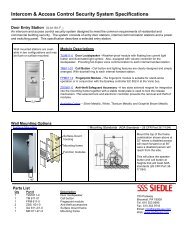
Flush mount combinations<br />
Unit Flush-mounting Flush-mount Dimensions<br />
combinations frame accessory housing acc. W H D<br />
mm<br />
BTS/BTC 750-... ZUR 611-01 GE 611-0 123 268 46<br />
BTS/BTC 750-...+ ZUR 3000-3 GE 611-0 + 300 268 51<br />
MOM/MOC/ 2 GZ 611-1+<br />
MOCT 711-... 2 GZ 611-3<br />
BTS/BTC 750-....+ ZUR 611-10/3 GE 611-0 + 364 268 51<br />
MOM/MOC/ 2 x GZ 611-1+<br />
MOCT 711-...+ GZ 611-2<br />
VBE/BVE 650-...<br />
MOM/MOC/ ZUR 3000-1 GE 611-0 + 211 268 51<br />
MOCT 711-... GZ 611-1 +<br />
GZ 611-3<br />
Each flush mounting frame<br />
accessory ZUR 611-... is<br />
supplied in the corresponding<br />
colour including cover strips.<br />
Installing the flush-mount<br />
housing<br />
Assemble the required flushmount<br />
housing configuration.<br />
Break out the required cable<br />
entries and grout in the<br />
housing.<br />
Note!<br />
Do not remove the mouldedon<br />
plaster protection. See<br />
product information.
Siedle system bus<br />
for door and in-house telephony<br />
Planning and installation<br />
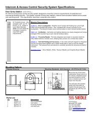
Mounting with hollow wall<br />
fastening accessory<br />
A hollow wall fastening<br />
accessory ZHB 611-...<br />
comprises two pairs of<br />
retaining brackets and screws.<br />
Cut-out dimensions and<br />
required number of hollow<br />
wall fastening accessories<br />
Flush-mounting Cut-out dimension Hollow wall f. accessory<br />
frame accessory (W x H) mm Packs/pairs<br />
ZUR 611-01 98 x 254 1/ 2<br />
ZUR 3000-3 276 x 254 1/2<br />
ZUR 611-10/3 342 x 254 2/2<br />
Combination for table-top<br />
mounting<br />
Unit<br />
combination<br />
Table-top accessory<br />
BTS/BTC 750-... ZT 711-0/4 +<br />
AD 711-0/4<br />
BTS/BTC 750-...+ ZT 711-01/16 +<br />
MOM/MOC/MOCT 711-... ZTMO 711-...<br />
ADs inclusive<br />
BTS/BTC 750-...+ ZT 711-01/16 +<br />
VBE 650-...+ ZMF 611-10 +<br />
MOM/MOC/MOCT 711-... ZTMO 650-0<br />
ADs inclusive<br />
BTS/BTC 750-...+ ZT 611-10 +<br />
BVE 650-...+ ZMF 611-10 +<br />
MOM/MOC/MOCT 711-... ZTMO 650-0 +<br />
AD 306-0<br />
MOM/MOC/MOCT 711-... ZTMO 611-0 +<br />
AD 501-01<br />
For how to mount, see product<br />
information ZUR ....<br />
NG 602-...<br />
The line rectifier in 6-grid<br />
switch panel housing provides<br />
the complete supply for up to<br />
31 system components<br />
(BTS/BTC/BNS 750-...,<br />
BTLM 650-... or BTLE 050-...).<br />
With more than 4 call button/<br />
info modules, an additional<br />
transformer TR 602-... must be<br />
provided for the lighting.<br />
Each line requires its own<br />
NG 602-...<br />
<strong>Spec</strong>ifications<br />
Primary: 230 V AC, 50/60 Hz,<br />
+6% -10%<br />
Secondary: 12 V AC - 1.6 A<br />
23.3 V DC - 0.3 A stabilized<br />
TR 602-...<br />
The transformer in the 6-grid<br />
switch panel housing for<br />
supplying for example the<br />
lighting, door release etc. with<br />
12 V AC.<br />
<strong>Spec</strong>ifications<br />
Primary: 230 V AC, 50/60 Hz,<br />
+6% -10%<br />
Secondary: 12 V AC - 2.5 A<br />
BSG 650-02<br />
<strong>Bus</strong> control unit BSG 650-...<br />
for switch panel mounting, the<br />
control unit for max. 31 system<br />
components in one line.<br />
Max. 15 lines can be<br />
connected to create one<br />
system.<br />
It is supplied by the NG 602-...<br />
with 24 V DC. For door release<br />
/ central light actuation, the<br />
BSG 650-... is fitted with one<br />
relay each with one 24 V 2A<br />
working contact.<br />
Door release switching time<br />
fixed at 3 seconds<br />
Light contact switching time<br />
fixed at 0.5 secs.<br />
Each BSG 650-... requires its<br />
own NG 602-... as a power<br />
supply.<br />
Operating elements<br />
• Button to switch on the<br />
programming mode for all<br />
connected bus users.<br />
• LED to display different<br />
statuses also during<br />
programming.<br />
• Rotary switch for setting the<br />
address (1-9 / A-F).<br />
Remember that each<br />
address may only be<br />
assigned once in the system.<br />
The address „0“ is not<br />
admissible.<br />
The addresses are only set in<br />
ascending order where several<br />
lines are used.<br />
If only one line is used, the<br />
address is always 1.<br />
Using bus programming<br />
software BPS 650-0, it is now<br />
possible to program across<br />
several lines with the<br />
BSG 650-02. For this, the<br />
touchscreen colour monitor<br />
MOCT 711-0 or programming<br />
interface PRI 602-... in conjunction<br />
with the BIM 650-... is<br />
required.<br />
Note!<br />
Exchanging the BSG 650-...<br />
When exchanging the<br />
BSG 650-.. ensure that the<br />
device has not been previously<br />
installed. These devices have an<br />
„installation seal“ over the<br />
terminals Ta, Tb and Sa, Sb<br />
which must not be damaged or<br />
missing. Ensure that the<br />
address of the exchanged<br />
device is reset.<br />
Failure to observe this<br />
instruction can result in loss<br />
of the programming for the<br />
whole system.<br />
BPS 650-0<br />
<strong>Bus</strong> programming software for<br />
configuration of the<br />
touchscreen in the<br />
MOCT 711-... and the system<br />
bus users BTS/BTC 750-...,<br />
BNS 750-02 BTLM/<br />
BTLE 750-02, BSE/BEM/<br />
BSM 650-02.<br />
In the case of the DCA 650-02<br />
all functions can be programmed<br />
with the exception of<br />
public network functions such<br />
as calls, chain calls etc. For this,<br />
the programming interface<br />
PRI 602-... is required in<br />
conjunction with a BIM 650-...<br />
or if available in the system, the<br />
MOCT 711....<br />
BSM 650-02<br />
<strong>Bus</strong> switching module in a 3-<br />
grid switch panel housing with<br />
4 integrated relays, each with a<br />
floating working contact.<br />
Programmable functions:<br />
Actuation via the light button<br />
of the BTLM / the bus<br />
telephone, via the 6 buttons in<br />
the BTC or in parallel with a<br />
door call button to actuate an<br />
external signalling device.<br />
Performance features<br />
• Button for entry in the<br />
programming mode and for<br />
fixing the relay switching time<br />
(1 to 10 secs.).<br />
• Pick-up/switching time for<br />
each relay adjustable from 1 to<br />
10 seconds<br />
• 4 LEDs which indicate during<br />
programming which relay is<br />
currently selected. In the<br />
operating mode, the status of<br />
the relays is displayed.<br />
• Power supply<br />
12 V AC, e.g. by NG 602-... or<br />
TR 602-...<br />
• Bias current 50 mA<br />
• Operating current per relay<br />
60 mA<br />
• Contact load<br />
max. 24 V AC/DC, 2 A<br />
Each contact may only be<br />
programmed for one<br />
function.<br />
Actuation at any time also with<br />
the receiver down. The<br />
BSM 650-... is a system user in<br />
the same way as a BT.
7<br />
BSE 650-0<br />
<strong>Bus</strong> switching unit with bistable<br />
relay with 1 changeover<br />
contact, suitable for mounting<br />
in a 70/55 junction box.<br />
Actuation via MOCT, BEM or<br />
light button of the BTLM/ the<br />
bus telephone using the 6<br />
buttons in the BTC, in parallel<br />
or directly from a door call<br />
button.<br />
Performance features<br />
• Button for entry into the<br />
basic programming mode and<br />
for actuation of the<br />
programming menus<br />
• Further programming, e.g.<br />
group functionality etc. by<br />
means of PC, via:<br />
- Touchscreen monitor<br />
MOCT 711-... or<br />
- with bus programming<br />
software BPS 650-... by means<br />
of programming interface<br />
PRI 602-... and BIM 650-02.<br />
• Relay pick-up time: adjustable<br />
from 0.4 secs to 19 mins 59<br />
secs and/or<br />
• On-off switching<br />
• LED for status display<br />
• Supply from the system bus<br />
• Contact load<br />
max. 250 V AC, 6 A<br />
• Admissible switching<br />
outputs:<br />
- Bulbs max. 1300 W<br />
- Fluorescent lamps<br />
uncompensated cos ϕ max.<br />
800 W<br />
- Duo fluorescent lamps:<br />
max. 1200 W<br />
- Parallel compensated<br />
fluorescent lamps: max. 400 W<br />
- Irone core transformers for<br />
low-voltage halogen lamps<br />
max. 1000 W<br />
- Energy saving lamps<br />
Silvania, max. 18 x 7 W<br />
Osram, max. 12 x 11 W<br />
It is not admissible to mix<br />
lamps of different<br />
manufacturers/types.<br />
• Temperature range<br />
0° to + 40° C<br />
• Protection system IP 20<br />
Safety remark<br />
In accordance with DIN VDE<br />
0100 part 410, section 411.1.3<br />
ensure that the bus lines and<br />
mains voltage conductors are<br />
reliably isolated, i.e. bus and<br />
mains cores must never touch!<br />
The cable for the bus line<br />
(protective extra low voltage)<br />
should only be stripped far<br />
enough to permit it to be<br />
connected.<br />
BEM 650-0<br />
<strong>Bus</strong> input module for mounting<br />
in a 70/55 junction box for<br />
initiation of switching functions<br />
/ transmission of messages at<br />
the system bus.<br />
Performance features<br />
• Actuation via floating contact<br />
or 4 up 30 V DC, 10 mA<br />
• Programming at the system<br />
by means of PC:<br />
- at the touchscreen monitor<br />
MOCT 711-... or<br />
- with bus programming<br />
software BPS 650-... using<br />
programming interface<br />
PRI 602-... and BIM 650-02<br />
• LED for status display<br />
• Supply from the system bus<br />
• Temperature range 0° to<br />
+ 40° C<br />
• Protection system IP 20<br />
BIM 650-02<br />
<strong>Bus</strong> interface module in a 3-<br />
grid switch panel housing, for<br />
connection between the Siedle<br />
Vario and the Siedle system<br />
bus with bus telephones BTS/<br />
BTC 750-...<br />
It is always required when a<br />
bus door loudspeaker has to be<br />
equipped with a COM 611-...<br />
or DIM 611-... and call<br />
controller RC 602-... in addition<br />
to or instead of direct call<br />
buttons. The BIM 650-... is<br />
assigned to the Siedle Vario<br />
bus and is therefore not a bus<br />
user as are for example<br />
BNS/BTS/BTC 750-...,<br />
BTLM 650-..., BTLE 050-.../<br />
BSM/BSE 650-0.<br />
In the BIM 650-..., the call<br />
numbers of the connected bus<br />
telephones BTS/BTC which can<br />
be actuated from the COM/<br />
DIM are stored. If a<br />
DIM 611-... is to be used, one<br />
RC 602-... per BIM 650-... is<br />
required. The texts displayed at<br />
the DIM are stored in the<br />
RC 602-...<br />
Performance features<br />
A maximum of 8 DIM units can<br />
be connected to an RC 602-... .<br />
Note!<br />
• In every line containing door<br />
loudspeakers with COM or<br />
DIM, an independent<br />
BIM 650-... must be used.<br />
However, only one BIM 650-...<br />
may be installed per line.<br />
• The terminals „Da“ and<br />
„Db“ of the individual<br />
BIM 650-... units must not be<br />
connected to each other.<br />
• The call numbers of the bus<br />
telephones BTS/BTC 750-...,<br />
which are entered via a<br />
COM 611-... must not begin<br />
with a „0“.<br />
• If there is no BTM 650-...<br />
installed, the connecting cable,<br />
which generally leads from the<br />
BTLM 650-... to the<br />
BTM 650-... , is not required.<br />
Please insulate correctly and<br />
store in the housing.<br />
• A maximum of 8 door<br />
loudspeakers with COM/<br />
DIM 6111-... can be connected<br />
to one line.<br />
BVG 650-02<br />
One bus supply unit<br />
BVG 650-... for switch panel<br />
mounting is required in systems<br />
with more than one<br />
BSG 650-... . It is only with this<br />
that communication is possible<br />
between the individual<br />
BSG 650-... units, i.e. across<br />
the different lines. Where<br />
systems are partially<br />
disabled, the BVG 650-...<br />
with its NG 602-... must<br />
remain in the still<br />
functioning part of the<br />
system. The BVG 650-...<br />
should be assigned to the line<br />
which is always operational.<br />
Partial commissioning<br />
If lines which have already<br />
been commissioned are<br />
switched together, the<br />
following points must be<br />
observed.<br />
1. Address setting at the<br />
BSG 650-...<br />
Each address may only be<br />
assigned once in the overall<br />
system, whereby „0“ is not<br />
admissible.<br />
2. If necessary, perform any<br />
address changes required in<br />
the partial system, and only<br />
then switch the part systems<br />
together.<br />
3. In part systems which are<br />
being connected, remove the<br />
BVG, so that only one<br />
BVG 650-... remains installed<br />
in the whole system.<br />
If point 1 is not observed, the<br />
LED at the relevant BSG 650-...<br />
flashes / lights up. In this case,<br />
separate connected part<br />
systems again, recreate the<br />
initial staus and only then<br />
change the address setting at<br />
the BSG 650-...<br />
Note!<br />
Failure to observe this<br />
procedure will result in loss<br />
of the entire system<br />
programming.
Siedle system bus<br />
for door and in-house telephony<br />
Planning and installation<br />
Installation<br />
General safety instructions<br />
for devices with mains<br />
connection!<br />
Note!<br />
Electrical devices may only ever<br />
be installed and maintained by<br />
suitably qualified electricians.<br />
When working at the device,<br />
observe the instructions for<br />
mains isolation.<br />
Important!<br />
Please observe the standard<br />
DIN EN 60065.<br />
The building installation must<br />
include an all-pole mains<br />
switch with a contact opening<br />
of at least 3 mm.<br />
Ensure that the terminal point<br />
in the building installation is<br />
fused to max.16 A.<br />
Main / storey distributor<br />
When planning larger<br />
(complex) systems, remember<br />
to plan for sufficient distributor<br />
space for the switch panel<br />
mounting devices when<br />
designing the distributor. Then<br />
also plan for the different unit<br />
widths of the switch panel<br />
mounting devices.<br />
Devices<br />
NG 602-0 6<br />
TR 602-... 6<br />
BSG 650-... 3<br />
BSM 650-... 3<br />
BIM 650-... 3<br />
Unit<br />
width<br />
BVG 650-... 0,5<br />
RC 602-... 6<br />
DCA 650-... 6<br />
DCI 600-... 6<br />
DCIV 600-... 6<br />
VAR 602-... 3<br />
Conductor routing<br />
In order to comply with the<br />
general safety requirements for<br />
telecommunication systems in<br />
accordance with VDE 100 and<br />
VDE 800, and to avoid<br />
disturbing influences, ensure<br />
that the heavy and light current<br />
conductors are separately<br />
routed. A distance of 10 cm<br />
must be adhered to. The<br />
conductor from the door<br />
loudspeaker must be laid<br />
directly to the main terminal<br />
box without branching, and<br />
can be looped via other door<br />
loudspeakers if applicable.<br />
Conductor material<br />
Light current or telecommunication<br />
wire can be used for<br />
installation:<br />
YR Light current<br />
J-Y(ST)Y<br />
conductor<br />
Twisted-pair<br />
conductors,<br />
shielded<br />
A2Y(ST)2Y Buried telecommunication<br />
cable<br />
Core diameter 0.8 mm.<br />
For light conductor current<br />
installation, the Siedle system<br />
bus must be installed with<br />
two adjacent cores, for<br />
J-Y(ST)Y with one twisted<br />
pair.<br />
When using J-Y(ST)Y there is<br />
less chance of interference. All<br />
indications relating to<br />
ranges and functions refer<br />
to the conductor materials<br />
specified above.<br />
Ranges<br />
The ranges below always refer<br />
to a core diameter of<br />
0.8 mm.<br />
• Distance from the<br />
BSG 650-... to the most distant<br />
bus user appr. 300 m.<br />
• Total laid conductor network<br />
within one line max. 1500 m.<br />
• Distance from every<br />
BSG 650-... to every other<br />
BSG 650-... max. 300 m.<br />
• Total laid conductor network<br />
of one line which links all<br />
BSG 650-... to each other max.<br />
1500 m.<br />
Note!<br />
With a core diameter of 0.6<br />
mm the range is halved.<br />
When converting old bell<br />
systems (1+n installation), if<br />
there is no second continuous<br />
core available, all n cores are<br />
connected and used as one<br />
bus core.<br />
This reduces the length of the<br />
overall laid conductor<br />
network per line to max.<br />
400 m.<br />
External voltages<br />
External voltages >30 V AC/<br />
DC may not be introduced to<br />
Siedle bus users.<br />
Failure to observe this<br />
instruction gives rise to<br />
serious danger to health or<br />
fatal risks from electrical<br />
surge currents.<br />
Door release<br />
Standard commercial door<br />
release units 8-12 V AC, max. 1<br />
A current consumption can be<br />
connected. Siedle door releases<br />
are high-resistance > 20 Ω and<br />
also offer operational reliability<br />
even over long ranges.<br />
Name plate lighting<br />
The power supply to the<br />
NG 602-... is sufficient for up<br />
to 4 buttons and 1 info module<br />
(each 3 W/18 V), from 5<br />
modules, a separate<br />
transformer 12 V AC/... A must<br />
additionally be used. The<br />
standard tubular lamp can be<br />
exchanged for the powersaving<br />
LED button module<br />
lighting TB 611-... . This allows<br />
up to 16 call button / info<br />
modules to be jointly supplied<br />
via the NG 602-... . In high-rise<br />
apartment buildings, a separate<br />
outside light is a more sensible<br />
option.<br />
Light actuation<br />
Using the light button in the<br />
BTS/BTC 750-... or the<br />
BTLM 650-... it is possible to<br />
actuate a central light relay via<br />
the BSG 650-... . To actuate<br />
the staircase or outside light, in<br />
accordance with the VDE<br />
stipulations, a light current<br />
time relay (e.g. ZR 502-...) can<br />
be interconnected.<br />
Important note!<br />
<strong>Bus</strong> telephones which intercommunicate<br />
with each other<br />
internally must all be grouped<br />
on one line.<br />
Servicing<br />
Exchanging system users<br />
If a programmed system user<br />
is removed from the line and<br />
then connected again, the<br />
programming is retained.<br />
However, if it has been<br />
connected to another line in<br />
the interim period, the user will<br />
have to be reprogrammed<br />
without fail.<br />
Exchanging the BSG 650-...<br />
When exchanging the<br />
BSG 650-... ensure that the<br />
device has not been previously<br />
installed. These devices have an<br />
„installation seal“over the<br />
terminals Ta, Tb and Sa, Sb<br />
which must not be damaged or<br />
missing. Ensure that the<br />
address of the exchanged<br />
device is reset.<br />
Failure to observe this<br />
instruction can result in loss<br />
of the programming for the<br />
whole system.<br />
Exchanging the<br />
BTLM 650-.../BTLE 050-...<br />
When exchanging the<br />
BTLM 650/BTLE 050-... the call<br />
buttons always have to be<br />
completely reprogrammed.
9<br />
Light actuation via the light button used<br />
as standard in the Siedle system bus, in<br />
conjunction with a light current / remote<br />
switching relay.<br />
Light actuation via the movement sensor<br />
module BMM... with light current light<br />
button or light button used as standard<br />
in the Siedle system bus, in conjunction<br />
with standard automatic staircase light<br />
switches. A Siedle Steel door station<br />
STL... with movement sensor module<br />
can also be used.<br />
Light actuation via movement sensor<br />
module BMM 611-... with other light<br />
current light buttons or light buttons<br />
used as standard in the Siedle system<br />
bus , in conjunction with the ZR 502-...<br />
It is also possible to use a Siedle-Steel<br />
door station STL ... with movement<br />
sensor module.<br />
Light actuation with the light button<br />
used as standard in the Siedle system<br />
bus, in conjunction with the time relay<br />
ZR 502-...
Siedle system bus<br />
for door and in-house telephony<br />
Planning and installation<br />
Contact assignment VAR 602-...<br />
Comparison of door loudspeakers<br />
BTLM 650-... with BTM 650-...<br />
to BTLE 050-... with BRMA 050-...<br />
Connection of the DIM 611-..., to permit<br />
calls to be transmitted via the DIM in<br />
Siedle system bus systems.<br />
VAR 602-0<br />
Actuating relay in a 3-grid<br />
housing with electronic control<br />
for use in video systems and for<br />
other applications. There are<br />
2 floating changeover contacts<br />
(W0/ W1/ W2 and c/ Hz/ Lc),<br />
2 floating working/switching<br />
contacts (V/ VK and H/ HK) and<br />
2 switched voltage outputs<br />
available. The control input is<br />
operated with a voltage of<br />
4-30 V DC. The VAR 602-...<br />
can also be used in all previous<br />
video circuits.<br />
<strong>Spec</strong>ifications<br />
Operating voltage: 20-30 V DC<br />
Operating current: 30-45 mA,<br />
switched mode<br />
Control voltage: 4-30 V DC<br />
Galvanically isolated from the<br />
operating voltage<br />
Control current: max. 20 mA<br />
Contact loads<br />
12 V AC, 2A or 30 V DC, 2A
System bus<br />
Connection of the ZDS 601... to DSC 602...<br />
Actuation of the NS 511-... via a contact<br />
of the BSM 650-... / BSE 650-.. e.g. as a<br />
secondary signal in addition to the<br />
BTS/BTC 750-...<br />
Connection of the BNS 750-...<br />
Anti-pilfer safeguard<br />
ZDS 601-0<br />
Anti pilfer safeguard accessory,<br />
a bi-stable magnet for<br />
integration in mounting frame<br />
MR 611-... . A stable metal<br />
plate locks the opening<br />
mechanism and prevents the<br />
modules being removed.<br />
Control voltage from the<br />
DSC 602-0<br />
Ambient temperature<br />
-20°C to +70°C<br />
M1 = grey<br />
M2 = blue<br />
Range<br />
The loop resistance between<br />
DSC 602-... and ZDS 601-...<br />
may not exceed 8 Ω at a core<br />
diameter of 0.8 mm; i.e. appr.<br />
100 m.<br />
DSC 602-0<br />
Pilfer safeguard controller in a<br />
3-grid housing for actuation of<br />
max. 2 anti-pilfer safeguard<br />
accessories ZDS 601-... .<br />
The mounting frame can be<br />
locked/unlocked using 2<br />
integrated buttons. The<br />
additional LED indicates an<br />
unlocked status by flashing.<br />
It is only possible to lock the<br />
mounting frame after pulling<br />
out the Vario key.<br />
LED for status display.<br />
Operating voltage 12 V AC<br />
from the NG 602-... or<br />
TR 602-...<br />
Current consumption max.<br />
100 mA<br />
Secondary signal unit<br />
Direct connection of standard<br />
commercially available<br />
secondary signal units is not<br />
possible in the Siedle system<br />
bus. If a secondary signal unit<br />
such as the NS 511-... or an<br />
external signal unit has to be<br />
connected, a BSM 650-.../<br />
BSE 650-... and a TR 602-...<br />
are required for the power<br />
supply.<br />
A call button from the door<br />
loudspeaker can only be<br />
programmed to a BSM/BSE<br />
contact/secondary signal unit<br />
NS if a BTS/BTC or BNS has also<br />
been programmed in parallel to<br />
the same door call.<br />
BNS 750-02<br />
<strong>Bus</strong> secondary signal unit in<br />
low-profile surface-m. design<br />
with loudspeaker and<br />
electronic call generator.<br />
Can only be used in the Siedle<br />
system bus with BTS/<br />
BTC 750-..., and counts as a<br />
user within the limit of 465<br />
devices (users)<br />
Performance features:<br />
• Call differentiation for storey<br />
call and door call<br />
• Call volume steplessly<br />
adjustable up to max. 84 dB(A)<br />
Note!<br />
A maximum of 2 devices such<br />
as BTS/BTC/BNS or a<br />
combination of these can be<br />
programmed in parallel to a<br />
call button!<br />
11
Siedle system bus<br />
for door and in-house telephony<br />
Detail circuit diagrams<br />
ZTA 711-01<br />
Auxiliary button only for<br />
integration in system telephone<br />
BTS 750-02.<br />
Application examples include<br />
actuation of light, alarm,<br />
additional door release, camera<br />
actuation etc.<br />
• Operating data 24 V/250 mA<br />
Auxiliary button<br />
ZTA 711-...<br />
Connection of the BSE 650-... to a<br />
system bus, for actuation of lights etc.<br />
Connection of the BEM 650-... to the<br />
system bus, for actuation of sensors etc.<br />
Input 1 (E1-E2) is controlled depending<br />
on the voltage,<br />
Input 2 (E1-E2) is controlled via a<br />
floating contact.<br />
Accessory lamp<br />
ZLA 711-...<br />
ZLA 711-01<br />
Accessory lamp only for<br />
integration in system telephone<br />
BTS 750-02.<br />
Application examples include<br />
indication of open doors, status<br />
displays etc.<br />
• Operating data 6-12 V<br />
AC/DC, 50 mA<br />
ZSCH 711-01<br />
Accessory switch, configured as<br />
changeover contact, only for<br />
integration in system telephone<br />
BTS 750-02.<br />
Application examples include<br />
door release locking etc.<br />
• Operating data 24 V/250 mA<br />
Accessory switch<br />
ZSCH 711-...<br />
Note!<br />
For all applications with<br />
ZTA/ZLA/ZSCH additional<br />
installation is required
13<br />
Siedle system bus<br />
for door and in-house telephony<br />
Detail circuit diagrams<br />
Connection of BTLM 650-... to BTM 650-...
Siedle system bus<br />
for door and in-house telephony<br />
Planning and installation<br />
Explanation of wiring diagram designation<br />
A S - T A V K L M I FE YR H - 1 - 64 / 24 / 2 / 1<br />
Terminal explanation<br />
BTLM 650-... / STL...<br />
Terminal explanation<br />
BTS/BTC 750-...<br />
Terminal explanation<br />
DCA 650-...<br />
Terminal explanation<br />
DCI 650-...<br />
AS<br />
ÜV<br />
T<br />
A<br />
V<br />
K<br />
L<br />
I<br />
M<br />
for wiring diagram<br />
or<br />
for cable size<br />
diagram<br />
Door telephony<br />
Public network telephony<br />
Video<br />
Coaxial cable 75 Ω<br />
Lift<br />
Intercom<br />
Multi<br />
FE<br />
YR<br />
H<br />
Door hands-free<br />
device<br />
System bus audio<br />
Siedle-In-Home bus<br />
1 1 line or n lines<br />
64 1+n system e.g. with<br />
audio privacy<br />
24 Max. no of users at<br />
the switchboard<br />
2 Number of door<br />
loudspeakers<br />
1 Number of cameras<br />
Ta, Tb<br />
c<br />
b<br />
Tö<br />
VC<br />
GND<br />
DC6<br />
Siedle system<br />
bus line<br />
Reference potential<br />
for DR and BTM<br />
lighting<br />
BTM lighting<br />
Switched C potential<br />
for door release<br />
Actuation of the<br />
VAR 602-... for video<br />
Reference potential<br />
“-” for VAR 602-...<br />
Trigger line for calls<br />
via DIM/COM<br />
Terminals only at the STL...<br />
Ta, Tb<br />
ERT<br />
Siedle system<br />
bus line<br />
Storey call button<br />
connection<br />
15/16 Actuation of the<br />
monitor<br />
Terminals only at BTC 750-...<br />
La<br />
Reference terminal fr.<br />
lamp La 1 and La 2<br />
La 1 Actuation lamp 1<br />
with 12 V AC<br />
La 2 Actuation lamp 2<br />
with 12 V AC<br />
Ta, Tb<br />
Siedle system<br />
bus line<br />
b, c Supply 12 AC<br />
La, Lb<br />
with DCSF 600-...<br />
A1-A1 Output 1<br />
A2-A2 Output 2<br />
A3-A3 Output 3<br />
E1+, E1- Input 1<br />
E2+, E2- Input 2<br />
E3+, E3- Input 3<br />
Analogue<br />
telephone connect.<br />
Ta, Tb<br />
Siedle system<br />
bus line<br />
1 System core 1 in the<br />
1+n-System<br />
7.1-7.3 Call inputs 1, 2, 3<br />
N1, N2, IT-Multi door interg<br />
face<br />
Da, Db Siedle Vario bus<br />
1a, 1b So bus<br />
2a, 2b So bus<br />
A1, A1 Floating output<br />
E1, E1 Input<br />
NF, in<br />
Input for speech<br />
generator<br />
M1/M2 Anti-pilfer safeguard<br />
connection<br />
T1/T2<br />
Floating light button<br />
24 V/2 A<br />
b, c Supply 12 AC<br />
Terminals DCIV 600-...<br />
b, c Supply 12 AC<br />
V<br />
H<br />
Camera control,<br />
vertical<br />
Camera control,<br />
horizontal<br />
- Camera control<br />
reference point
Single-line system<br />
with BTLM 650-...<br />
Wiring diagram<br />
AS-TYR-1/1<br />
1 or more bus door<br />
loudspeakers BTLM 650-... , or<br />
Siedle Steel door stations STL ...<br />
or BTLE 050-... together up to<br />
31 system users BTS/<br />
BTC 750-..., BNS 750-...,<br />
BSM 650-..., BTLM 650-... and<br />
STL ... in one line.<br />
Operating characteristics<br />
Call, speech, door release and<br />
light operation between the<br />
door loudspeaker and the<br />
connected BTS/BTC 750-...<br />
units. Intercom operation is<br />
possible with the BTC 750-... .<br />
Audio privacy function. In all<br />
bus telephones, there is a<br />
permanently integrated<br />
electronic call signal generator.<br />
When a call is placed from the<br />
door loudspeaker, the door call<br />
sounds in the BTS/BTC 750-...<br />
or BNS 750-... , for a storey call<br />
a clearly different call tone.<br />
Door release operation at the<br />
last called door loudspeaker<br />
and light actuation are possible<br />
at any time.<br />
Door release switching time:<br />
Fixed at 3 secs.<br />
Light contact switching<br />
time:<br />
Fixed at 0.5 secs.<br />
ERT: Storey call button<br />
and light control functions via<br />
the BTC 750-..., the bus<br />
switching module BSM 650-...<br />
is required in addition.<br />
See page 17 or product<br />
information BSM 650-...<br />
Remarks<br />
a) Up to max. 5 illuminated<br />
Vario modules, the TR 602-...<br />
is not required, b and c are<br />
connected at the NG 602-... .<br />
Instead of the tubular lamp,<br />
the power-saving LED call<br />
button module lighting<br />
TB 611-... can be used<br />
(current consumption 30 mA).<br />
Commissioning and<br />
programming instructions are<br />
included with the BSG 650-... .<br />
If other control functions are<br />
required to be performed in<br />
addition to the door release<br />
15
Single-line system<br />
with BTLE 050-...<br />
Wiring diagram<br />
AS-TYR-1/1<br />
1 or more bus door<br />
loudspeakers BTLE 050-... or<br />
BTLM 650-... together up to 31<br />
system users BTS/<br />
BTC 750-..., BNS 750-...,<br />
BSM 650-... and BTLE 050-...<br />
in one line.<br />
Operating characteristics<br />
Call, speech, door release and<br />
light operation between the<br />
door loudspeaker and the<br />
connected BTS/BTC 750-...<br />
units. Intercom operation is<br />
possible with the BTC 750-... .<br />
Audio privacy function. In all<br />
bus telephones, there is a<br />
permanently integrated<br />
electronic call signal generator.<br />
When a call is placed from the<br />
door loudspeaker, the door call<br />
sounds in the BTS/BTC 750-...<br />
or BNS 750-... , for a storey call<br />
a clearly different call tone.<br />
Door release operation at the<br />
last called door loudspeaker<br />
and light actuation are possible<br />
at any time.<br />
Door release switching time:<br />
Fixed at 3 secs.<br />
Light contact switching<br />
time:<br />
Fixed at 0.5 secs.<br />
ERT: Storey call button<br />
Commissioning and<br />
programming instructions are<br />
included with the BSG 650-... .<br />
If other control functions are<br />
required to be performed in<br />
addition to the door release<br />
and light control functions via<br />
the BTC 750-..., the bus<br />
switching module BSM 650-...<br />
is required in addition.<br />
See page 17 or product<br />
information BSM 650-... .
Single-line system<br />
with BSM 650-...<br />
Wiring diagram<br />
AS-TYR-1/1<br />
with BSM 650-...<br />
1 or more bus door<br />
louspeakers BTLM 650-.../<br />
BTLE 050-... or Siedle Steel<br />
door stations STL..., together<br />
up to 31 system users<br />
BTS/BTC 750-..., BNS 750-...<br />
BTLM 650-..., BTLE 050-... or<br />
STL... in one line, with BSM<br />
650-... for additional control<br />
functions.<br />
Operating characteristics<br />
Call, speech, door release and<br />
light operation between the<br />
door loudspeaker and the<br />
connected system users.<br />
Intercom operation is possible<br />
with the BTC 750-... . For<br />
additional control functions,<br />
the BSM 650-... is always<br />
required with the BTC 750-....<br />
Each button of the BTC 750-..<br />
can be used for call or control<br />
functions.<br />
Audio privacy function. In all<br />
bus telephones, there is a<br />
permanently integrated<br />
electronic call signal generator.<br />
When a call is placed from the<br />
door loudspeaker, the door call<br />
sounds in the BTS/BTC 750-...<br />
or BNS 750-... , for a storey call<br />
a clearly different call tone.<br />
Door release operation at the<br />
last called door loudspeaker<br />
and light actuation are possible<br />
at any time.<br />
Door release switching time:<br />
Fixed at 3 secs.<br />
Light contact switching<br />
time:<br />
Fixed at 0.5 secs.<br />
ERT: Storey call button<br />
Commissioning and<br />
programming instructions are<br />
included with the BSG 650-.../<br />
BSM 650-... .<br />
Remarks:<br />
a) Up to max. 5 illuminated<br />
Vario modules, the TR 602-...<br />
is not required, b and c are<br />
connected at the NG 602-... .<br />
Instead of the tubular lamp,<br />
the power-saving LED call<br />
button module lighting<br />
TB 611-... can be used<br />
(current consumption 30 mA).<br />
17
Single-line system<br />
with digital call via DIM 611-... or COM 611-...<br />
Wiring diagram<br />
AS-TYR-1/1<br />
with DIM 611-...<br />
1 or more bus door<br />
loudspeakers BTLM 650-.../<br />
BTLE 050-... together up to 31<br />
system users BTS/ BTC 750-...,<br />
BNS 750-... BTLM 650-...,<br />
BTLE 050-... in one line. The<br />
call at the door loudspeaker is<br />
transmitted via DIM 611-... .<br />
Operating characteristics<br />
Call, speech, door release and<br />
light operation between the<br />
door loudspeaker and the<br />
connected BTS/BTC 750-...<br />
units. Intercom operation is<br />
possible with the BTC 750-... .<br />
Audio privacy function. In all<br />
bus telephones, there is a<br />
permanently integrated<br />
electronic call signal generator.<br />
The name is selected in the<br />
DIM 611-... and transmitted<br />
with the bell button. When a<br />
call is placed from the door<br />
loudspeaker, the door call<br />
sounds in the BTS/BTC 750-...<br />
or BNS 750-... , for a storey call<br />
a clearly different call tone.<br />
Door release operation at the<br />
last called door loudspeaker<br />
and light actuation are possible<br />
at any time.<br />
Door release switching time:<br />
Fixed at 3 secs.<br />
Light contact switching<br />
time:<br />
Fixed at 0.5 secs.<br />
ERT: Storey call button<br />
Commissioning and<br />
programming instructions are<br />
included with the BSG 650-... .<br />
If other control functions are<br />
required to be performed in<br />
addition to the door release<br />
and light control functions via<br />
the BTC 750-..., the bus<br />
switching module BSM 650-...<br />
is required in addition.<br />
See page 17 or product<br />
information BSM 650-...<br />
Remarks:<br />
d) If a COM 611-... is installed<br />
instead of the DIM 611-..., the<br />
RC 602-... is omitted.<br />
When using a COM 611-..., the<br />
info module IM 611-... must be<br />
provided for entering call<br />
numbers/names.
Multiple-line system<br />
Wiring diagram<br />
AS-TYR-n/n<br />
1 or more bus door<br />
loudspeakers BTLM 650-.../<br />
BTLE 050-... or Siedle Steel<br />
door stations STL ... , together<br />
up to 31 system users<br />
BTS/ BTC 750-..., BNS 750-...,<br />
BTLM 650-..., BTLE 050-... ,<br />
STL ... in one line.<br />
Max. 15 individual lines can be<br />
interconnected, from<br />
BSG 650-... to BSG 650-... .<br />
Operating characteristics<br />
Call, speech, door release and<br />
light operation between the<br />
door loudspeaker and the<br />
connected BTS/BTC 750-...<br />
units. Intercom operation is<br />
possible with the BTC 750-...<br />
only within one line. One<br />
speech circuit is available per<br />
line. Audio privacy function. In<br />
all bus telephones, there is a<br />
permanently integrated<br />
electronic call signal generator.<br />
When a call is placed from the<br />
door loudspeaker, the door call<br />
sounds in the BTS/BTC 750-...<br />
or BNS 750-... , for a storey call<br />
a clearly different call tone.<br />
Door release operation at the<br />
last called door loudspeaker<br />
and light actuation are possible<br />
at any time.<br />
Door release switching time:<br />
Fixed at 3 secs.<br />
Light contact switching<br />
time:<br />
Fixed at 0.5 secs.<br />
ERT: Storey call button<br />
Commissioning and<br />
programming instructions are<br />
included with the BSG 650-...,<br />
BVG 650-.../BTC 750-....<br />
If other control functions are<br />
required to be performed in<br />
addition to the door release<br />
and light control functions via<br />
the BTC 750-..., the bus<br />
switching module BSM 650-...<br />
is required in addition.<br />
See page 17 or product<br />
information BSM 650-...<br />
Remarks:<br />
a) Up to max. 5 illuminated<br />
Vario modules, the TR 602-...<br />
is not required, b and c are<br />
connected at the NG 602-... .<br />
b) Without a supply to the<br />
BVG no cross-line<br />
communication is possible.<br />
c) The BVG is only required<br />
1x per system.<br />
19
Siedle system bus<br />
video components<br />
Application/general<br />
Video cameras in the Vario<br />
door loudspeaker or externally<br />
in the background are an<br />
unobtrusive way of guarding<br />
the entrance. A picture of the<br />
visitor appears on one or more<br />
monitors. Call, speech and<br />
door release operation are<br />
performed using assigned<br />
system telephones. Every Siedle<br />
in-house communication<br />
system can be equipped with a<br />
monochrome or colour door<br />
video system. Application<br />
possibilities in single and<br />
multiple unit dwellings,<br />
private/commercial use,<br />
surgeries, administrative<br />
buildings etc.<br />
Other video components for<br />
special applications such as<br />
motorized zoom, swivel/tilt<br />
fixture etc. can be combined<br />
with our systems. Several<br />
cameras can also be installed<br />
with switchover function in one<br />
system. Video images can be<br />
transmitted using a<br />
combination of coaxial and<br />
two-wire installations. All the<br />
listed circuits can be equipped<br />
without changing the<br />
installation either with<br />
monochrome or colour door<br />
video components. The power<br />
requirement in each case is<br />
indicated from page 25.<br />
Diagram to determine the required<br />
camera CEM 611-... or KA/WG 950-0/...<br />
with image pick-up chip 1/3”<br />
The object height results from the object<br />
width x 0.75.<br />
Video camera location<br />
Choice of the right camera and location<br />
are essential to good picture quality. The<br />
camera must not be directed towards:<br />
• direct contre-jour light<br />
• direct sunlight<br />
• a very bright picture background<br />
• higly reflective walls<br />
• lamps / light sources etc.<br />
Diagram to determine the required<br />
camera CMM 611-0 with image pick-up<br />
chip 1/3” and CMC 611-... with<br />
image pick-up chip 1/4”<br />
The object height results from the object<br />
width x 0.75.<br />
Diagram to determine the required<br />
camera CEC 611-... or<br />
KA/WG 950-0/... c with image pick-up<br />
chip 1/4”<br />
The object height results from the object<br />
width x 0.75.<br />
Pick-up area of the camera in all<br />
standard housings.<br />
The horizontal and vertical swivel range<br />
for CMM/CMC 611-...only is indicated<br />
by the dotted line.
21<br />
With CCD module cameras<br />
CMM/CMC/VTSM 611-... the<br />
mounting height in all<br />
housings is 1.60 m from the<br />
finished floor surface to centre<br />
camera. The lighting integrated<br />
directly in the camera module<br />
is generally sufficient to obtain<br />
a flawless picture at night,<br />
provided the person being<br />
filmed is standing appr. 0.5 m<br />
in front of the camera.<br />
If external cameras and/or<br />
monitors such as the<br />
MO 950-... with 230 V AC<br />
mains connection are used,<br />
these must be connected to<br />
identical earth potential.<br />
If this is not possible, a video<br />
potential isolator (VPT 9-9612/<br />
291748) must be used per<br />
mains-operated camera or<br />
monitor. This also applies to<br />
video distributors or junction<br />
boxes which are earthed (due<br />
to being mounted on the top<br />
hat rail or similar).<br />
Surveillance systems without<br />
speech operation or an<br />
upgrade of an existing door<br />
intercom system are also<br />
possible. All CCD cameras are<br />
suitable for continuous<br />
operation, but this does not<br />
apply to the integrated heating<br />
and lighting. When used in<br />
continuous operation, the<br />
heating and lighting must be<br />
disconnected.<br />
Monochrome video<br />
components<br />
Cameras<br />
CMM 611-0<br />
Monochrome CCD camera<br />
with integrated lighting,<br />
without infrared (IR) filter.<br />
• 1/3“ CCD sensor,<br />
• Lens 3.6 mm, F2 with<br />
electronic shutter 1/50... up to<br />
1/100000 Sec.,<br />
• Light sensitivity 0.8 Lux.<br />
• Aperture angle 90°<br />
• Horizontal and vertical<br />
swivel range ± 20°.<br />
• For 1 Vario module slot, with<br />
integrated heating.<br />
• To fit all Siedle Vario door<br />
stations.<br />
Observe the mounting<br />
height of 1.60 m!<br />
VTSM 611-01<br />
Peephole video camera module<br />
as a single-module monochrome<br />
CCD camera with<br />
integrated infrared lighting,<br />
and 2-digit temperature<br />
display. When the camera is<br />
actuated, the temperature<br />
display is frozen and released<br />
again 10 - 15 minutes after the<br />
camera cuts out. The camera is<br />
invisibly integrated behind a<br />
black module front and cannot<br />
be swivelled. It must be<br />
pointing directly to the visitor.<br />
• 1/3" CCD sensor,<br />
• Lens 4.0 mm, F 5 with<br />
electronic shutter 1/50... up to<br />
1/100 000 sec.,<br />
• Aperture angle 75°<br />
• External temperature sensor<br />
ZVTSM 601-... connectable<br />
• For 1 vario module slot,<br />
module colour black.<br />
• To fit all Siedle Vario door<br />
stations.<br />
Observe the mounting<br />
height of 1.60 m !<br />
ZVTSM 601-0<br />
External temperature sensor<br />
with 2 m connecting cable,<br />
which can be connected<br />
instead of the sensor integrated<br />
in the VTSM 611-01. It is<br />
required when the temperature<br />
display in the VTSM 611-01<br />
has to display the current<br />
ambient temperature also<br />
when the camera is switched<br />
on or operates permanently.<br />
CEM 611-0<br />
Monochrome CCD video<br />
camera for external mounting<br />
with sun shade in weatherproof<br />
housing and wall arm<br />
with ball head. Without<br />
lighting and infrared (IR) filter.<br />
<strong>Spec</strong>ifications as for the<br />
CMM 611-... but with:<br />
• Lens 3.8 mm,<br />
• Light sensitivity 0.05 Lux<br />
• Heating with theromostat<br />
control<br />
• Protection system IP 66.<br />
A comparison of cameras and<br />
circuits with door and in-house<br />
telephony is provided over the<br />
following pages. This camera<br />
can be used instead of the<br />
CMM 611-... up to max. 2.5 m<br />
distance to the door<br />
loudspeaker. The external<br />
camera should work in the<br />
permanent operation mode.<br />
KA/WG 950-0/2,5<br />
Monchrome CCD video camera<br />
for external mounting, in a<br />
weatherproof housing with<br />
sunshade, without IR filter.<br />
Wall arm with ball head.<br />
• 1/3" CCD sensor<br />
• Lens 2.5 mm<br />
• Light sensitivity 0.02 Lux at F<br />
1.2. With electronic shutter<br />
1/50 up to 1/100 000 per sec,<br />
automatic<br />
• Heating with thermostat<br />
control 12 V AC/600 mA<br />
• CS mount lens connection<br />
• Power supply from the video<br />
mains 20-30 V DC<br />
• Current consumption<br />
max. 250 mA DC<br />
• Protection system IP 66<br />
• Connecting cable in the wall<br />
arm<br />
KA/WG 950-0/3-8<br />
Monochrome CCD video<br />
camera as described above,<br />
but with:<br />
• Zoom lens 3-8 mm<br />
KA/WG 950-0/5-40<br />
Monochrome CCD video<br />
camera as above, but with:<br />
• Zoom lens 5-40 mm<br />
The external cameras can be<br />
supplied from the video line<br />
rectifier VNG 602-... .<br />
ZNF 950-0<br />
Line rectifier foot accessory for<br />
the cameras KA/WG 950-...,<br />
for supplying from the 230 V<br />
mains. The cameras are<br />
connected by plug-in<br />
connectors.<br />
• Mains connection 230 V/<br />
50 Hz.<br />
• Protection system IP 66<br />
Monitors<br />
MOM 711-0<br />
The monochrome system<br />
monitor is operated as a wall,<br />
table-top or flush mounted unit<br />
in conjunction with system<br />
telephones BTS/BTC 750-...<br />
with the relevant accessories.<br />
Stand-alone operation is also<br />
possible. The monitor should<br />
be mounted at eye level, in<br />
order to guarantee an<br />
optimum angle of vision. To<br />
simplify installation, we<br />
recommend placing two 55<br />
switch boxes transversely under<br />
each telephone/monitor<br />
combination. For continuous<br />
operation, the MO 950-...<br />
should be used.<br />
MO 950-0/9 M,<br />
MO 950-0/12 M<br />
The monochrome monitors 9”<br />
(23 cm) and 12” (31 cm) are<br />
used in continuous operation in<br />
surveillance systems in which<br />
special detail recognition,<br />
minimal image reduction and<br />
high resolution are required.<br />
They can also be used in<br />
combination with monochrome<br />
monitor MOM 711-... in a<br />
single system. For a video<br />
system without audio, the<br />
circuit diagram from monitors<br />
MO 950-... is provided.<br />
Note<br />
Minimum distance between<br />
the monitor and transformers<br />
(e.g. halogen low-voltage<br />
lamps) 0.5 m, due to magnetic<br />
field interference.<br />
ZDMO 950-0<br />
Flush-mount junction box for<br />
MO 950-..., where this is<br />
operated call-controlled. With<br />
integrated timer element and<br />
2.5 m control cable<br />
• Operating voltage<br />
14 - 30 V DC,<br />
• Operating current max. 40 mA<br />
• Bias current max. 15 mA<br />
• Timer adjustable from 4 sec.<br />
to 3 min. call-controlled<br />
• S1/S2 floating contact, call<br />
controlled max. 30 V/1 A<br />
• Actuation via terminal c/15<br />
and 7/16<br />
Note!<br />
Junction box AD 110/AD 120<br />
is additionally required.<br />
Power supply<br />
Image transmission via<br />
coaxial cable: line rectifier<br />
NG 602-0<br />
1 NG 602-... per video system<br />
for speech and door release<br />
operation, and for camera, call<br />
button module lighting and<br />
heating.<br />
Video line rectifier<br />
VNG 602-02<br />
In standard systems<br />
1 x camera CMM/CEM/<br />
VTSM 611-... or<br />
KA/WG 950-0/... without<br />
ZNF 950-... and max. 2<br />
monitors MOM 711-... in<br />
parallel mode. For each<br />
additional 3 MOM 711-... units<br />
in parallel mode, 1 VNG 602-...<br />
is additionally required.<br />
In systems with audio and<br />
video privacy function,<br />
1 x camera CMM/CEM/<br />
VTSM 611-... or KA/<br />
WG 950-0/... without<br />
ZNF 950-... and 13 monitors<br />
MOM 711-... . For each started<br />
group of 22 MOM 711-...<br />
units, 1 VNG 602-... is<br />
additionally required.
Siedle system bus<br />
Video components<br />
Image transmission via<br />
2-wire bus<br />
Line rectifier NG 602-0<br />
1 NG 602-... per video system<br />
for speech and door release<br />
operation, and for camera, call<br />
button module lighting and<br />
heating.<br />
Video line rectifier<br />
VNG 602-02 for<br />
Max. 70 video bus<br />
components such as video bus<br />
transmitter VBS 650-... and<br />
video bus receiver VBE 650-...<br />
including video bus distributor<br />
VBV 650-...,<br />
monitors MOM 711-...,<br />
cameras CMM/CEM/<br />
VTSM 611-... or KA/<br />
WG 950-0/... without<br />
ZNF 950-...; i.e. max. 8<br />
CMM/CEM/VTSM 611-... or<br />
KA/WG 950-0/... without<br />
ZNF 950-... with video bus<br />
transmitter VBS 650-0 and<br />
max. 62 monitors<br />
MOM 711-... with video bus<br />
receiver VBE 650-... and the<br />
corresponding number of video<br />
bus distributors VBV 650-...<br />
A maximum of 2<br />
MOM 711-... units may be<br />
switched in parallel!<br />
Upgrading to more than 70<br />
video bus users is not<br />
admissible!<br />
Colour video components<br />
Cameras CMC 611- 02<br />
Colour CCD video camera with<br />
integrated LED lighting and<br />
infrared (IR) filter.<br />
• Colour system PAL<br />
(NTSC on request),<br />
•1/4” CCD sensor,<br />
• Lens 2.9, F 2 with electronic<br />
shutter 1/ 50... to<br />
1/100 000 sec.<br />
• Light sensitivity 2.5 Lux<br />
• Aperture angle 90°<br />
• Horizontal and vertical swivel<br />
range ± 20°.<br />
• LED lighting:<br />
10.8-20 V AC/DC, 80 mA<br />
• Fits all Siedle Vario door<br />
stations.<br />
Observe the mounting<br />
height of 1.60 m!<br />
CEC 611-0<br />
CCD video camera for external<br />
mounting with sun shade in<br />
weather-proof housing and<br />
wall arm with ball head.<br />
Without lighting and infrared<br />
(IR) filter.<br />
<strong>Spec</strong>s as above but with<br />
• Lens 3.6 mm<br />
• Light sensitivity 0.5 Lux<br />
• Aperture angle 78°<br />
• Heating, thermostat control<br />
• Protection system IP 66.<br />
A comparison of cameras and<br />
circuits is provided over the<br />
following pages.<br />
This camera can be used<br />
instead of the CMC 611-... up<br />
to a max. distance of 2.5 m to<br />
the door loudspeaker. The<br />
external camera should work<br />
in permanent operation.<br />
KA/WG 950-0/2,5 C<br />
Colour CCD video camera for<br />
external mounting, in weatherproof<br />
housing w. sunshade, no<br />
IR filter. Wall arm w. ball head<br />
• 1/4" colour CCD sensor<br />
• Lens 2.5 mm with IR filter<br />
• Light sensitivity 2 Lux at<br />
F 1.2. With electronic shutter<br />
1/50 up to 1/100 000 per sec.<br />
• Heating with thermostat<br />
control 12 V AC/600 mA<br />
• CS mount lens connection<br />
• Power supply from the video<br />
mains 20-30 V DC<br />
• Current consumption<br />
max. 250 mA DC<br />
• Protection system IP 66<br />
KA/WG 950-0/3-8 C<br />
Colour CCD video camera as<br />
above, but with:<br />
• Zoom lens 3-8 mm, with IR<br />
filter.<br />
KA/WG 950-0/5-40 C<br />
Colour CCD video camera as<br />
above, but with:<br />
• Zoom lens 5-40 mm, with IR<br />
filter.<br />
The external cameras can be<br />
supplied from the video line<br />
rectifier VNG 602-... .<br />
ZNF 950-0<br />
Line rectifier foot accessory for<br />
cameras KA/WG 950-... see<br />
page 21.<br />
Note<br />
Cameras must not be directed<br />
into sunlight. In colour<br />
cameras, this can result in<br />
irreparable damage. Damage<br />
of this kind is not covered<br />
by the warranty.<br />
Monitors<br />
MOC 711-0<br />
The colour system monitor is<br />
operated as a wall, table-top or<br />
flush mounted unit in conjunction<br />
with system telephones<br />
BTS/BTC 750-... with the relevant<br />
accessories. Stand-alone<br />
operation is also possible. The<br />
monitor should be mounted at<br />
eye level, in order to guarantee<br />
an optimum angle of vision. To<br />
simplify installation, we<br />
recommend placing two 55<br />
switch boxes transversely under<br />
each telephone/monitor<br />
combination. Not suitable for<br />
continuous operation. For this,<br />
use the MO 950-... .<br />
MO 950-0/10 C<br />
Colour Monitor 10” (25 cm)<br />
can also be used in conjunction<br />
with colour monitor<br />
MOC 711-... in one system. For<br />
details see page 21, MO 950-...<br />
ZDMO 950-0<br />
Flush-mount junction box for<br />
MO 950-... see page 21.<br />
Video memory ZVM 711-02<br />
Video memory module for<br />
upgrading the MOM/<br />
MOC 711-..., to allow its use as<br />
a picture memory. Up to 32<br />
colour pictures with date and<br />
time can be stored. Recording<br />
takes place automatically after<br />
a door call. Picture reproduction<br />
and deletion using the buttons<br />
integrated in the monitor.<br />
Power supply via<br />
MOM/MOC 711-...<br />
• Current consumption<br />
max.150 mA<br />
Note!<br />
When used in the system bus,<br />
the MOM/MOC with<br />
integrated ZVM 711-.../<br />
MOCT 711-... must be fed by a<br />
separate DC supply 20-30 V,<br />
400 mA. Connection and<br />
switchover to external supply<br />
must take place at the relevant<br />
VBE 650-... at terminals “+M”<br />
and “-M”. For connection see<br />
page 31.<br />
MOCT 711-...<br />
<strong>Spec</strong>ifications and info provided<br />
on page 44 under Siedle-In-<br />
Home bus.<br />
Power supply<br />
Image transmission via<br />
coaxial cable: line rectifier<br />
NG 602-0<br />
1 NG 602-... per video system<br />
for speech and door release, for<br />
camera, call button module<br />
lighting and heating.<br />
Video line rectifier<br />
VNG 602-02<br />
In standard systems<br />
1 x camera CMC/CEC 611-...<br />
or KA/WG 950-0/... C without<br />
ZNF 950-0 and max. 2<br />
monitors MOC 711-... in<br />
parallel operation. For each<br />
additional 3 MOC 711-... units<br />
in parallel operation, 1<br />
additional VNG 602-... is<br />
required.<br />
In systems with audio and<br />
video privacy: 1 x camera<br />
CMC/CEC 611-... or KA/<br />
WG 950-0/... C without<br />
ZNF 950-0 and 11 monitors<br />
MOC 711-... . For each started<br />
group of 22 MOC 711-...<br />
1 additional VNG 602-... is<br />
required.<br />
Image transmission via<br />
2-wire bus<br />
Line rectifier NG 602-0<br />
1 NG 602-... per video system<br />
for speech and door release<br />
and for camera, call button<br />
module lighting and heating.<br />
Video line rectifier<br />
VNG 602-02 for<br />
Max. 70 video bus components<br />
such as VBS 650-... and<br />
VBE 650-... including<br />
VBV 650-..., and monitors<br />
MOC 711-... as well as cameras<br />
CMC/CEC 611-... or<br />
KA/WG 950-0/... C without<br />
ZNF 950-...; i.e. max. 8<br />
CMC/CEC 611-... or<br />
KA/WG 950-0/... without<br />
ZNF 950-...<br />
For details see page 25.
23<br />
Call-controlled connection of the<br />
MO 950-... via junction box<br />
ZDMO 950-... with BTS/BTC 750-...<br />
Block diagram ZDMO 950-...<br />
Note!<br />
Note the position of impedance switch<br />
(75 Ω) at the monitor.<br />
* When using the AD 110-... instead of<br />
AD 120-... do not connect terminal<br />
“2” ZDMO 950-...<br />
Video technology in the<br />
Siedle system bus<br />
Application<br />
If when retrofitting a video<br />
system in an existing intercom<br />
system, there is no possibility to<br />
lay a coaxial cable, two free<br />
adjacent cores can be used for<br />
video transmission. To supply<br />
the camera light, an additional<br />
transformer 12V/2A is required.<br />
Video components in the<br />
Siedle system bus<br />
VBSG 650-0 video bus supply<br />
unit for voltage supply to all<br />
video components connected<br />
to the Siedle system bus.<br />
• +M/-M supply 30 V DC<br />
VBS 650-0 video bus<br />
transmitter for connection of<br />
the camera in a surfacemouted<br />
installation. Distance<br />
between VBS and camera max.<br />
10 m.<br />
• Operating voltage<br />
25-30 V DC<br />
VBSM 650-0 video bus<br />
transmision module in Vario<br />
dummy module and additional<br />
encapsulated electronic circuit<br />
for connection of the camera<br />
to the video 2-wire bus.<br />
Mounting is possible in all<br />
Vario 611 housings.<br />
• Operating voltage<br />
25-30 V DC<br />
VBE 650-0 video bus receiver<br />
for connection of the monitor<br />
in a wall mounted version. For<br />
in-row mounting to the left of<br />
the monitor and with the<br />
relevant accessories also as a<br />
flush mounted or table-top<br />
unit.<br />
VBV 650-0 video bus<br />
distributor for connection of<br />
several cameras and monitors<br />
with rising main installation.<br />
Power supply, video signals and<br />
camera control are transmitted<br />
via the Siedle system bus.<br />
Conductor material<br />
Core diameter 0.8 mm.<br />
For light conductor current<br />
installation, the Siedle system<br />
bus must be installed with<br />
two adjacent cores, for<br />
J-Y(ST)Y with one twisted<br />
pair. Also refer to page 8.<br />
When using J-Y(ST)Y there is<br />
less chance of interference.<br />
Range<br />
Camera furthest from VBSG<br />
Max. 150 m with 0.8 mm core<br />
diameter<br />
It is not admissible to<br />
double the cores.<br />
Monitor furthest from VBSG<br />
Max. 120 m at 0.8 mm core<br />
diameter.<br />
With parallel operation of 2<br />
monitors, the maximum range<br />
is reduced to 60 m. It is not<br />
admissible to double the<br />
cores. With a core dia. of 0.6<br />
mm, the range is reduced by<br />
50%. Open spur lines at the<br />
video bus without distributor<br />
must be disconnected.<br />
Important!<br />
In the case of star-shaped<br />
installation from the distributor<br />
to the monitors, VBV must be<br />
used.<br />
If a video memory module<br />
ZVM 711-... is used in a<br />
monitor, this combination must<br />
be supplied by a separate line<br />
rectifier, i.e. VNG 602-... or a<br />
corresponding plug-in power<br />
supply unit 24 V DC, 400 mA.<br />
Connection (see page 31) and<br />
switchover to external supply<br />
must take place at the relevant<br />
VBE 650-... at terminals “+M”<br />
and “-M”!<br />
See also product information<br />
VBE 650-...<br />
Note!<br />
It is possible to operate max. 2<br />
monitors in parallel with the<br />
VNG 602! The video bus<br />
distributor VBV 650-... can be<br />
accommodated in a 70<br />
branching box. Note the<br />
product information.<br />
With video 2-wire bus<br />
transmission, the video signal<br />
can be disturbed by the<br />
following circumstances.<br />
a Failure to use the correct<br />
conductor types (YR, J-Y(ST)Y).<br />
b Failure to observe the<br />
structural regulations<br />
(wiring etc.)<br />
c Strong electrical or magnetic<br />
fields in the immediate vicinity<br />
(large motors, generators,<br />
welding equipment etc. )<br />
d High-frequency equipment in<br />
the range below 20 MHz e.g.<br />
radiation or X ray equipment,<br />
radio transmitters (mediumwave,<br />
long-wave, short-wave).
Video technology with<br />
coaxial cable<br />
Conductor material<br />
Required conductor material<br />
for video transmission via:<br />
Coaxial cable<br />
Coaxial cable 75 Ω e.g. RG 59<br />
or equivalent<br />
Bandwidth of the video signal:<br />
max 5 MHz<br />
Video signal according to<br />
CCIR/ PAL, 1 Vss/ 75 Ω<br />
Attenuation between the<br />
camera and monitor: max. 5 dB<br />
Note<br />
Most of the information<br />
provided in the data sheets<br />
of coaxial cables refers to<br />
frequencies > 50 MHz.<br />
Conductor routing<br />
In order to comply with the<br />
general safety stipulations for<br />
telecommunication systems to<br />
VDE 0100 and VDE 0800 and<br />
to avoid interference, attention<br />
must be paid to ensure<br />
separate routing of heavy and<br />
light current conductors. A<br />
distance of 10 cm must be<br />
adhered to. Long supply lines<br />
to side circuits must be<br />
avoided. If spur lines cannot be<br />
avoided then video distributors<br />
with amplifiers, e.g.<br />
VMO 511-2 or VMO 602-4<br />
must be used. Ensure that<br />
coaxial cable is professionally<br />
laid.<br />
Coaxial cable range<br />
monitor - camera<br />
When standard coaxial cables<br />
are used (75 Ω) the range is<br />
appr. 200 m.<br />
For longer distances<br />
(up to 300 mm), use coaxial<br />
cables with lower attenuation.<br />
Within a range of 200 m and<br />
when using standard coaxial<br />
cable for internal installation<br />
(appr. 2 dB/100 m), up to 20<br />
monitors can be connected.<br />
With more than 20 monitors,<br />
additional side circuits must be<br />
planned for and over a<br />
300 mm range, an additional<br />
standard video amplifier<br />
(appr. 3 dB) is required.<br />
Admissible attentuation<br />
between the camera and<br />
monitor max. 5 dB.<br />
Control conductor<br />
The ranges at a core diameter<br />
of 0.8 mm are:<br />
Line rectifier camera<br />
CMM/CMC 611-...,<br />
VTSM 611-... appr. 40 m<br />
Line rectifier monitors<br />
1 monitor appr. 200 m<br />
2 monitors in parallel operation<br />
appr. 100 m<br />
With audio and video privacy<br />
function:<br />
5 monitors appr. 130 m<br />
10 monitors appr. 100 m<br />
By doubling the cores<br />
(power supply), the range can<br />
be increased accordingly.<br />
Video transmission bandwidth<br />
appr. 5 MHz<br />
Attenuation max. 5 dB<br />
Thoughput attenuation<br />
VMO = 0.08 dB<br />
Video distributor<br />
If branches are required, the<br />
relevant active video<br />
distributors from Siedle must<br />
be used;<br />
with coaxial cable:<br />
VMO 511-2 / VMO 602-4<br />
(with star-shaped installation of<br />
monitors) and with several<br />
cameras VKA 511-4.<br />
Systems in apartment<br />
buildings<br />
For multiple-household<br />
apartment buildings, a branch<br />
box 100 x 100 must be<br />
provided in each case for the<br />
video coaxial distributors in the<br />
staircase in addition to the<br />
customary storey distributors.<br />
The power supply NG 602-...<br />
and VNG 602-... for camera<br />
and monitor must be provided<br />
in the main distributor or the<br />
relevant sub-distributors.<br />
Cable type 0.4/2.5 0.6 L/3.7 0.6/3.7 0.8/4.9 Dz 1.0/6.6 1.1 L/7.3 1.1/7.3 1.7/11.5 2.7/17.3<br />
Structure<br />
Int. cond. dia. (mm) appr. 0.4 0.6 0.6 0.8 1.0 1.1 1.1 1.7 2.7<br />
Insulation dia. (mm) appr. 2.5 PE 3.7 PE 3.7 PE 5.1 PE 6.6 PE 7.3 PE 7.3 PE 11.5 PE 17.3 PE<br />
Sheath dia. (mm) appr. 4.1 PVC 6.0 PVC 6.0 PVC 7.5 PVC 9.0 PVC 10.3 PVC 10.3 PVC 15 PVC 22.0 PVC<br />
Smallest bend radius (mm)20 30 30 35 45 50 50 80 110<br />
Electrical characteristics<br />
Attenuation at 5 MHz<br />
(dB/100 m) around 3.5 3.1 2.3 1.8 1.4 1.6 1.3 0.9 0.55<br />
Table of different coaxial<br />
types<br />
The range with a cable type<br />
0.4/2.5 can be up to appr.<br />
150 m in accordance with the<br />
above table; with cable type<br />
2.7/17.3 up to appr. 800 m.
25<br />
Line rectifier loads<br />
To calculate the required<br />
number of video line rectifiers,<br />
the relevant operating and bias<br />
current data is provided below.<br />
Device<br />
Operating Bias<br />
current current<br />
CMM 611 - 0 110 mA –<br />
CMC 611 - 02 160 mA –<br />
VTSM 611-01 200 mA –<br />
KA/WG 950-0/... 250 mA –<br />
MOM 711 - 0 350 mA 25 mA<br />
MOC 711 - 0 320 mA 25 mA<br />
MOCT 711 - 0 470 mA 150 mA<br />
ZVM 711 - 02 150 mA 150 mA<br />
MO 950-...* – –<br />
ZDMO 950-0** 40 mA 15 mA<br />
VMO 511 - 2 25 mA –<br />
VMO 602 - 4 90 mA 90 mA<br />
VKA 511 - 4 55 mA 55 mA<br />
AD 120 - 0 25 mA 25 mA<br />
VNG 602-02<br />
30 V DC/ 1.1 A<br />
* Monitor in continuous<br />
operation<br />
** Monitor call-controlled, the<br />
ZDMO 950-... is always<br />
required.<br />
Video 2-wire bus<br />
transmission<br />
1 VNG 602-... for max. 70<br />
video bus components.<br />
Example:<br />
1 camera with VBS 650 and<br />
max. 69 monitors with<br />
VBE 650 including VBV 650<br />
or<br />
8 cameras with VBS 650 and<br />
max. 62 monitors with<br />
VBE 650 inclusive of VBV 650<br />
The operating voltage of<br />
monitors, cameras and video<br />
memory modules must not<br />
drop below 20 V DC.<br />
External voltages<br />
External voltages > 30 V AC/<br />
DC must not be injected into<br />
Siedle system telephones /<br />
Vario door loudspeakers.<br />
Failure to observe this<br />
regulation can result in<br />
serious damage to health or<br />
fatal danger due to<br />
electrical surge currents.<br />
Door intercom station<br />
Observe the relevant mounting<br />
instructions. Instead of the<br />
Vario door loudspeaker<br />
(BTLM 650-...) it is also possible<br />
to use the custom-fit door<br />
loudspeaker BTLE 050-.../<br />
Siedle Steel door station.<br />
See comparison on page 10.<br />
Light actuation<br />
For a description and<br />
connection instructions see<br />
page 9.<br />
Door release<br />
Standard door releases<br />
8-12 V AC, max. 1A current<br />
consumption can be<br />
connected. Siedle door releases<br />
are high-resistance > 20 Ω and<br />
are also operationally reliable<br />
over long ranges.<br />
Secondary signal unit<br />
For a description and<br />
connection instructions see<br />
page 11.<br />
Storey call<br />
With door intercom systems<br />
for multiple-household<br />
residential units, the storey call<br />
is integrated in our circuit<br />
diagram.<br />
System monitors in parallel<br />
operation<br />
A maximum of 2 system<br />
telephones BTS/BTC 750-...<br />
with MOM/MOC 711-... can be<br />
actuated in parallel. The<br />
monitors are actuated from the<br />
system telephone via terminals<br />
15 and 16.<br />
For programming the two<br />
system telephones BTS/BTC to<br />
operate in parallel, see product<br />
information BSG 650-... .<br />
The call is then transmitted to<br />
both telephones, and the<br />
monitors are both switched on.<br />
Note!<br />
When switching monitors in<br />
parallel, observe the line<br />
rectifier loads.<br />
A second video line rectifier,<br />
e.g. VNG 602-... may be<br />
required.<br />
Pre-installation<br />
Module connections required in the<br />
Vario door station.
Detail circuit diagrams<br />
Connection of the coaxial cable at the<br />
monitor and camera<br />
Remarks<br />
g) The rotary switch in the<br />
MOM/MOC 711-... must be set<br />
to "0“. If the MO 950-... is<br />
used instead of the<br />
MOM/MOC 711-... , in<br />
addition to the ZDMO 950-...<br />
and AD 120-.../AD 110-... a<br />
230 V/50 Hz mains connection<br />
is required.<br />
See page 21 or product<br />
information ZDMO 950-...<br />
When using the ZVM 711-...,<br />
the VBE 650-... must have a<br />
separate supply.<br />
w) Plug in and connect up the<br />
connecting cable provided with<br />
the VBE 650-... for the monitor<br />
and telephone.<br />
For more details, see also<br />
product information<br />
VBE 650-...<br />
Internal wiring<br />
for the combination BTS/BTC 750-...<br />
with VBE 650-... and MOM/MOC 711-...<br />
Terminal comparison<br />
VBS 650-... with VBSM 650-...
27<br />
Remarks<br />
g) The rotary switch in the<br />
MOM/MOC 711-... must be set<br />
to "0“. If the MO 950-... is<br />
used instead of the<br />
MOM/MOC 711-... , in<br />
addition to the ZDMO 950-...<br />
and AD 120-.../AD 110-... a<br />
230 V/50 Hz mains connection<br />
is required.<br />
See page 22 or product<br />
information ZDMO 950-...<br />
When using the ZVM 711-...,<br />
the VBE 650-... must have a<br />
separate supply.<br />
See page 26<br />
w) Plug in and connect up the<br />
connecting cable provided with<br />
the VBE 650-... for the monitor<br />
and telephone.<br />
For more details, see also<br />
product information<br />
VBE 650-...<br />
Internal wiring<br />
for the combination BTS/BTC 750-...<br />
with VBE 650-... and MOM/MOC/<br />
MOCT 711-...<br />
Note!<br />
If the MOM/MOC 711-... is<br />
used with the ZVM 711-02 or<br />
the MOCT 711-..., or if two<br />
monitors MOM/MOC 711-...<br />
are switched in parallel, a<br />
VNG 602-... or a plug-in<br />
power supply unit 24 V 1 A is<br />
additionally required.<br />
Connection takes place at the<br />
VBE 650-...<br />
Comparison of cameras
Siedle system bus with video door telephony<br />
as a single-line system up to max. 31 system users<br />
Cable size diagram<br />
ÜV-TVYR-1/1<br />
with one camera, 1 bus door<br />
loudspeaker BTLM 650-.../<br />
Siedle Steel door stations with<br />
video, together up to 31<br />
system users BTS/<br />
BTC 750-..., BNS 750-...,<br />
BSE/BEM 650-..., BTLM 650-...,<br />
BTLE 050-..., STL ... in one line.<br />
For each BTS/BTC 750-... one<br />
monitor MOM/MOC/<br />
MOCT 711-... can be installed.<br />
Note!<br />
When using the ZVM 711-.../<br />
MOCT 711-... the VBE 650-...<br />
must have a separate supply.<br />
Operating characteristics<br />
Call, speech, door release and<br />
light operation between the<br />
door loudspeaker and the<br />
connected BTS/BTC 750-... .<br />
The door loudspeaker, assigned<br />
camera with light and the<br />
called monitor are<br />
automatically switched on. Set<br />
the rotary switch in the<br />
monitor to "0. The picture<br />
remains on screen after a call<br />
for appr. 45 secs./as long as<br />
the call lasts plus a further 15<br />
seconds after call termination.<br />
By double clicking the light<br />
button it is always possible to<br />
actuate the last called door<br />
loudspeaker. This can also be<br />
done by programmed direct<br />
dialling from a BTC. Using 4<br />
control buttons integrated in<br />
the monitor, the camera can<br />
be vertically and horizontally<br />
swivelled by ± 20°.<br />
Internal speech operation is<br />
possible in conjunction with<br />
the BTC 750-... . Audio and<br />
video privacy function.<br />
Permanently integrated<br />
electronic call signal generator<br />
in all bus telephones.<br />
On a call from the door<br />
loudspeaker the door call<br />
sounds in the BTS/BTC 750-...<br />
or BNS 750-... for a storey call<br />
a clearly different call tone.<br />
Door release operation and<br />
light actuation are possible at<br />
any time.<br />
Door release switching time:<br />
Fixed at 3 secs.<br />
Light contact switching<br />
time:<br />
Fixed at 0.5 secs.<br />
ERT: Storey call button<br />
Commissioning and<br />
programming instructions are<br />
included with the BSG 650-... .<br />
If other control functions are<br />
required to be performed in<br />
addition to the door release<br />
and light control functions via<br />
the BTC 750-..., the bus<br />
switching module<br />
BSM/BSE 650-... is required in<br />
addition.<br />
See page 12 and 17 or product<br />
information BSE 650-.../<br />
BSM 650-... .
29<br />
AS-TVYR-1/1<br />
Remarks<br />
g) The rotary switch in the<br />
MOM/MOC 711-... must be set<br />
to „0“. If the MO 950-... is<br />
used instead of the<br />
MOM/MOC 711-... , in<br />
addition to the ZDMO 950-...<br />
and AD 120-.. /AD 110-... a<br />
230 V/50 Hz mains connection<br />
is required.<br />
See page 22 or product<br />
information ZDMO 950-...<br />
When using the ZVM 711-...<br />
/ MOCT 711-..., the VBE 650-...<br />
must have a separate supply.<br />
See page 31<br />
q) At the last video bus<br />
distributor VBV 650-... the<br />
unoccupied throughput "VBD"<br />
must not be terminated.<br />
w) Plug in and connect up the<br />
connecting cable provided with<br />
the VBE 650-... for the monitor<br />
and telephone.<br />
For more details, see also<br />
product information VBE 650-..<br />
y) For the internal wiring of the<br />
door loudspeaker, see product<br />
information VBSM 650-.../<br />
page 25.
AS-TVYR-1/2<br />
Operating characteristics<br />
Call, speech, door release and<br />
light operation between the<br />
door loudspeaker and the<br />
connected BTS/BTC 750-... .<br />
The door loudspeaker, assigned<br />
camera with light and the<br />
called monitor are automatically<br />
switched on. Set the rotary<br />
switch in the monitor to "0".<br />
The picture remains on screen<br />
after a call for appr. 45 secs. /<br />
as long as the call lasts plus a<br />
further 15 seconds after call<br />
termination. By double clicking<br />
the light button it is always<br />
possible to actuate the last<br />
called door loudspeaker. This<br />
can also be done by programmed<br />
direct dialling from a BTC.<br />
Using 4 control buttons<br />
integrated in the monitor, the<br />
camera can be vertically and<br />
horizontally swivelled by ± 20°.<br />
Internal speech operation is<br />
possible in conjunction with<br />
the BTC 750-... . Audio and<br />
video privacy function.<br />
Permanently integrated<br />
electronic call signal generator<br />
in all bus telephones. On a call<br />
from the door loudspeaker the<br />
door call sounds in the BTS/<br />
BTC 750-... or BNS 750-... for a<br />
storey call a clearly different<br />
call tone.<br />
Door release operation and<br />
light actuation are possible at<br />
any time.<br />
Door release switching time:<br />
Fixed at 3 secs.<br />
Light contact switching<br />
time:<br />
Fixed at 0.5 secs.<br />
ERT: Storey call button<br />
Commissioning and<br />
programming instructions are<br />
included with the BSG 650-... .<br />
If other control functions are<br />
required to be performed in<br />
addition to the door release<br />
and light control functions via<br />
the BTC 750-..., the bus<br />
switching module<br />
BSM/BSE 650-... is required in<br />
addition. See page 12 and 17<br />
or product information<br />
BSE 650-../BSM 650-... .
31<br />
Connecting MOM/MOC 711-... with ZVM/MOCT 711-...<br />
Remarks<br />
g) The rotary switch in the<br />
MOM/MOC 711-... must be set<br />
to „0“. If the MO 950-... is<br />
used instead of the<br />
MOM/MOC 711-... , in<br />
addition to the ZDMO 950-...<br />
and AD 120-.../AD 110-... a<br />
230 V/50 Hz mains connection<br />
is required.<br />
See page 22 or product<br />
information ZDMO 950-...<br />
When using the ZVM 711-...<br />
/ MOCT 711-..., the VBE 650-...<br />
must have a separate supply.<br />
See page 31.<br />
AS-TVYR...<br />
q) At the last video bus<br />
distributor VBV 650-... the<br />
unoccupied throughput "VBD"<br />
must not be terminated.<br />
w) Plug in and connect up the<br />
connecting cable provided with<br />
the VBE 650-... for the monitor<br />
and telephone.<br />
For more details, see also<br />
product information<br />
VBE 650-...<br />
y) For the internal wiring of the<br />
door loudspeaker, see product<br />
information VBSM 650-.../<br />
page 25.
AS-TVYR-n/n<br />
Wiring diagram<br />
AS-TVYR-n/n<br />
with one camera in the main<br />
line and one camera in the<br />
secondary line<br />
1 or more bus door<br />
loudspeakers BTLM 650-..., /<br />
Siedle Steel door station<br />
with video, together up to 31<br />
system users BTS/BTC 750-...,<br />
BSN 750-..., BSE/ BEM 650-...,<br />
BTLM 650-..., BTLE 050-...,<br />
STL ... in one line.<br />
For each BTS/BTC 750-... one<br />
monitor MOM/MOC 711-...<br />
can be installed.<br />
Max. 15 individual lines can be<br />
interconnected from<br />
BSG 650-... to BSG 650-... .<br />
Operating characteristics<br />
Call, speech, door release and<br />
light operation between the<br />
door loudspeaker and the<br />
connected BTS/ BTC 750-... .<br />
The door loudspeaker, assigned<br />
camera with light and the<br />
called monitor are<br />
automatically switched on. Set<br />
the rotary switch in the<br />
monitor to „0“. The picture<br />
remains on screen after a call<br />
for appr. 45 secs. / as long as<br />
the call lasts plus a further 15<br />
seconds after call termination.<br />
The video signal can always be<br />
switched from the main line or<br />
a secondary line to the called<br />
monitor.<br />
The video signal cannot be<br />
transferred from the<br />
secondary line to the main<br />
line.
33<br />
230 V/50 Hz mains connection<br />
is required.<br />
See page 22 or product<br />
information ZDMO 950-...<br />
When using the ZVM 711-...<br />
/MOCT 711-..., the VBE 650-...<br />
must have a separate supply.<br />
See page 31<br />
q) At the last video bus<br />
distributor VBV 650-... the<br />
unoccupied throughput "VBD"<br />
must not be terminated.<br />
w) Plug in and connect up the<br />
connecting cable provided with<br />
the VBE 650-... for the monitor<br />
and telephone.<br />
For more details, see also<br />
product information VBE 650-..<br />
y) For the internal wiring of the<br />
door loudspeaker, see product<br />
information VBSM 650-.../<br />
page 25.<br />
By a double click on the light<br />
button, the last called door<br />
loudspeaker can be activated.<br />
This is also possible by<br />
programmed direct dialling<br />
from a BTC.<br />
Using 4 control buttons<br />
integrated in the monitor, the<br />
camera can be vertically and<br />
horizontally swivelled by ± 20°.<br />
Internal speech operation is<br />
possible in conjunction with<br />
the BTC 750-... . Audio and<br />
video privacy function.<br />
Permanently integrated<br />
electronic call signal generator<br />
in all bus telephones.<br />
On a call from the door<br />
loudspeaker the door call<br />
sounds in the BTS/BTC 750-...<br />
or BNS 750-... with a clearly<br />
distinguishable call tone for<br />
storey calls. Door release<br />
operation and light actuation<br />
are possible at any time.<br />
Door release switching time:<br />
Fixed at 3 secs.<br />
Light contact switching<br />
time:<br />
Fixed at 0.5 secs.<br />
ERT: Storey call button<br />
Commissioning and<br />
programming instructions are<br />
included with the BSG 650-...<br />
and BVG 650-... .<br />
If other control functions are<br />
required to be performed in<br />
addition to the door release<br />
and light control functions via<br />
the BTC 750-..., the bus<br />
switching module BSM/<br />
BSE 650-... is required in<br />
addition.<br />
See page 12 and 17 or product<br />
information BSE 650-... or<br />
BSM 650-...<br />
Remarks<br />
b) Without a supply to the<br />
BVG no cross-line<br />
communication is possible.<br />
c) The BVG is only required<br />
once per system.<br />
g) The rotary switch in the<br />
MOM/MOC 711-... must be set<br />
to „0“. If the MO 950-... is<br />
used instead of the<br />
MOM/MOC 711-... , in<br />
addition to the ZDMO 950-...<br />
and AD 120-.../AD 110-... a
Video door telephony with coax<br />
as a single-line system up to max. 31 system users<br />
Cable size diagram<br />
ÜV-TVKYR-1/1<br />
with one camera<br />
1 bus door loudspeaker<br />
BTLM 650-.../Siedle Steel door<br />
stations with video, together<br />
up to 31 system users BTS/<br />
BTC 750-..., BNS 750-...,<br />
BSE/BEM 650-..., BTLM 650-...,<br />
BTLE 050-..., STL ... in one line.<br />
For each BTS/BTC 750-... one<br />
monitor MOM/MOC/<br />
MOCT 711-... can be installed.<br />
Operating characteristics<br />
Call, speech, door release and<br />
light operation between the<br />
door loudspeaker and the<br />
connected BTS/ BTC 750-... .<br />
The door loudspeaker, assigned<br />
camera with light and the<br />
called monitor are<br />
automatically switched on.<br />
Set the rotary switch in the<br />
monitor to „0“. The picture<br />
remains on screen after a call<br />
for appr. 45 secs. / as long as<br />
the call lasts plus a further 15<br />
seconds after call termination.<br />
By double clicking the light<br />
button it is always possible to<br />
actuate the last called door<br />
loudspeaker. This can also be<br />
done by programmed direct<br />
dialling from a BTC. Using 4<br />
control buttons integrated in<br />
the monitor, the camera can be<br />
vertically and horizontally<br />
swivelled by ± 20°.<br />
Internal speech operation is<br />
possible in conjunction with<br />
the BTC 750-... . Audio and<br />
video privacy function.<br />
Permanently integrated<br />
electronic call signal generator<br />
in all bus telephones.<br />
On a call from the door<br />
loudspeaker the door call<br />
sounds in the BTS/BTC 750-...<br />
or BNS 750-... for a storey call<br />
a clearly different call tone.<br />
Door release operation and<br />
light actuation are possible at<br />
any time.<br />
Door release switching time:<br />
Fixed at 3 secs.<br />
Light contact switching<br />
time:<br />
Fixed at 0.5 secs.<br />
ERT: Storey call button<br />
Commissioning and<br />
programming instructions are<br />
included with the BSG 650-... .<br />
If other control functions are<br />
required to be performed in<br />
addition to the door release<br />
and light control functions via<br />
the BTC 750-..., the bus<br />
switching module<br />
BSM/BSE 650-... is required in<br />
addition.<br />
See page 12 and 17 or product<br />
information BSE 650-.../<br />
BSM 650-... .<br />
Remarks:<br />
g) The rotary switch in the<br />
MOM/MOC 711-... must be set<br />
to „0“. If the MO 950-... is<br />
used instead of the<br />
MOM/MOC 711-... , in<br />
addition to the ZDMO 950-...<br />
and AD 120-... / AD 110-... a<br />
230 V/50 Hz mains connection<br />
is required.<br />
See page 22 or product<br />
information ZDMO 950-...<br />
i) At the last VMO 511-2 insert<br />
a terminating resistor<br />
AW 101-0.
AS-TVKYR-1/1<br />
35
AS-TVKYR-1/2
37<br />
Wiring diagram<br />
AS-TVKYR-1/2<br />
with two cameras<br />
2 bus door loudspeakers<br />
BTLM 650-... / Siedle Steel<br />
door station with video,<br />
together up to 31 system users<br />
BTS/BTC 750-..., BNS 750-...,<br />
BSE/BEM 650-..., BTLM 650-...,<br />
BTLE 050-... , STL... in one line.<br />
For each BTS/BTC 750-... a<br />
monitor MOM/MOC/<br />
MOCT 711-... can be installed.<br />
Operating characteristics<br />
Call, speech, door release and<br />
light operation between the<br />
door loudspeaker and the<br />
connected BTS/ BTC 750-... .<br />
The door loudspeaker, assigned<br />
camera with light and the<br />
called monitor are<br />
automatically switched on. Set<br />
the rotary switch in the<br />
monitor to „0“. The picture<br />
remains on screen after a call<br />
for appr. 45 secs. / as long as<br />
the call lasts plus a further 15<br />
seconds after call termination.<br />
By double clicking the light<br />
button it is always possible to<br />
actuate the last called door<br />
loudspeaker. This can also be<br />
done by programmed direct<br />
dialling from a BTC. Using 4<br />
control buttons integrated in<br />
the monitor, the camera can be<br />
vertically and horizontally<br />
swivelled by ± 20°.<br />
Internal speech operation is<br />
possible in conjunction with<br />
the BTC 750-... . Audio and<br />
video privacy function.<br />
Permanently integrated<br />
electronic call signal generator<br />
in all bus telephones.<br />
On a call from the door<br />
loudspeaker the door call<br />
sounds in the BTS/BTC 750-...<br />
or BNS 750-... for a storey call<br />
a clearly different call tone.<br />
Door release operation and<br />
light actuation are possible at<br />
any time.<br />
Door release switching time:<br />
Fixed at 3 secs.<br />
Light contact switching<br />
time:<br />
Fixed at 0.5 secs.<br />
ERT: Storey call button<br />
Commissioning and<br />
programming instructions are<br />
included with the BSG 650-... .<br />
If other control functions are<br />
required to be performed in<br />
addition to the door release<br />
and light control functions via<br />
the BTC 750-..., the bus<br />
switching module<br />
BSM/BSE 650-... is required in<br />
addition.<br />
See page 12 and 17 or product<br />
information BSE 650-.../<br />
BSM 650-... .<br />
Remarks:<br />
g) The rotary switch in the<br />
MOM/MOC 711-... must be set<br />
to „0“. If the MO 950-... is<br />
used instead of the<br />
MOM/MOC 711-... , in<br />
addition to the ZDMO 950-...<br />
and AD 120-.../AD 110-... a<br />
230 V/50 Hz mains connection<br />
is required.<br />
See page 22 or product<br />
information ZDMO 950-...<br />
i) At the last VMO 511-2 insert<br />
a terminating resisitor<br />
AW 101-0.
AS-TVKYR-n/n<br />
Wiring diagram<br />
AS-TVKYR-n/n<br />
with one camera in the main<br />
line and one camera in the<br />
secondary line.<br />
1 or more bus door<br />
loudspeakers BTLM 650-...,/<br />
Siedle Steel door station<br />
with video, together up to 31<br />
system users BTS/BTC 750-...,<br />
BNS 750-..., BSE/BEM 650-...,<br />
BTLM 650-..., BTLE 050-...,<br />
STL... in one line. For each<br />
BTS/BTC 750-... a monitor<br />
MOM/MOC/ MOCT 711-... can<br />
be installed. Max. 15 individual<br />
lines can be interlinked, from<br />
BSG 650-... to BSG 650-... .<br />
Operating characteristics<br />
Call, speech, door release and<br />
light operation between the<br />
door loudspeaker and the<br />
connected BTS/ BTC 750-... .<br />
The door loudspeaker, assigned<br />
camera with light and the<br />
called monitor are<br />
automatically switched on. Set<br />
the rotary switch in the<br />
monitor to „0“. The picture<br />
remains on screen after a call<br />
for appr. 45 secs./ as long as<br />
the call lasts plus a further 15<br />
seconds after call termination.<br />
The video signal can always be<br />
switched from the main line or<br />
a secondary line to the called<br />
monitor.<br />
Main line
39<br />
The video signal cannot be<br />
transferred from the<br />
secondary line to the main<br />
line.<br />
Using 4 control buttons<br />
integrated in the monitor, the<br />
camera can be vertically and<br />
horizontally swivelled by ± 20°.<br />
Internal speech operation is<br />
possible in conjunction with<br />
the BTC 750-... . Audio and<br />
video privacy function.<br />
Permanently integrated<br />
electronic call signal generator<br />
in all bus telephones. On a call<br />
from the door loudspeaker the<br />
door call sounds in the BTS/<br />
BTC 750-... or BNS 750-... with<br />
a clearly distinguishable call<br />
tone for storey calls.<br />
Door release operation and<br />
light actuation are possible at<br />
any time.<br />
Door release switching time:<br />
Fixed at 3 secs.<br />
Light contact switching<br />
time:<br />
Fixed at 0.5 secs.<br />
ERT: Storey call button<br />
Secondary line<br />
Commissioning and<br />
programming instructions are<br />
included with the BSG 650-...<br />
and BVG 650-....<br />
If other control functions are<br />
required to be performed in<br />
addition to the door release<br />
and light control functions via<br />
the BTC 750-..., the bus<br />
switching module<br />
BSM/BSE 650-... is required in<br />
addition.<br />
See page 12 and 17 or product<br />
information BSE 650-.../<br />
BSM 650-... .<br />
For remarks on the wiring<br />
diagram, see the next page.
Remarks:<br />
b) Without a supply to the BVG<br />
no cross-line communication is<br />
possible.<br />
c) The BVG is only required<br />
1x per system.<br />
g) The rotary switch in the<br />
MOM/MOC 711-... must be set<br />
to „0“. If the MO 950-... is<br />
used instead of the<br />
MOM/MOC 711-... , in<br />
addition to the ZDMO 950-...<br />
and AD 120-.../AD 110-... a<br />
230 V/50 Hz mains connection<br />
is required.<br />
See page 21 or product<br />
information ZDMO 950-...<br />
When using the ZVM 711-...,<br />
the VBE 650-... must have a<br />
separate supply.<br />
i) At the last VMO 511-2 insert<br />
a terminating resistor<br />
AW 101-0.
Siedle-In-Home bus<br />
Components<br />
Application/general<br />
The Siedle-In-Home bus units<br />
audio and video transmission,<br />
as well as control functions<br />
with only 2 light current<br />
cores!<br />
The functional scope and the<br />
number of users correspond to<br />
that of the Siedle system bus.<br />
The Siedle-In-Home bus is<br />
suitable for applications in<br />
which:<br />
• only two through cores exist<br />
• 2 free cores in the EIB are to<br />
be used for speech and video<br />
transmission.<br />
For complex systems or special<br />
requirements our technical<br />
advisors in our centres will be<br />
pleased to assist you.<br />
For Siedle exhibition and<br />
training centres, see page<br />
75.<br />
Important<br />
The following audio<br />
components of the system<br />
bus can be used in the Siedle-<br />
In-Home bus:<br />
<strong>Bus</strong> door loudspeaker<br />
BTLM 650-02, BTLE 050-02<br />
<strong>Bus</strong> telephones, signal units<br />
BTS/BTC/BNS 750-02,<br />
<strong>Bus</strong> control / supply units<br />
BVG 650-02, BSM 650-02,<br />
BIM 650-02, BSE 650-0,<br />
BEM 650-0 as well as<br />
DCA 650-02 and DCI 600-0.<br />
The description of the audio<br />
components is provided on<br />
pages 4/5.<br />
Monochrome video<br />
components:<br />
CMM 611-0, VTSM 611-0,<br />
CEM 611-0, KA/WG 950-0/...<br />
and accessories, MOM 711-0,<br />
MO 950-0/... and accessories<br />
VNG 602-... and the<br />
Colour video components:<br />
CMC 611-02, CEC 611-0,<br />
KA/WG 950-0/... C and<br />
accessories MOC/MOCT 711-0<br />
as well as MO 950-0/... C with<br />
accessories.<br />
The description of the video<br />
components is provided on<br />
pages 20 to 23.<br />
BSE 650-0<br />
<strong>Bus</strong> switching unit with bistable<br />
relay with 1 changeover<br />
contact, suitable for mounting<br />
in a 55/70 junction box.<br />
Actuation via MOCT, BEM or<br />
light button of the BTLM / the<br />
bus telephone using the 6<br />
buttons in the BTC, in parallel<br />
or directly from a door call<br />
button.<br />
• Button for entry into the<br />
basic programming mode and<br />
for actuation of the<br />
programming menus<br />
• Further programming, e.g.<br />
group functionality etc. by<br />
means of PC, via:<br />
- Touchscreen monitor<br />
MOCT 711-... or<br />
by means of programming<br />
interface PRI 602-... and<br />
BIM 650-02<br />
• Relay pick-up time: adjustable<br />
from 0.4 sec. to 19 min. 59<br />
sec. or ON/OFF switching<br />
• LED for status display<br />
<strong>Spec</strong>ifications<br />
• Supply from the system bus<br />
• Contact load<br />
max. 250 V AC, 6 A<br />
• Admissible switching<br />
outputs:<br />
- Bulbs max. 1300 W<br />
- Fluorescent lamps<br />
uncompensated cos ϕ 0.5<br />
max. 800 W<br />
- Duo fluorescent lamps:<br />
max. 1200 W<br />
- Parallel compensated<br />
fluorescent lamps: max. 400 W<br />
- Iron core transformers for<br />
low-voltage halogen lamps<br />
max. 1000 W<br />
- Energy saving lamps<br />
Silvania, max. 18 x 7 W<br />
Osram, max. 12 x 11 W<br />
• Temperature range<br />
0° to + 40° C<br />
• Protection system IP 20<br />
Safety remark<br />
In accordance with DIN VDE<br />
0100 part 410, section 411.1.3<br />
ensure that the bus lines and<br />
mains voltage conductors are<br />
reliably isolated, i.e. bus and<br />
mains cores must never touch!<br />
The cable for the bus line<br />
(protective extra low voltage)<br />
should only be stripped far<br />
enough to permit it to be<br />
connected.<br />
BEM 650-0<br />
<strong>Bus</strong> input module for mounting<br />
in a 70/55 junction box for<br />
initiation of switching functions<br />
/ transmission of messages at<br />
the system bus.<br />
<strong>Spec</strong>ifications<br />
• Actuation via floating contact<br />
or with 4 to 30 V DC, 10 mA /<br />
3 - 20 V AC<br />
• Programming at the system<br />
by means of PC with bus<br />
programming software<br />
BPS 650-... via:<br />
- Touch-Screen-Monitor<br />
MOCT 711-... or<br />
by means of programming<br />
interface PRI 602-... and<br />
BIM 650-02<br />
• LED for status display<br />
• Supply from the system bus<br />
New components, only used<br />
in the Siedle-In-Home bus:<br />
BVSG 650-0<br />
<strong>Bus</strong>-Video control device in a 6-<br />
grid switch panel housing for<br />
monitoring and power supply<br />
of max. 31 audio / video<br />
components in one line<br />
connected to the camera /<br />
monitor branch (BTLM, BTLE,<br />
BTS, BTC with video, BNS,<br />
BSM, BSE, BEM, BIM) in a<br />
single line.<br />
For door releases / central light,<br />
one working contact each is<br />
provided.<br />
<strong>Spec</strong>ifications<br />
• Button for entry into the<br />
programming mode<br />
• LED for status display<br />
• Address setting by means of<br />
a switch<br />
• Separate terminals for<br />
camera and monitor branch<br />
• Contact load door<br />
release/light max. 24 V AC/DC,<br />
2 A<br />
• Supply voltage 30 V DC from<br />
the VNG 602-...<br />
• Prepared for mounting the<br />
bus video control device<br />
accessory ZBVSG 650-...<br />
• Protection system IP 20<br />
ZBVSG 650-0<br />
<strong>Bus</strong> video control device<br />
accessory, for integration in the<br />
BVSG 650-... with an<br />
attenuation of > 45 dB in one<br />
line or across different lines<br />
when constructing multiple-line<br />
systems with video, i.e. several<br />
BVSGs/lines. See attenuation<br />
values page 46 - 49.
43<br />
BVSM 650-0<br />
<strong>Bus</strong> video transmitter module<br />
in the Vario dummy module for<br />
connection of the video camera<br />
and the door loudspeaker to<br />
the 2-wire Siedle-In-Home bus.<br />
As well as transmission of the<br />
audio and video signal this bus<br />
also carries the power supply<br />
and the horizontal and vertical<br />
control of the camera.<br />
Mounting possible in all Vario<br />
611 housings.<br />
<strong>Spec</strong>ifications<br />
• Supply from the system bus<br />
• The input and output are<br />
short circuit-proof<br />
• Cores exchangeable at the<br />
input / output.<br />
The BVSM 650-0 and<br />
BVS 650-0 are electrically<br />
identical<br />
BVS 650-0<br />
<strong>Bus</strong> video transmitter in a<br />
surface-mount housing with<br />
screw glands for connection of<br />
an external video camera and<br />
the custom-fit door<br />
loudspeaker BTLE to the Siedle-<br />
In-Home bus. As well as<br />
transmission of the audio and<br />
video signal this bus also carries<br />
the power supply and the<br />
horizontal and vertical control<br />
of the camera.<br />
<strong>Spec</strong>ifications<br />
• Distance between the camera<br />
and BVS 650-... max. 10 m.<br />
• Supply from the system bus<br />
• The input and output are<br />
short circuit-proof<br />
• Cores exchangeable at the<br />
input / output.<br />
• Protection system IP 54<br />
• Distance between<br />
BTLM/BTLE and BVS within the<br />
system limits<br />
BAA 650-0<br />
<strong>Bus</strong> audio decoupler for<br />
connection of pure audio or<br />
control components to the<br />
Siedle-In-Home bus, e.g. BTS,<br />
BTC, BTLM, BTLE without<br />
video, BNS, BSM, BSE, BEM,<br />
BIM, DCA, BVG 650-02 etc.<br />
<strong>Spec</strong>ifications<br />
• Suitable for integration in a<br />
55/ 70 box<br />
• Cores exchangeable at the<br />
input/output.<br />
• Throughput attenuation 0 dB<br />
• Protection system IP 20<br />
BVVS 650-0<br />
<strong>Bus</strong> video symmetrical<br />
distributor, for development of<br />
a tree structure or where<br />
several rising mains are used.<br />
<strong>Spec</strong>ifications<br />
• Suitable for mounting in<br />
a 55 /70 box<br />
• Cores exchangeable at the<br />
input / output.<br />
• Attenuation per throughput<br />
3 dB<br />
• Protection system IP 20<br />
BVVU 650-0<br />
<strong>Bus</strong> video asymmetrical<br />
distributor for decoupling/<br />
coupling one video transmitter<br />
BVE 650-... or<br />
bus video transmitter BVS/<br />
BVSM 650-...<br />
<strong>Spec</strong>ifications<br />
• Suitable for mounting in<br />
a 55 /70 box<br />
• Cores exchangeable at the<br />
input / output.<br />
• Throughput attenuation 1 dB<br />
• Branch attenuation 12 dB<br />
• Protection system IP 20<br />
BVE 650-0...<br />
<strong>Bus</strong> video receiver for wall<br />
mounting for conversion of<br />
audio/video signals from the<br />
Siedle-In-Home bus to the<br />
BTS/BTC 750-... /MOM/MOC/<br />
MOCT 711-...<br />
For in-row mounting to the left<br />
of the monitor, and with the<br />
relevant accessories, can also<br />
be used as a flush-mounting or<br />
table-top unit.<br />
In conjunction with the<br />
DCA 650-... the BVE 600-..<br />
must be used.<br />
<strong>Spec</strong>ifications<br />
• In-row mounting on the left<br />
of the MOM/MOC/<br />
MOCT 711-... .<br />
• Terminals for user bus cores<br />
and external monitor supply.<br />
• Operating voltage<br />
20 -30 V DC<br />
• Current consumption<br />
100 mA plus monitor<br />
• <strong>Bus</strong> cores exchangeable at<br />
the input<br />
• Protection system IP 20<br />
• For use as a flush-mounting<br />
or table-top unit with the<br />
relevant accessories.
Siedle-In-Home bus<br />
Component<br />
MOCT 711-0<br />
Touchscreen colour monitor<br />
with 10 cm (4“) backlit colour<br />
LCD display for wall mounting,<br />
with the relevant accessories<br />
also for use as a table-top or<br />
flush mounting unit.<br />
For in-row mounting only on<br />
the left of system telephones<br />
711-..., BTS/ BTC 750-...,<br />
TI 611-0 and SIC 3000-01<br />
using connecting elements .<br />
With buttons for colour and<br />
contrast control, button for<br />
switching on the monitor,<br />
automatic actuation for the<br />
monitor and camera, timer<br />
element.<br />
<strong>Spec</strong>ifications<br />
• Colour system PAL<br />
• 4 buttons for vertical and<br />
horizontal control of the<br />
cameras by +/-20°<br />
• Pixels 230.400;<br />
(320 H x 3 x 240 V)<br />
• Input signal BAS 1 Vss at 75<br />
Ω<br />
• Integrated video memory<br />
module for storage of 32<br />
colour pictures with date and<br />
time<br />
• Touchscreen for:<br />
Executing control/switching<br />
functions at the system bus, as<br />
well as status displays, e.g.<br />
light ON/OFF etc. Execution of<br />
control/switching functions at<br />
the EIB, as well as status<br />
interrogation of e.g. signal<br />
contacts etc. only in<br />
conjunction with interface<br />
IEIB 711-...,<br />
• Included:<br />
Programming software<br />
BPS 650-... on CD for<br />
touchscreen programming via<br />
PC. 2 m long adapter cable to<br />
the PC<br />
• Current consumption:<br />
max. 470 mA<br />
• Bias current appr. 150 mA<br />
• Timer element adjustable in<br />
10 stages from 0 secs. to 3 m<br />
• Ambient temperature 0° to<br />
+30° C, suitable for dry rooms<br />
only<br />
BPS 650-0<br />
<strong>Bus</strong> programming software for<br />
configuration of the<br />
MOCT 711-...<br />
<strong>Bus</strong> users BTC 750-..., BSE/<br />
BEM 650-... etc. can also be<br />
configured.<br />
For this, the programming<br />
interface PRI 602-... is required<br />
in conjunction with a<br />
BIM 650-... and if available the<br />
MOCT 711-...<br />
IEIB 711-0<br />
Interface EIB for in-row<br />
mounting on the right of the<br />
Touchscreen colour monitor<br />
MOCT 711-..., is supplied<br />
inclusive of the product<br />
database for the EIB tool<br />
software ETS. It is used for<br />
controlling functions at the EIB<br />
bus / for displaying messages<br />
from the EIB bus.<br />
Messages are displayed at the<br />
MOCT 711-...<br />
• Address setting and<br />
configuration for the EIB<br />
network takes place via PC<br />
with the EIB tool software ETS.<br />
<strong>Spec</strong>ifications<br />
• Supply<br />
10 - 30 V DC, 20 mA or<br />
10 - 20 V AC, 30 mA<br />
• Protection system IP 20<br />
IEIB 600-0<br />
Interface EIB in a 3-grid<br />
housing in conjunction with<br />
DCI 600-0. Functions as<br />
described for the IEIB 711-0<br />
but within the functional scope<br />
offered by the DCI 600-0:<br />
• Signalling max. 12 messages<br />
• Actuation of max. 12<br />
actuators<br />
• Address setting and<br />
configuration for the EIB<br />
network takes place via PC<br />
using the EIB tool software ETS.<br />
<strong>Spec</strong>ifications<br />
• Supply<br />
10 - 30 V DC, 20 mA or<br />
10 - 20 V AC, 30 mA<br />
• Protection system IP 20<br />
Video line rectifier<br />
VNG 602-02<br />
The video line rectifier supplies<br />
all the components connected<br />
to the Siedle-In-Home bus.<br />
Exception!<br />
Each monitor MOM/<br />
MOC 711-... with integrated<br />
video memory module<br />
ZVM 711-02 must be<br />
separately supplied by a<br />
VNG 602-... , as must the<br />
touchscreen colour monitor<br />
MOCT 711-....<br />
A maximum of 2 MOM/<br />
MOC 711-... units may be<br />
switched in parallel. In this<br />
case, the second monitor<br />
generally has to be separately<br />
supplied.
Siedle-In-Home bus<br />
System structure<br />
Performance features<br />
Calling/speech/door release/audio privacy<br />
Storey call with call differentiation<br />
Light control<br />
Secondary signal unit<br />
Door release time<br />
No. of door stations<br />
Number of lines 15<br />
Number of users per line 31<br />
Siedle-In-Home bus<br />
with BTS/BTC 750-02<br />
•<br />
max. number of users 465<br />
Speech channels<br />
Call silencing<br />
Stepless call volume regulation<br />
Video link<br />
Storey door loudspeaker with<br />
call differentiation<br />
Internal communication incl. audible tones<br />
Switching/control function<br />
Display LEDs<br />
Direct, selective door dialling incl.<br />
video actuation<br />
Digital call input possible (COM/DIM)<br />
no additional installation needed<br />
via BNS 750-... or standard<br />
signal unit via BSM/BSE 650-..<br />
and additional installation<br />
fixed at 3 secs<br />
Optional within system limits<br />
(1 DL corresponds to 2 system users)<br />
1 per line<br />
•<br />
•<br />
•<br />
•<br />
•<br />
•<br />
• via additional installation<br />
•<br />
• BIM 650-... required<br />
Conductor material<br />
Core diameter 0.8 mm.<br />
If light current conductors<br />
are used, the bus installation<br />
must feature 2 adjacent<br />
cores, and one twisted pair<br />
if J-Y(ST)Y is used.<br />
See also page 8.<br />
When using J-Y(ST)Y there is<br />
less chance of interference.<br />
Total laid conductor<br />
network<br />
• Total laid conductor network<br />
within one line max. 1500 m.<br />
Range<br />
BVSG - most distant camera<br />
Max. 100 m with 0.8 mm core<br />
diameter<br />
• Distance from the<br />
BVSG 650-... to the most<br />
distant bus user appr. 100 m.<br />
BVSG - most distant monitor<br />
Max. 100 m with 0.8 mm core<br />
diameter<br />
• Distance from the<br />
BVSG 650-... to the most<br />
distant bus user appr. 100 m.<br />
BVSG - BVSG<br />
The distance from a BVSG to<br />
each other BVSG may not<br />
exceed a conductor length of<br />
100 m.<br />
• Total laid conductor network<br />
of one line which links all<br />
BVSG 650-... units with each<br />
other max. 1500 m.<br />
Doubling of cores in the<br />
system is not admissible.<br />
With a 0.6 mm core diameter,<br />
the range is reduced by 50%.<br />
Open spur lines at the bus<br />
without distributor must be<br />
terminated.<br />
Important!<br />
In the case of a star-shaped<br />
installation from the distributor<br />
to the monitor, BVVU units<br />
must be used. If a video<br />
memory module ZVM 711-...<br />
is used in a monitor, or if a<br />
MOCT 711-... is used, this<br />
combination must be supplied<br />
by a separate line rectifier, e.g.<br />
VNG 602-... or a corresponding<br />
plug-in power supply unit 24 V<br />
DC, 500 mA!<br />
Connection of the external<br />
supply must take place at<br />
terminals “+M” and “-M” of<br />
the relevant BVE 650-... . See<br />
page 53-55 or also product<br />
information BVE 650-...<br />
During Siedle-In-Home bus<br />
transmission, the video signal<br />
can be disturbed by the<br />
following circumstances.<br />
a Failure to use the correct<br />
conductor types (YR, J-Y(ST)Y).<br />
b Failure to observe the<br />
structural regulations<br />
(wiring etc.)<br />
c Strong electrical or magnetic<br />
fields in the immediate vicinity<br />
(large motors, generators,<br />
welding equipment etc. )<br />
d High-frequency equipment<br />
e.g. radiation or X ray<br />
equipment, radio transmitters<br />
(medium-wave, long-wave,<br />
short-wave).<br />
Attenuation values (dB)<br />
All specifications relating to the<br />
core material refer to a core<br />
diameter of 0.8 mm. With a<br />
conductor length of 10 m an<br />
attenuation of 2dB results.<br />
In general, with the In-Home<br />
bus system a difference is<br />
drawn between a camera<br />
branch and a monitor<br />
branch.<br />
Attenuation must not exceed<br />
the overall level of 45 dB at any<br />
point; i.e. a maximum of 45 dB<br />
is admissible in the camera<br />
branch / up to the most distant<br />
residential unit.<br />
If this value is exceeded in a<br />
branch/line, the ZBVSG 650-...<br />
is available to compensate for<br />
the loss. It is integrated in the<br />
BVSG 650-... .<br />
In the monitor branch, a<br />
maximum attenuation of 55 dB<br />
is then admissible.<br />
The attenuation is only of<br />
significance for areas or lines in<br />
which there are video<br />
components installed. For<br />
“Audio” and “Control”areas at<br />
a BVSG 650-... the system<br />
limits customarily applicable in<br />
the system bus apply, but with<br />
a maximum conductor length<br />
of 100 m to the most distant<br />
BVSG 650-...<br />
Programming<br />
via PC or in small systems<br />
1-man programming possible
47<br />
Attenuation values<br />
When calculating the<br />
conductor networks, remember<br />
to include the distributor<br />
components BAA/BVVU/<br />
BVVS 650-... .<br />
BVVU 650-.. Throughput attenuation 1 dB<br />
BVVS 650-... Attenuation 3 dB<br />
BAA 650-... Throughput attenuationneutral<br />
0 dB.
Schematic diagram<br />
Schematic diagram with the camera<br />
branch and monitor branch.<br />
max.100 m* conductor length between<br />
the most distant system user and the<br />
relevant BVSG.<br />
Max. 45 dB* attenuation between the<br />
the most distant system users if no<br />
ZBVSG is integrated in the BVSG 650-0.<br />
System structure with several rising<br />
mains/monitor branches
49<br />
Attenuation calculation examples<br />
Example:<br />
The BVVUs in the camera branch are<br />
directly assigned to the sub-system<br />
TL 3 - UV L = 35 m = 7 dB + output<br />
attenuation (BVVU)<br />
12 dB<br />
Attenuation in the camera branch<br />
= 19 dB<br />
UV - Most distant residential unit<br />
L = 5 m + 4 m + 16 m + 8 m + 6 m<br />
+ 6 m + 3 m = 48 m<br />
= 9.6 dB<br />
+ 1x output attenuation (BVVS) 3 dB<br />
+ 3 x throughput attenuation (BVVU)<br />
1 dB = 3 dB<br />
+ 1 x output attenuation (BVVU) 12 dB<br />
Attenuation in the monitor branch<br />
= 9.6 dB + 3 dB + 3 dB + 12 dB<br />
= 27.6 dB<br />
Total attenuation =<br />
camera branch + monitor branch<br />
19 dB + 27.6 dB = 46.6 dB<br />
In the BVSG 650-... a ZBVSG is required,<br />
as the attenuation between the door<br />
loudspeaker and the most distant<br />
residential unit is more than 45 dB.<br />
L = Conductor length<br />
L = conductor length<br />
Example<br />
TL - U L = 25 m = 5 dB<br />
UV - most distant residential unit = 5 m<br />
+ 4 m + 12 m + 5 m<br />
= 26 m = 5.2 dB<br />
+ Throughput attenuation (BVVU) 1 dB<br />
+ Output attenuation (BVVU) 12 dB<br />
Total attenuation:<br />
5 dB + 5,2 dB + 1 dB + 12 dB<br />
= 23,2 dB<br />
In the BVSG 650-... no ZBVSG is<br />
required, as the attenuation between<br />
the door loudspeaker and most distant<br />
residential unit is below 45 dB.
Siedle-In-Home bus<br />
Planning and installation<br />
BSE 650-... bus switching unit with<br />
floating changeover contact. Actuation<br />
takes place via the system bus<br />
components e.g. light button BTLM,<br />
MOCT, BEM etc.<br />
BEM 650-... bus input module for<br />
initiation of switching functions/<br />
transmission of messages at the system<br />
bus. Actuation takes place via a floating<br />
contact and/or 4-30 V DC, 10 mA
51<br />
BAA 650-... <strong>Bus</strong> audio decoupling for<br />
connection of bus components which<br />
are not linked by video.<br />
BVVU 650-0 asymmetrical bus video<br />
distributor for coupling/decoupling each<br />
one video receiver BVE 650-... or<br />
bus video transmitter BVS/BVSM 650-..<br />
BVVS 650-... symmetrical bus video<br />
distributor in the camera branch for<br />
creation of a tree structure.<br />
BVVU 650-0 asymmetrical bus video<br />
distributor in the camera branch<br />
BVVS 650-... symmetrical bus video<br />
distributor in the monitor branch for the<br />
creation of several rising mains.<br />
BVVU 650-0 asymmetrical bus video<br />
distributor in the monitor branch
Siedle-In-Home bus<br />
Planning and installation<br />
Pre-installation<br />
Module connections which must be<br />
performed in the video door station.<br />
With Siedle Steel, pre-installation is<br />
performed in the factory.
53<br />
Apartment station wiring.<br />
Apartment station wiring.<br />
In conjunction with MOCT 711-... the<br />
supply must be provided via a dedicated<br />
VNG 602-... .<br />
Apartment station wiring.<br />
In conjunction with ZVM 711-02 or<br />
when switching 2 MOM-/MOC 711-...<br />
units in parallel, the supply must be<br />
provided by a dedicated VNG 602-...
Siedle-In-Home bus<br />
Planning and installation<br />
Apartment station wiring with<br />
MOM/MOC 711-...<br />
Where DCA 650-02 and DCSF 650-...<br />
are connected, the supply must be<br />
provided by a dedicated NG 602-...<br />
Remarks<br />
4) The VNG 602-... is only<br />
required if the MOM/<br />
MOC 711-... with ZVM 711-...<br />
or the MOCT 711-... is used,<br />
or when switching 2 MOM/<br />
MOC/MOCT 711-... units in<br />
parallel.<br />
z) The maximum range<br />
between the TR/NG 602-... and<br />
the DCA 650-02 is 20 m at<br />
0.8 core diameter. The supply<br />
line must be laid directly from<br />
the TR/NG 602-.. to the<br />
DCA 650-02.<br />
Apartment station wiring with<br />
MOM/MOC 711-... and ZVM 711-...<br />
Where DCA 650-02 and DCSF 650-...<br />
are connected, the supply must be<br />
provided by a dedicated TR 602-... and<br />
VNG 602-... .<br />
5) At the last BVVU 650-... the<br />
combination of resistor and<br />
capacitor must not be removed<br />
at the TaD, TbD.
55<br />
Apartment station wiring with<br />
MOCT 711-...<br />
Where DCA 650-02 and DCSF 650-...<br />
are connected, the supply must be<br />
provided by a dedicated TR 602-... and<br />
VNG 602-...<br />
Remarks<br />
See previous page.
Siedle-In-Home bus<br />
Door telephony with video as a single-line system<br />
max. 31 system users<br />
Cable size diagram<br />
ÜV-TVH 1/1<br />
with one integrated camera<br />
and bus video transmission<br />
module BVSM 650-..., 1 bus<br />
door loudspeaker BTLM 650-...<br />
/ Siedle Steel door stations with<br />
video, in total up to 31<br />
system users BTS/BTC 750-...,<br />
BNS 750-..., BSE/BEM 650-...,<br />
BTLM 650-..., BTLE 050-...,<br />
STL ... in one line.<br />
For each BTS/BTC 750-... one<br />
monitor MOM/MOC/<br />
MOCT 711-... can be installed.<br />
Note<br />
When using the ZVM 711-.../<br />
MOCT 711-... a separate<br />
supply is required for the<br />
BVE 650-... .<br />
Operating characteristics<br />
Call, speech, door release and<br />
light operation between the<br />
door loudspeaker and the<br />
connected BTS/ BTC 750-... .<br />
The door loudspeaker, assigned<br />
camera with light and the<br />
called monitor are<br />
automatically switched on.<br />
Set the rotary switch in the<br />
monitor to “0“. The picture<br />
remains on screen after a call<br />
for appr. 45 secs. / as long as<br />
the call lasts plus a further 15<br />
seconds after call termination.<br />
By double clicking the light<br />
button it is always possible to<br />
actuate the last called door<br />
loudspeaker. This can also be<br />
done by programmed direct<br />
dialling from a BTC. Using 4<br />
control buttons integrated in<br />
the monitor, the camera can be<br />
vertically and horizontally<br />
swivelled by ± 20°.<br />
Internal speech operation is<br />
possible in conjunction with<br />
the BTC 750-... . Audio and<br />
video privacy function.<br />
Permanently integrated<br />
electronic call signal generator<br />
in all bus telephones.<br />
On a call from the door<br />
loudspeaker the door call<br />
sounds in the BTS/BTC 750-...<br />
or BNS 750-..., for a storey call<br />
a clearly different call tone.<br />
Door release operation and<br />
light actuation are possible at<br />
any time.<br />
Door release switching time:<br />
Fixed at 3 secs.<br />
Light contact switching<br />
time:<br />
Fixed at 0.5 secs.<br />
ERT: Storey call button<br />
Commissioning and<br />
programming instructions are<br />
included with the BSG 650-... .<br />
If other control functions are<br />
required to be performed in<br />
addition to the door release<br />
and light control functions via<br />
the BTC 750-..., the bus<br />
switching module<br />
BSM/BSE 650-... is required in<br />
addition.<br />
See page 50 or product<br />
information BSE 650-.../<br />
BSM 650-... .<br />
.
57<br />
AS-TVH-1/1 example: single-line system in family homes with self-contained flat<br />
Remarks<br />
1) For the internal wiring of the<br />
door loudspeaker, see page 52<br />
or product information<br />
BVSM 650-...<br />
2) With the TR 602-... pay<br />
attention to the total load<br />
which can occur<br />
simultaneously.<br />
4) The VNG 602-... is only<br />
required if the MOM/<br />
MOC 711-... with ZVM 711-...<br />
or the MOCT 711-... is used,<br />
or when switching 2<br />
MOM/MOC/MOCT 711-...<br />
units in parallel<br />
5) At the last BVVU 650-... the<br />
combination of resistor and<br />
capacitor must not be removed<br />
at the TaD, TbD.<br />
6) For the internal wiring of<br />
combination BTS/BTC 750-...<br />
with BVE 650-... MOM/MOC/<br />
MOCT 711-... see page 53 or<br />
Product information<br />
BVE 650-...<br />
Important!<br />
Max. 31 system users can be<br />
connected to one line.
AS-TVH-1/1 example: single-line system in apartment buildings<br />
Remarks<br />
1) For the internal wiring of the<br />
door loudspeaker, see page 52<br />
or product information<br />
BVSM 650-...<br />
2) With the TR 602-... pay<br />
attention to the total load<br />
which can occur<br />
simultaneously.<br />
3) If several BVVU 650-... units<br />
are switched in parallel, the<br />
combination of resistor and<br />
capacitor must be removed at<br />
the TaD, TbD.<br />
4) The VNG 602-... is only<br />
required if the MOM/<br />
MOC 711-... with ZVM 711-...<br />
or the MOCT 711-... is used,<br />
or when switching 2 MOM/<br />
MOC/MOCT 711-... units in<br />
parallel.<br />
5) At the last BVVU 650-... the<br />
combination of resistor and<br />
capacitor must not be removed<br />
at the TaD, TbD.<br />
6) For the internal wiring of<br />
combination BTS/BTC 750-...<br />
with BVE 650-... MOM/MOC/<br />
MOCT 711-... see page 53 or<br />
Product information<br />
BVE 650-...<br />
.<br />
Important!<br />
Max. 31 system users can be<br />
connected to one line.
59<br />
Siedle-In-Home bus<br />
Door telephony with video as a single-line system<br />
with several rising mains<br />
Cable size diagram<br />
ÜV-TVH n/n<br />
With one integrated camera<br />
and bus transmission module<br />
BVSM 650-... each, 1 bus door<br />
loudspeaker BTLM 650-.../<br />
Siedle Steel door stations with<br />
video, in total up to 31<br />
system users BTS/BTC 750-...,<br />
BNS 750-..., BSE/BEM 650-...,<br />
BTLM 650-..., BTLE 050-...,<br />
STL ... in one line.<br />
For each BTS/BTC 750-...<br />
one monitor MOM/MOC/<br />
MOCT 711-... can be installed.<br />
Note<br />
When using the ZVM 711-.../<br />
MOCT 711-... a separate<br />
supply is required for the<br />
BVE 650-... .<br />
Operating characteristics<br />
Call, speech, door release and<br />
light operation between the<br />
door loudspeaker and the<br />
connected BTS/ BTC 750-... .<br />
The door loudspeaker, assigned<br />
camera with light and the<br />
called monitor are<br />
automatically switched on.<br />
Set the rotary switch in the<br />
monitor to „0“. The picture<br />
remains on screen after a call<br />
for appr. 45 secs. / as long as<br />
the call lasts plus a further 15<br />
seconds after call termination.<br />
By double clicking the light<br />
button it is always possible to<br />
actuate the last called door<br />
loudspeaker. This can also be<br />
done by programmed direct<br />
dialling from a BTC. Using 4<br />
control buttons integrated in<br />
the monitor, the camera can<br />
be vertically and horizontally<br />
swivelled by ± 20°.<br />
Internal speech operation is<br />
possible in conjunction with<br />
the BTC 750-... . Audio and<br />
video privacy function.<br />
Permanently integrated<br />
electronic call signal generator<br />
in all bus telephones.<br />
On a call from the door<br />
loudspeaker the door call<br />
sounds in the BTS/BTC 750-...<br />
or BNS 750-..., for a storey call<br />
a clearly different call tone.<br />
Door release operation and<br />
light actuation are possible at<br />
any time.<br />
Door release switching time:<br />
Fixed at 3 secs.<br />
Light contact switching<br />
time:<br />
Fixed at 0.5 secs.<br />
ERT: Storey call button<br />
Commissioning and<br />
programming instructions are<br />
included with the BSG 650-... .<br />
If other control functions are<br />
required to be performed in<br />
addition to the door release<br />
and light control functions via<br />
the BTC 750-..., the bus<br />
switching module BSM/<br />
BSE 650-... is required in<br />
addition.<br />
See page 50 or product<br />
information BSE 650-.../<br />
BSM 650-... .
AS-TVH-1/n several loudspeakers<br />
Remarks<br />
1) For the internal wiring of the<br />
door loudspeaker, see page 52<br />
or product information<br />
BVSM 650-...<br />
2) With the TR 602-... pay<br />
attention to the total load<br />
which can occur<br />
simultaneously.<br />
3) If several BVVU 650-... units<br />
are switched in parallel, the<br />
combination of resistor and<br />
capacitor must be removed at<br />
the TaD, TbD.<br />
4) The VNG 602-... is only<br />
required if the MOM/<br />
MOC 711-... with ZVM 711-...<br />
or the MOCT 711-... is used,<br />
or when switching 2<br />
MOM/MOC/MOCT 711-...<br />
units in parallel<br />
5) At the last BVVU 650-... the<br />
combination of resistor and<br />
capacitor must not be removed<br />
at the TaD, TbD.<br />
6) For the internal wiring of<br />
combination BTS/BTC 750-...<br />
with BVE 650-... MOM/MOC/<br />
MOCT 711-... see page 53 or<br />
Product information<br />
BVE 650-...<br />
Important!<br />
Max. 31 system users can be<br />
connected to one line.
61<br />
AS-TVH-n/n single-line system with several rising mains<br />
Remarks<br />
See previous page.
DoorCom Analog DCA 650-02<br />
DCA 650-02<br />
DoorCom Analog for the<br />
system bus and Siedle-In-<br />
Home, in a 6-grid switch panel<br />
housing. The universal a/b<br />
interface links Siedle door and<br />
in-house telephony with public<br />
network telephony. It must<br />
always be connected to the<br />
standardized a/b interface of<br />
the telephone network<br />
(according to TBR-21) or to the<br />
relevant TC system output.<br />
With a two-line alphanumerical<br />
display, 16 characters per line,<br />
6 buttons for convenient<br />
configuration. It behaves in the<br />
same way as a system<br />
telephone.<br />
Can only be used in the<br />
system bus and Siedle-In-<br />
Home with BTS/BTC 750-...<br />
Note!<br />
Users are dialled using the<br />
multiple frequency or flash<br />
dialling method. All users must<br />
have multiple frequency<br />
dialling capability.<br />
Performance features<br />
• System functions door release<br />
and light by means of multiple<br />
frequency dialling<br />
• Max.1-31 call destinations<br />
possible<br />
• Up to 6 control functions can<br />
be executed via BSM/<br />
BSE 650-... using multiple<br />
frequency dialling,<br />
corresponding to a BTC 750...<br />
• Selective dialling of max. 3<br />
door loudspeakers without<br />
additional installation<br />
• Dialling of the door from<br />
which the last call was made<br />
• Doormatic function for 1 call<br />
input, with/without previous<br />
door call signal<br />
• Freely assignable call<br />
possibilities (max. 22-digit):<br />
• Direct calls<br />
- Selective user call<br />
- Group calls, collective calls<br />
(depending on existing<br />
telecommunicaiton system)<br />
- Calls to PBX extensions, to<br />
the public network or mobile<br />
phones<br />
• Chain calls<br />
- With no reply or engaged<br />
signal, call rerouting to a<br />
central station (concierge)<br />
- Day/night service to<br />
alternative call destinations<br />
(depending on existing<br />
TC system)<br />
Switching from door intercom<br />
to telephone mode<br />
- Several DCAs possible in one<br />
intercom system or in one<br />
TC system<br />
- Call signal and call time<br />
setting<br />
- Signalling door calls prior to<br />
call acceptance<br />
- Call differentiation between<br />
incoming door or telephone<br />
calls (max. 2) by identifying<br />
tone after lifting the receiver<br />
- PIN protection can be<br />
activated e.g. for<br />
programming, door release,<br />
switching functions and<br />
function activation<br />
- Time-controlled<br />
activation/deactivation of e.g.<br />
Doormatic, call rerouting, day<br />
and night service etc. possible<br />
via DCSF accessory and<br />
customer’s time switches<br />
• Supply voltage<br />
12 V AC<br />
• Operating current max.<br />
100 mA<br />
• DCSF 600-... can be used<br />
Remark:<br />
Facility to use individual<br />
performance features can differ<br />
depending on the TC system<br />
used.<br />
DCSF 600-...<br />
DoorCom switching/remote<br />
controlled interface, for use in<br />
DCA 650-... with:<br />
3 freely programmable<br />
outputs, e.g. for<br />
• Decentral door release, light<br />
• Secondary signal unit/timedependent<br />
video control<br />
• Buttons or switches<br />
• Acutation of monitors<br />
(direct assignment to call<br />
inputs)<br />
3 freely programmable<br />
floating inputs e.g. for code<br />
inputs for:<br />
• Actuation of switching<br />
functions, door release/light via<br />
BSM/BSE in the Siedle system<br />
• Activation/deactivation of<br />
functions, e.g. via existing<br />
timer switch, e.g. chain call,<br />
doormatic, day/night service<br />
switchover (concierge) etc.<br />
• Dialling call numbers to signal<br />
events with signal tones<br />
• Selective user calls<br />
• Group calls, collective calls<br />
(depending on existing TC<br />
system)<br />
• Calls to PBX extensions,<br />
public network or mobile<br />
phones<br />
• Code and call number<br />
functions combinable.<br />
• Video/light switching via<br />
BMM etc.<br />
<strong>Spec</strong>ifications<br />
• Supply via the DCA 650-...<br />
• Operating current max. 100<br />
mA<br />
• Contact loads:<br />
Outputs A1-A3:<br />
max. 30 V DC or 12 V AC,<br />
2A<br />
• Actuating voltage for inputs<br />
E1 - E3:<br />
5 - 30 V DC or 4 - 20 V AC<br />
Range NG - DCA<br />
The maximum range between<br />
NG 602-... and DCA 650-... is<br />
20 m at 0.8 mm core diameter.<br />
With greater distances, the<br />
DCA 650-... must be<br />
separately supplied via an<br />
additional NG/TR 602-... .<br />
If there are several DCA 650-...<br />
units in the system, each one<br />
must be supplied separately.<br />
The supply line must be laid<br />
directly from the NG/TR to the<br />
DCA.<br />
Terminal assignment<br />
DCA 650-... with integrated<br />
DCSF 600-...
63<br />
AS-TYR-1/1 with DCA 650-... and DCSF 600-...<br />
DoorCom Analog<br />
DCA 650-...<br />
in conjunction with the Siedle<br />
system bus<br />
Remarks<br />
a) Up to max. 4 illuminated<br />
Vario modules, the TR 602-...<br />
can be omitted, b and c are<br />
then connected to the<br />
NG 602-... .<br />
z) The maximum range<br />
between NG 602-... and<br />
DCA 650-... is 20 m with a<br />
0.8 mm core diameter.<br />
With greater distances, the<br />
DCA 650-... must be separately<br />
supplied using an additional<br />
NG/TR 602-... .<br />
If there are several DCA 650-...<br />
units present in the system,<br />
each must be separately<br />
supplied. The supply line must<br />
be laid directly from the NG/TR<br />
to the DCA.
AS-TVYR-1/1 with DCA 650-... and DCSF 600-...
65<br />
Wiring diagram (page 64)<br />
AS-TVYR-1/1 with<br />
DCA 650-02 and DCSF 600-...<br />
Siedle system bus in<br />
conjunction with DoorCom<br />
Analog DCA<br />
Remarks<br />
a) Up to max. 4 illuminated<br />
Vario modules, the TR 602-...<br />
can be omitted, b and c are<br />
then connected to the<br />
NG 602-... .<br />
g) The rotary switch in the<br />
MOM/MOC 711-... must be<br />
set to "0“. If the MO 950-...<br />
is used instead of the<br />
MOM/MOC 711-... , in<br />
addition to the ZDMO 950-...<br />
and AD 120-.../AD 110-... a<br />
230 V/50 Hz mains connection<br />
is required.<br />
See page 22 or product<br />
information ZDMO 950-...<br />
When using the ZVM 711-...,<br />
the VBE 650-... must have a<br />
separate supply.<br />
See page 26.<br />
Note!<br />
The internal wiring of the bus<br />
telephone/video bus receivermonitor<br />
combination is<br />
illustrated on page 26/27.<br />
q) At the last video bus<br />
distributor VBV 650-... the<br />
unassigned throughput "VBD"<br />
must not be terminated.<br />
w) Plug in and connect up the<br />
connecting cable provided with<br />
the VBE 650-... for the monitor<br />
and telephone.<br />
For more details, see also<br />
product information VBE 650-..<br />
y) For module connections<br />
which must be performed in<br />
the Vario door station, see<br />
page .../page 25.<br />
z) The maximum range<br />
between NG 602-... and<br />
DCA 650-... is 20 m with a<br />
0.8 mm core diameter.<br />
With greater distances, the<br />
DCA 650-... must be separately<br />
supplied using an additional<br />
NG/TR 602-... .<br />
If there are several DCA 650-...<br />
units present in the system,<br />
each must be separately<br />
supplied. The supply line must<br />
be laid directly from the NG/TR<br />
to the DCA.<br />
Wiring diagram (Seite 66)<br />
AS-TVKYR-1/1 with<br />
DCA 650-02 and DCSF 600-...<br />
Siedle audio bus in conjunction<br />
with DoorCom Analog DCA<br />
and video transmission via<br />
coaxial cable<br />
Remarks<br />
a) Up to max. 4 illuminated<br />
Vario modules, the TR 602-...<br />
can be omitted, b and c are<br />
then connected to the<br />
NG 602-... .<br />
z) The maximum range<br />
between NG 602-... and<br />
DCA 650-... is 20 m with a<br />
0.8 mm core diameter.<br />
With greater distances, the<br />
DCA 650-... must be separately<br />
supplied using an additional<br />
NG/TR 602-... .<br />
If there are several DCA 650-...<br />
units present in the system,<br />
each must be separately<br />
supplied. The supply line must<br />
be laid directly from the NG/TR<br />
to the DCA.<br />
1) A1 = for user 1<br />
A2 = for user 2<br />
A3 = for user 3<br />
Observe the configuration of<br />
the DCSF 600 -... !
AS-TVKYR-1/1 with DCA 650-... and DCSF 600-...<br />
Remarks<br />
See page 65.
67<br />
Siedle-In-Home bus with DCA 650-02<br />
AS-TVH-1/1 with DCA<br />
Remarks<br />
1) For the internal wiring of the<br />
door loudspeaker, see page 52<br />
or product information<br />
BVSM 650-...<br />
2) With the TR 602-... pay<br />
attention to the total load<br />
which can occur<br />
simultaneously.<br />
3) If several BVVU 650-... units<br />
are switched in parallel, the<br />
combination of resistor and<br />
capacitor must be removed at<br />
the TaD, TbD.<br />
4) The VNG 602-... is only required<br />
if the MOM/<br />
MOC 711-... with ZVM 711-...<br />
or the MOCT 711-... is used,<br />
or when switching 2<br />
MOM/MOC/MOCT 711-...<br />
units in parallel<br />
5) At the last BVVU 650-... the<br />
combination of resistor and capacitor<br />
must not be removed at<br />
the TaD, TbD.<br />
6) For the internal wiring of<br />
combination BTS/BTC 750-...<br />
with BVE 650-... MOM/MOC/<br />
MOCT 711-... see page 53 or<br />
Product information<br />
BVE 650-...<br />
z) The maximum range<br />
between NG 602-... and<br />
DCA 650-... is 20 m with a<br />
0.8 mm core diameter.<br />
With greater distances, the<br />
DCA 650-... must be separately<br />
supplied using an additional<br />
NG/TR 602-... . If there are<br />
several DCA 650-... units in the<br />
system, each must be<br />
separately supplied. The supply<br />
line must be laid directly from<br />
the NG/TR to the DCA.
DoorCom-ISDN DCI 600-0 and DCIV 600-0<br />
DCI 600-...<br />
The DoorCom ISDN in its 6-grid<br />
switch panel housing is the<br />
new universal ISDN interface to<br />
link Siedle door and in-house<br />
telephony with the public<br />
telephone network. It must<br />
always be connected to a<br />
standardized S 0 interface of<br />
the telephone network or at<br />
the internal S 0 bus of an ISDN<br />
telecommunication system in<br />
accordance with the EDSS1<br />
protocol.<br />
The DoorCom ISDN is a fully<br />
functional interface, for<br />
example for link-up to an<br />
encoding or display module,<br />
i.e. for the Siedle Vario bus etc.<br />
The DoorCom ISDN in<br />
conjunction with the DoorCom<br />
ISDN video extension<br />
DCIV 600-..., connects<br />
integrated audio and video<br />
communication via the ISDN<br />
network in accordance with<br />
the H.320 Standard.<br />
Programming generally<br />
takes place using a PC. The<br />
DoorCom ISDN features the<br />
interface for the system bus<br />
and for the 1+n system.<br />
Remark:<br />
Facility to use individual<br />
performance features can differ<br />
depending on the TC system<br />
used. Please enquire with the<br />
manufacturer of your TC<br />
system.<br />
Performance features<br />
• Behaves as against the door<br />
in the same way as a system<br />
telephone HTS/HTC 711-... or<br />
BTS/BTC 750-...<br />
• 1 input and 1 output<br />
• 12 actuators can be switched<br />
at the EIB via the IEIB interface<br />
• Interrogation of 12 sensors at<br />
the EIB via the IEIB interface<br />
• Door release and light system<br />
functions by means of multiplefrequency<br />
dialling<br />
• Doormatic function for max.<br />
10 users, with/without previous<br />
door signal<br />
Connection to the 1+n<br />
system:<br />
• 3 door call inputs<br />
• max. 6 control functions can<br />
be executed via SFC 602-... by<br />
means of multiple-frequency<br />
dialling<br />
Connection to the system<br />
bus and Siedle-In-Home:<br />
• 1 - 31 users depending on<br />
programming<br />
• Execution of max. 6 control<br />
functions via BSM 650-... using<br />
multiple frequency dialling<br />
• Selective dialing of max. 6<br />
door loudspeakers<br />
• Selective dialling of the last<br />
called door<br />
• The following call possibilities<br />
can be assigned (each max. 22<br />
digits long)<br />
• Direct calls<br />
- Selective user call<br />
- Group calls and collective<br />
calls, depending on customer’s<br />
TC system<br />
- Calls to PBX extensions, public<br />
network or mobile phones<br />
• Call rerouting<br />
• Chain calls<br />
- on no answer or line engaged<br />
• Call rerouting to a central<br />
station (Concierge)<br />
• Day/night service to alternative<br />
destinations (depending on<br />
customer’s existing TC system)<br />
• Switching from door<br />
intercom to telephone mode<br />
• Several DCI units possible in<br />
1 intercom system/TC system<br />
• Facility for setting the call<br />
signal and call time<br />
• Signalling of door calls prior<br />
to call acceptance<br />
• Call differentiation for doors<br />
or call inputs (max. 2) by identifying<br />
tone after lifting receiver<br />
• PIN protection activation e.g.<br />
for programming, door release,<br />
switching functions and<br />
function activation<br />
• Time-controlled activation/<br />
deactivation of for example<br />
Doormatic, call rerouting, day<br />
and night service etc.<br />
• 8-digit dialling to any<br />
optional user via COM 611-...<br />
with BIM 650-...<br />
• Programming generally<br />
by PC.<br />
<strong>Spec</strong>ifications<br />
• 6-grid switch panel housing<br />
• Supply voltage:12 V AC/DC<br />
• Operating current max.<br />
150 mA<br />
DCIV 600-0<br />
The DoorCom ISDN video<br />
extension is a supplementary<br />
unit in a 6-grid housing and is<br />
required on conjunction with<br />
the DCI 600 for picture<br />
transmission according to the<br />
H.320 Standard via the ISDN<br />
network. Picture reproduction<br />
can take place at a video<br />
telephone or a suitable PC with<br />
the relevant software.<br />
The DCIV 600-... and the<br />
DIC 600-... must always be<br />
mounted distributed one above<br />
the other.<br />
•The DCIV 600-... is generally<br />
programmed via PC at the<br />
DCI 600-...<br />
<strong>Spec</strong>ifications<br />
• 6-grid switch panel housing<br />
• Supply voltage 12 V AC/DC<br />
via e.g. separate transformer<br />
TR 602-...<br />
• Op. current max. 400 mA<br />
Range NG - DCI<br />
The maximum range between<br />
NG 602-... and DCI 600-... is<br />
20 m with a 0.8 mm core<br />
diameter. With a greater<br />
distance, the DCI 600-...must<br />
be separately supplied via an<br />
additional NG/TR 602-... . If<br />
there are several DCA 650-...<br />
units in the system, each one<br />
must be separately supplied.<br />
The supply line must be laid<br />
directly from the NG/TR to the<br />
DCI.<br />
Terminal assignment<br />
DCI 600-...
69<br />
Siedle system bus with DCI<br />
AS-TYR-1/1 with DCI 600-...<br />
DoorCom-ISDN DCI 600-...<br />
in conjunction with the Siedle<br />
system bus<br />
Remarks<br />
a) Up to max. 4 illuminated<br />
Vario modules, the TR 602-...<br />
can be omitted, b and c are<br />
then connected to the<br />
NG 602-... .<br />
z) The maximum range<br />
between NG 602-... and<br />
DCI 600-... is 20 m with a<br />
0.8 mm core diameter.<br />
With greater distances, the<br />
DCI 600-... must be separately<br />
supplied using an additional<br />
NG/TR 602-... .<br />
If there are several DCI 600-...<br />
units present in the system,<br />
each must be separately<br />
supplied. The supply line must<br />
be laid directly from the NG/TR<br />
to the DCI.<br />
Remarks for:<br />
AS-TVYR-1/1 with DCI/<br />
DCIV 600-...<br />
Siedle system bus DCI and<br />
video transmission also via<br />
MOM/MOC as a parallel<br />
device.<br />
Remarks<br />
g) The rotary switch in the<br />
MOM/ MOC 711-... must be<br />
set at „0“.<br />
Note!<br />
The internal wiring of the bus<br />
telephone / video bus receivermonitor<br />
combination is<br />
illustrated on page 26.<br />
q) At the last video bus<br />
distributor VBV 650-... the<br />
unassigned throughput "VBD"<br />
must not be terminated.<br />
w) Plug in and connect up the<br />
connecting cable provided with<br />
the VBE 650-... for the monitor<br />
and telephone.<br />
For more details, see also<br />
product information<br />
VBE 650-...
Siedle system bus with DCI and video transmission<br />
also via MOM/MOC as a parallel device<br />
AS-TVYR-1/1 with DCI/DCIV 600-...<br />
Remarks<br />
See previous page.
71<br />
AS-TVKYR-1/1 with DCI 600-..., without external video transmission<br />
Remarks<br />
See page 69.
Siedle-In-Home bus with DCI and video transmission<br />
via MOM/MOC/MOCT as a parallel device<br />
AS-TVH-1/1 with DCI/DCIV 600-... and MOCT 711-...<br />
Remarks<br />
1) For the internal wiring of the<br />
door loudspeaker, see page 52<br />
or product information<br />
BVSM 650-...<br />
2) With the TR 602-... pay<br />
attention to the total load<br />
which can occur<br />
simultaneously.<br />
3) If several BVVU 650-... units<br />
are switched in parallel, the<br />
combination of resistor and<br />
capacitor must be removed at<br />
the TaD, TbD.<br />
4) The VNG 602-... is only required<br />
if the MOM/<br />
MOC 711-... with ZVM 711-...<br />
or the MOCT 711-... is used,<br />
or when switching 2 MOM/<br />
MOC/MOCT 711-... units in<br />
parallel.<br />
5) At the last BVVU 650-... the<br />
combination of resistor and capacitor<br />
must not be removed at<br />
the TaD, TbD.<br />
6) For the internal wiring of<br />
combination BTS/BTC 750-...<br />
with BVE 650-... MOM/MOC/<br />
MOCT 711-... see page 53 or<br />
Product information<br />
BVE 650-...<br />
z) The maximum range<br />
between TR/NG 602-... and<br />
DCI 600-... is 20 m with a<br />
0.8 mm core diameter.<br />
With greater distances, the<br />
DCI 600-... must be separately<br />
supplied using an additional<br />
TR/NG 602-... .<br />
If there are several DCI 600-...<br />
units present in the system,<br />
each must be separately<br />
supplied. The supply line must<br />
be laid directly from the NG/TR<br />
to the DCA.<br />
The DCIV 600-... must always<br />
be supplied via a separate<br />
transformer TR 602-...<br />
7) The terminals Ta and Tb are<br />
only required at the<br />
MOCT 711-... (connected).
75<br />
Customers technical Service<br />
Bahrain<br />
Intercom (Gulf)<br />
P.O. Box 1054<br />
Manama<br />
Tel. 73 02 70<br />
Fax 73 18 40<br />
gulfelec@batelco.com.bh<br />
Croatia<br />
Servis RA-VI<br />
Stubicka 75<br />
10000 Zagreb<br />
Tel. 01 36 94 892<br />
Fax 01 36 94 892<br />
ravi@zg.tel.hr<br />
Czech Republic<br />
EST Elektro-System-<br />
Technik s.r.o<br />
Pod Pekárnami 338/12<br />
19000 Praha 9<br />
Vysocany<br />
Tel. 02 66 09 07 11<br />
Fax 02 66 09 07 17<br />
Est@est_praha.cz<br />
Finland<br />
FSM Oy<br />
Holkkitie 14 C<br />
FIN - 008800 Helsinki<br />
Tel. 9 25 30 00 0<br />
Fax 9 34 87 17 70<br />
www.fsm.fi<br />
fsm@fsm.fi<br />
Great Britain<br />
Sabre Access PLC<br />
4 Lismirrane Park<br />
Elstree Road<br />
Elstree, Herts WD6-3EE<br />
Tel. 20 82 07 38 38<br />
Fax 20 82 07 45 75<br />
www.sabreaccess.com<br />
sales@sabreaccess.com<br />
Greece<br />
Expo Ltd.<br />
Nimfeou 20, Ilisia<br />
11528 Athens<br />
Tel. 017 48 55 60<br />
Fax 017 70 63 42<br />
www.expo.gr<br />
info@expo.gr<br />
Hong Kong<br />
Nixon Technology<br />
Company Ltd.<br />
North Point<br />
5th Floor, 625<br />
King’s Road<br />
Hong Kong<br />
Tel. +852 28 92 21 88<br />
Fax +852 28 31 99 73<br />
nixontcl@hkstar.com<br />
Iceland/Island<br />
Smith & Norland<br />
P.O.Box 519<br />
121 Reykjavik<br />
Tel. 520 30 00<br />
Fax 520 30 11<br />
www.sminor.is<br />
sminor@sminor.is<br />
Norway/ Norge<br />
S. Siedle & Söhne<br />
Stiftung & Co. NUF<br />
Postboks 157<br />
Gl. Drammensvei 48<br />
1321 Stabekk/Oslo<br />
Tel. 067 11 06 07<br />
Fax 067 11 02 55<br />
www.siedle.no<br />
info@siedle.no<br />
Singapore<br />
Nixon System (S)<br />
Pte. Ltd.<br />
#08-08 Excalibur Centre<br />
71 Ubi Crescent<br />
408571 Singapore<br />
Tel. +65 3 52 64 60<br />
Fax +65 3 52 64 61<br />
siedle_spore@siedle.com.sg<br />
Spain<br />
Foresis S.A.<br />
C/Limite S/N<br />
Poligono Industrial<br />
Barrio las Fronteras<br />
28850 Torrejon de<br />
Ardoz/Madrid<br />
Tel. 091 675 5980<br />
Fax 091 675 2162<br />
www.foresis.es<br />
foresis@foresis.es<br />
Turkey<br />
Erelsan Elektrik Elektronik<br />
Güvenlik<br />
Sis.San.Ve Tic.Ltd. Sti<br />
Topcu Ibrahim Sok. 23/5<br />
81100 Icerenköy/Instanbul<br />
Tel. 021 65 75 58 15<br />
Fax 021 65 74 06 74<br />
erelsan@turk.net
S. Siedle & Söhne<br />
Telefon- und Telegrafenwerke<br />
Stiftung & Co<br />
© 2002/02.03<br />
Printed in Germany<br />
Order no. 0-1108/089883 <strong>GB</strong><br />
Postfach 1155<br />
78113 Furtwangen<br />
Bregstraße 1<br />
D-78120 Furtwangen<br />
Tel.+49 (0 ) 77 23/ 63-0<br />
Fax +49 (0 ) 77 23/ 63-300<br />
www.siedle.de<br />
info@siedle.de