From 3D Point Clouds to Climbing Stairs - Humanoid Robots Lab
From 3D Point Clouds to Climbing Stairs - Humanoid Robots Lab
From 3D Point Clouds to Climbing Stairs - Humanoid Robots Lab

Create successful ePaper yourself
Turn your PDF publications into a flip-book with our unique Google optimized e-Paper software.
<strong>From</strong> <strong>3D</strong> <strong>Point</strong> <strong>Clouds</strong> <strong>to</strong> <strong>Climbing</strong> <strong>Stairs</strong>:<br />
A Comparison of Plane Segmentation Approaches for <strong>Humanoid</strong>s<br />
Stefan Oßwald Jens-Steffen Gutmann Armin Hornung Maren Bennewitz<br />
Abstract— In this paper, we consider the problem of building<br />
<strong>3D</strong> models of complex staircases based on laser range data<br />
acquired with a humanoid. These models have <strong>to</strong> be sufficiently<br />
accurate <strong>to</strong> enable the robot <strong>to</strong> reliably climb up the<br />
staircase. We evaluate two state-of-the-art approaches <strong>to</strong> plane<br />
segmentation for humanoid navigation given <strong>3D</strong> range data<br />
about the environment. The first approach initially extracts line<br />
segments from neighboring 2D scan lines, which are successively<br />
combined if they lie on the same plane. The second approach<br />
estimates the main directions in the environment by randomly<br />
sampling points and applying a clustering technique afterwards<br />
<strong>to</strong> find planes orthogonal <strong>to</strong> the main directions. We propose<br />
extensions for this basic approach <strong>to</strong> increase the robustness<br />
in complex environments which may contain a large number<br />
of different planes and clutter. In practical experiments, we<br />
thoroughly evaluate all methods using data acquired with a<br />
laser-equipped Nao robot in a multi-level environment. As the<br />
experimental results show, the reconstructed <strong>3D</strong> models can be<br />
used <strong>to</strong> au<strong>to</strong>nomously climb up complex staircases.<br />
I. INTRODUCTION<br />
<strong>Humanoid</strong> robots envisioned <strong>to</strong> au<strong>to</strong>nomously act in environments<br />
designed for humans must be able <strong>to</strong> climb stairs<br />
in order <strong>to</strong> reach upper levels in multi-s<strong>to</strong>ry buildings. As a<br />
prerequisite, the robots have <strong>to</strong> be able <strong>to</strong> acquire accurate<br />
models of staircases. In a previous work [1], we presented an<br />
approach <strong>to</strong> au<strong>to</strong>nomous stair climbing with humanoids given<br />
a known <strong>3D</strong> model of the whole staircase. In this paper, our<br />
goal is <strong>to</strong> build accurate models of complex staircases based<br />
on the robot’s sensor data. We rely on <strong>3D</strong> laser range data<br />
and aim at extracting planes corresponding <strong>to</strong> stairs from the<br />
<strong>3D</strong> point cloud <strong>to</strong> reconstruct a model of the staircase.<br />
We adapt, evaluate, and compare two approaches <strong>to</strong> plane<br />
extraction on our humanoid platform. These approaches have<br />
been successfully applied <strong>to</strong> humanoid navigation on nonflat<br />
ground in the past. The first approach was presented by<br />
Gutmann et al. [2]. It is based on scan-line grouping and<br />
first extracts line segments from neighboring scan lines in a<br />
range image. The line segments are successively combined <strong>to</strong><br />
plane segments if they lie on the same plane. This algorithm<br />
is highly efficient since it relies on the initially extracted line<br />
segments rather than on repeated processing of the <strong>3D</strong> points.<br />
The second approach was developed by Kida et al. [3] and<br />
relies on two-point random sampling. This method directly<br />
operates on the <strong>3D</strong> point cloud. The key idea here is <strong>to</strong><br />
Stefan Oßwald, Armin Hornung, and Maren Bennewitz are with the<br />
<strong>Humanoid</strong> <strong>Robots</strong> <strong>Lab</strong>, University of Freiburg, Germany. Jens-Steffen<br />
Gutmann is with Evolution Robotics Inc. in Pasadena, USA. Part of this<br />
research originates from his work at Sony Corp. in Tokyo, Japan.<br />
This work has partly been supported by the German Research Foundation<br />
(DFG) under contract number SFB/TR-8.<br />
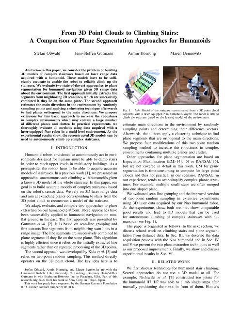
Fig. 1. Left: Model of the staircase reconstructed from a <strong>3D</strong> point cloud<br />
acquired with a laser-equipped Nao humanoid. Right: The robot is able <strong>to</strong><br />
climb the staircase based on the learned model of the environment.<br />
estimate main directions in the environment by randomly<br />
sampling points and determining their difference vec<strong>to</strong>rs.<br />
Afterwards, the authors apply a clustering technique <strong>to</strong> find<br />
plane segments that are orthogonal <strong>to</strong> the main directions.<br />
We propose four modifications of this two-point random<br />
sampling method <strong>to</strong> increase the robustness in complex<br />
environments containing multiple planes and clutter.<br />
Other approaches for plane segmentation are based on<br />
Expectation Maximization (EM) [4], [5] or RANSAC [6],<br />
but are not covered in detail in this work. EM for plane<br />
segmentation is time-consuming <strong>to</strong> compute for large point<br />
clouds and thus not practical in our scenario. RANSAC, in<br />
our experience, tends <strong>to</strong> over-simplify complex planar structures.<br />
For example, multiple small steps are often merged<br />
in<strong>to</strong> one sloped plane.<br />
We evaluated scan-line grouping and the improved version<br />
of two-point random sampling in extensive experiments<br />
using <strong>3D</strong> laser data acquired by our Nao humanoid robot.<br />
As the experiments show, both methods show comparable<br />
good results and lead <strong>to</strong> <strong>3D</strong> models that can be used<br />
for au<strong>to</strong>nomous climbing of complex staircases with humanoids<br />
(see Fig. 1).<br />
The paper is organized as follows. In the next section, we<br />
discuss related work on climbing stairs and plane segmentation<br />
from distance data. In Sec. III, we describe the data<br />
acquisition process with the Nao humanoid and in Sec. IV<br />
and V we present the two plane extraction techniques as well<br />
as our proposed improvements. Finally, we show and discuss<br />
experimental results in Sec. VI.<br />
II. RELATED WORK<br />
We first discuss techniques for humanoid stair climbing.<br />
Several approaches do not use a <strong>3D</strong> model at all. For<br />
example, Nishiwaki et al. [7] constructed <strong>to</strong>e joints for<br />
the humanoid H7. H7 was able <strong>to</strong> climb single steps after<br />
manually positioning the robot in front of them. Honda’s
ASIMO [8] executes a fixed sequence of footsteps that is<br />
locally adapted using data from force sensors.<br />
Michel et al. [9] proposed <strong>to</strong> visually track single objects<br />
that are in the camera’s field of view. This approach is based<br />
on a given <strong>3D</strong> model and a matching between detected and<br />
model edges. After a manual pose initialization, the robot<br />
can determine its pose relative <strong>to</strong> the tracked object, e.g.,<br />
the staircase. Their HRP-2 climbed up staircases with three<br />
steps. Cupec et al. [10] developed a vision-based approach <strong>to</strong><br />
track obstacles. Obstacle detection relies on the assumption<br />
that obstacles and floor are clearly distinguishable in the<br />
images <strong>to</strong> simplify edge detection. The authors presented<br />
experiments in which the robot Johnnie climbed two steps<br />
which were reconstructed in <strong>3D</strong>.<br />
Okada et al. [11] proposed a technique <strong>to</strong> reconstruct<br />
single steps from <strong>3D</strong> stereo data. The authors used a randomized<br />
<strong>3D</strong> Hough transform <strong>to</strong> extract planes. Their humanoid<br />
au<strong>to</strong>nomously climbed a single step. Gutmann et al. [12]<br />
use the efficient scan-line grouping algorithm [2] discussed<br />
in this paper <strong>to</strong> extract models of steps given stereo data.<br />
Using such models, the humanoid QRIO was able <strong>to</strong> climb<br />
up and down staircases consisting of four steps. Chestnutt et<br />
al. [13] applied the two-point random sampling method [3]<br />
also evaluated in this paper <strong>to</strong> identify planes corresponding<br />
<strong>to</strong> steps or flat obstacles based on <strong>3D</strong> laser point cloud<br />
data. To speed-up the process, they restricted the detection<br />
<strong>to</strong> planes ± 30 ◦ from horizontal and used lookup templates<br />
specific <strong>to</strong> the environment when sampling. Their humanoid<br />
robot equipped with a pivoting laser scanner was able <strong>to</strong><br />
climb up and down two successive steps of a small staircase.<br />
Furthermore, there are general approaches for segmentation<br />
of <strong>3D</strong> range data. Hähnel et al. [14] apply a regiongrowing<br />
technique <strong>to</strong> identify planes in <strong>3D</strong> point clouds.<br />
The main focus was here <strong>to</strong> generate compact models<br />
of buildings. EM-based procedures <strong>to</strong> extract planes from<br />
<strong>3D</strong> range data as proposed, for example, by Triebel et<br />
al. [4] and Thrun et al. [5] are rather time-consuming since<br />
the data points need <strong>to</strong> be processed multiple times during<br />
the estimation of the model components and also for the<br />
estimation of the number of components.<br />
Rusu et al. [6] proposed <strong>to</strong> divide the point cloud in<strong>to</strong><br />
different cells and apply RANSAC <strong>to</strong> find polygons locally<br />
which are merged afterwards. The resulting polygonal models<br />
were used for navigation with the ground-based RHex<br />
robot. RANSAC, however, tends <strong>to</strong> over-simplify complex<br />
planar structures in our experience. Multiple small steps are<br />
often merged in<strong>to</strong> one sloped plane which is inappropriate<br />
for safely climbing stairs with a humanoid. Klasing et<br />
al. [15] developed a technique <strong>to</strong> surface segmentation given<br />
a continuous stream of <strong>3D</strong> range data. The authors compute<br />
normal vec<strong>to</strong>rs of points given a local neighborhood and<br />
cluster the points afterwards based on their distance. The<br />
results are quite impressive, however, they highly depend on<br />
the choice of different parameters as stated by the authors.<br />
The recent work of Ben-Tzvi et al. [16] follows a different<br />
approach. The authors first generate a depth image from<br />
the <strong>3D</strong> point cloud and reconstruct con<strong>to</strong>urs of objects.<br />
Afterwards, they segment planes based on the con<strong>to</strong>urs. The<br />
Fig. 2. Left: The two-level environment in which the robot is navigating.<br />
Right: The Nao humanoid is acquiring a <strong>3D</strong> point cloud of the environment<br />
by tilting its head with the 2D laser range finder on <strong>to</strong>p.<br />
technique works well for scenes with a low number of planes,<br />
however, it is unclear how it scales <strong>to</strong> more complex scenes.<br />
III. DATA ACQUISITION<br />
For our experiments, we use a Nao humanoid equipped<br />
with two monocular cameras and a Hokuyo URG-04LX<br />
laser range finder. The sensor is mounted on the <strong>to</strong>p of the<br />
humanoid’s head and provides 2D range data in a field of<br />
view of 240 ◦ at 0.33 ◦ resolution with an update rate of 10 Hz.<br />
With this modified head, Nao is 64 cm tall.<br />
Our robot is navigating in a two-level environment connected<br />
by a spiral staircase with ten steps (see Fig. 2, left). By<br />
tilting its head and combining the 2D scans, the robot obtains<br />
<strong>3D</strong> point cloud data of the environment (see Fig. 2, right).<br />
Note that there is a minimum distance of 50 cm between<br />
the laser plane and the robot’s feet when scanning due <strong>to</strong><br />
the placement of the scanner on the head. Fig. 3 illustrates<br />
an example <strong>3D</strong> scan projected on a manually constructed<br />
CAD model of the staircase. In this case, the robot was<br />
standing close <strong>to</strong> the first step. As can be seen, only the<br />
third step is completely represented in the data. Whereas<br />
the first step and parts of the second one are outside the<br />
robot’s field of view, the higher steps suffer from partial<br />
occlusions. Therefore, in practice the robot has <strong>to</strong> acquire<br />
a new scan every two steps <strong>to</strong> be able <strong>to</strong> build an accurate<br />
model of the staircase. Fig. 4 visualizes the data from the<br />
side. Shown is an orthographic projection of the <strong>3D</strong> scan of<br />
a small staircase with three steps. As can be seen, the data is<br />
highly noisy with errors up <strong>to</strong> 5 cm which makes plane fitting<br />
a challenging task. The noise originates from the inaccuracy<br />
of the laser scanner itself [17] as well as from the estimation<br />
of the sensor’s pose from forward kinematics based on the<br />
joint angles while tilting the head.<br />
IV. SCAN-LINE GROUPING<br />
A fast and efficient method for extracting planes from<br />
a range image is <strong>to</strong> first fit straight line segments <strong>to</strong> each<br />
image row and then perform region growing using the lines<br />
as primitives <strong>to</strong> form planar regions. The approach was<br />
originally presented by Jiang and Bunke [18] and performed<br />
best in a comparison with other earlier range segmentation<br />
techniques [19]. Since then the algorithm has been extended<br />
and improved in order <strong>to</strong> deal with range data containing<br />
varying levels of noise, such as range images obtained from<br />
stereo vision [2]. The method has successfully been applied<br />
on Sony’s QRIO robot, allowing the humanoid <strong>to</strong> recognize
Range Scans<br />
Create Range Image<br />
Fit Line Segments<br />
Find Seed Region<br />
Found?<br />
No<br />
Yes<br />
Region Growing<br />
Fig. 3. Projection of the acquired <strong>3D</strong> point cloud on a manually constructed<br />
<strong>3D</strong> model of the staircase for visualization of the data. During data<br />
acquisition, the robot was standing directly in front of the first step.<br />
0.4<br />
0.3<br />
0.2<br />
0.1<br />
0<br />
0 0.2 0.4 0.6 0.8 1 1.2 1.4<br />
Fig. 4. Side view of <strong>3D</strong> point cloud corresponding <strong>to</strong> a staircase with three<br />
steps, each 7 cm high. As can be seen, the data suffers from noise which<br />
poses challenges on the plane fitting.<br />
floor, stairs, obstacles, and tables, and <strong>to</strong> plan and navigate<br />
its path on an obstacle course [20].<br />
In this work we investigate how well the method is suited<br />
<strong>to</strong> the data taken by Nao’s laser range finder. For this purpose<br />
we slightly extend the method <strong>to</strong> deal with the specific data<br />
acquisition procedure on the Nao humanoid. Fig. 5 shows a<br />
flow chart of the algorithm.<br />
In the first step, the range scans are assembled in<strong>to</strong> a range<br />
image where each pixel holds a <strong>3D</strong> point in a coordinate<br />
system aligned with the image plane. The advantage of such<br />
an image representation is that the con<strong>to</strong>urs of regions can<br />
be found by looking at the <strong>3D</strong> points of neighboring pixels.<br />
As the laser readings are collected by tilting the head of<br />
the robot, a range image can be assembled by sorting the<br />
individual range scans by the pitch angle of the neck joint. In<br />
order <strong>to</strong> obtain more homogeneous data, scans with a similar<br />
pitch angle (difference less than 0.18 ◦ ) 1 are discarded.<br />
Note that the creation of a range image becomes more<br />
involved as the trajec<strong>to</strong>ry of the range finder becomes more<br />
complex, e.g. when also yaw and roll of the head are<br />
changing. In fact, if the robot were <strong>to</strong> walk while collecting<br />
the range scans, a range image representing the full <strong>3D</strong> data<br />
might not exist due <strong>to</strong> the possible occlusion of objects.<br />
In the second step, line segments are fit <strong>to</strong> each range<br />
scan (image row). This is achieved by partitioning the <strong>3D</strong><br />
points in<strong>to</strong> groups where a new group is started whenever<br />
the distance between neighboring points exceeds a threshold<br />
(5 cm). For each group, a straight line is computed by<br />
least squares optimization. Using a run distribution test, the<br />
accuracy of the line is evaluated: if more than a number (15)<br />
of consecutive points all fall on one side of the line, the group<br />
1 Numbers in parentheses indicate the values of parameters used in our<br />
experiments in Sec. VI.<br />
Post Processing<br />
Planar Regions<br />
Fig. 5. Flow-chart of scan-line grouping used in this research. Except<br />
for the initial conversion in<strong>to</strong> a range image, the system is identical <strong>to</strong> the<br />
method on Sony’s QRIO robot [2].<br />
is split at the point most distant <strong>to</strong> the chord connecting start<br />
and end point of the group. The algorithm then processes<br />
each sub-group recursively. Lines with less than a number<br />
of points (5) or shorter than a threshold (5 cm) are discarded.<br />
The extraction of a plane starts by finding three line<br />
segments in neighboring image rows that overlap in their start<br />
and end columns. The three lines must pass a statistical test<br />
before considering them as a seed for a plane: the standard<br />
deviation of the plane fit <strong>to</strong> all points of the three lines (using<br />
least squares) must not be larger than a fac<strong>to</strong>r (2) of the<br />
standard deviation of each line. Once a seed region has been<br />
determined, a region growing procedure is performed that<br />
adds lines in neighboring rows and columns <strong>to</strong> the plane<br />
as long as the standard deviation of the line points with<br />
respect <strong>to</strong> the plane is less than a fac<strong>to</strong>r (2.5) of the standard<br />
deviation of the line itself.<br />
When no more seed regions can be found, the scanline<br />
grouping algorithm terminates. In a post processing<br />
step, the found planes are refined. This includes checking<br />
whether line segments or single data points better fit <strong>to</strong> a<br />
neighboring plane, the merging of co-linear planes, and plane<br />
optimization by discarding border pixels. For a complete<br />
description, we refer <strong>to</strong> the original publication [2].<br />
An interesting property of scan-line grouping is that most<br />
input points are accessed only when fitting line segments.<br />
This makes the algorithm extremely fast as we will see in<br />
our experimental results.<br />
V. TWO-POINT RANDOM SAMPLING<br />
Two-point random sampling as introduced by Kida et<br />
al. [3] relies on the assumption that, in man-made environments,<br />
most surfaces are aligned with respect <strong>to</strong> a<br />
small set of main directions. To exploit this information, the<br />
two-point random sampling algorithm first determines the<br />
main directions of the point cloud by sampling. Then, the<br />
algorithm cuts the data in<strong>to</strong> slices perpendicular <strong>to</strong> each main<br />
direction and searches for plane segments within each slice.<br />
Note that we can not simply assume planes perpendicular <strong>to</strong><br />
the z normal because the scan may be tilted due <strong>to</strong> small<br />
errors in the robot’s pose, and because the front faces of the
steps are also important for the extraction.<br />
A. Basic Algorithm<br />
Given a set of points p 1 ,...,p N , the algorithm extracts<br />
plane segments as follows.<br />
1) Sample a set V of normalized difference vec<strong>to</strong>rs<br />
(|V | = 10000):<br />
V ←<br />
{<br />
p i − p j<br />
∣ pi − p j<br />
∣ ∣<br />
∣ ∣∣∣∣<br />
1 ≤ i, j ≤ N,i ≠ j<br />
The elements of V can be interpreted as points on the<br />
unit sphere. <strong>Point</strong>s p i ,p j originating from different surfaces<br />
in the environment generate randomly distributed<br />
points on the unit sphere. If p i and p j both originate<br />
from a common flat surface in the environment, then<br />
the corresponding point in V is located on the unit<br />
circle with the same normal vec<strong>to</strong>r as the surface.<br />
Hence, all points drawn from surfaces with similar<br />
normal vec<strong>to</strong>rs produce rings with a high point density<br />
on the unit sphere. By considering the point density,<br />
planar surfaces can be distinguished from the noise<br />
occurring in the data.<br />
2) Find a ring-shaped cluster R = {v 1 ,...,v M } ⊆ V .<br />
3) Determine the normal vec<strong>to</strong>r of R by optimizing:<br />
n ← argmax<br />
n<br />
M<br />
∑<br />
k=1<br />
{<br />
1 if n T v k ≈ 0<br />
0 otherwise<br />
4) Cut the point cloud in<strong>to</strong> thin slices perpendicular <strong>to</strong> n.<br />
5) For each slice containing a sufficient number of<br />
points (20): Cluster the points within the slice <strong>to</strong> plane<br />
segments.<br />
Repeat Steps 2) <strong>to</strong> 5) <strong>to</strong> find further planes.<br />
B. Improved Version<br />
While the basic algorithm is sufficient for scenes containing<br />
a moderate number of planes, the robustness has <strong>to</strong> be<br />
improved for more complex scenes containing many planes<br />
or clutter. In this paper, we propose four improvements <strong>to</strong><br />
increase the robustness.<br />
1) During the sampling step, the original algorithm draws<br />
pairs of points randomly from the whole point cloud. In<br />
more complex environments, the probability that both<br />
points originate from the same surface is low, so that<br />
the resulting rings on the unit sphere are not dense<br />
enough <strong>to</strong> be easily distinguishable from the noise in<br />
the data. Additionally, the directions of the difference<br />
vec<strong>to</strong>rs are biased if the dimensions of the environment<br />
are not approximately equal. Drawing the second point<br />
p j from the nearest neighbors of the first point p i with<br />
d 1 ≤ dist(p i ,p j ) ≤ d 2 (d 1 = 2 cm, d 2 = 7 cm) increases<br />
the probability that both points originate from the same<br />
surface and reduces the bias. The lower boundary<br />
reduces the susceptibility <strong>to</strong> noise. Fig. 6 shows the<br />
elements of V as points on the unit sphere. The point<br />
cloud was acquired with a <strong>3D</strong> laser scan in our twolevel<br />
environment depicted in Fig. 2. As can be seen,<br />
when using uniform sampling, the main directions<br />
}<br />
(1)<br />
(2)<br />
Fig. 6. The normalized difference vec<strong>to</strong>rs V from the point cloud in Fig. 3<br />
as points on the unit sphere (black dots). Left: With uniform sampling,<br />
there are no distinct main directions. Right: Using improved sampling<br />
considering neighboring information, the distinct rings corresponding <strong>to</strong> the<br />
main directions can be clearly identified (indicated by their normal vec<strong>to</strong>rs<br />
as red and blue arrows).<br />
cannot be reliably estimated. In contrast, our sampling<br />
strategy that considers neighborhood information leads<br />
<strong>to</strong> clearly distinguishable rings corresponding <strong>to</strong> the<br />
main direction.<br />
2) We combine V-A Step 2) and 3) by applying RANSAC<br />
<strong>to</strong> estimate the main directions. Here, we repeatedly<br />
sample two points in V and determine their normal<br />
vec<strong>to</strong>r <strong>to</strong> find the main directions.<br />
3) In complex environments, the slices that are considered<br />
in V-A Step 5) may contain columns and handrails or<br />
intersect planes that are perpendicular <strong>to</strong> the slice. The<br />
algorithm might mistake these objects for small plane<br />
segments, as they contain a similar number of points.<br />
Therefore, we analyze the eigenvalues λ 1 ≤ λ 2 ≤ λ 3 of<br />
the segmented points’ covariance matrix <strong>to</strong> reject thin<br />
and long plane segments with λ 3 ≫ λ 2 .<br />
4) In a final step, we merge neighboring planes that<br />
probably originated from the same surface. Due <strong>to</strong><br />
measurement noise, the points of a single surface may<br />
fall in<strong>to</strong> two adjacent slices. As only points within one<br />
slice are considered for finding plane segments, these<br />
points generate two distinct, parallel plane segments.<br />
Hence, we identify and merge planes with similar<br />
parameters after the extraction. In particular, planes<br />
are merged if their distance is at most 3 cm and their<br />
normals have an angular difference of at most 11 ◦ .<br />
VI. EXPERIMENTS<br />
We now discuss experimental results obtained with the two<br />
methods presented above given <strong>3D</strong> laser data acquired with<br />
our humanoid robot as described in Sec. III. As discussed<br />
before, the input data contains both random noise and<br />
systematic errors caused by the measurement process. This<br />
noise equally affects the performance of all algorithms.<br />
For our experimental comparison, we use datasets acquired<br />
while the robot was standing at a distance of 70 cm in front of<br />
the staircase, and while standing on the first, third, fifth, and<br />
seventh step. The datasets consist of approximately 132 000<br />
points each.<br />
A. Qualitative Segmentation Results<br />
In our experiments, we found that scan-line grouping as<br />
well as the improved version of the two-point algorithm<br />
reliably extract most plane segments of the staircase within<br />
the robot’s field of view (see Figs. 7-10). Since scan-line
Fig. 7. Result of scan-line grouping on the point cloud of Fig. 3. Each<br />
segmented plane is indicated by a different color. The large blue area<br />
corresponds <strong>to</strong> the floor. <strong>Point</strong>s not belonging <strong>to</strong> a plane are shown in red.<br />
Note how the results degrade as data becomes more sparse at higher steps.<br />
Fig. 8. Segmentation using scan-line grouping on another dataset of the<br />
upper part of our spiral staircase. Several steps are extracted successfully<br />
including their vertical faces. The large green area corresponds <strong>to</strong> the upper<br />
level whereas segments on the right refer <strong>to</strong> a distant wall.<br />
Fig. 9. Result of our improved two-point random sampling method on the<br />
point cloud of Fig. 3. The lower stairs are identified reliably. Parts of the<br />
hand rails are initially merged <strong>to</strong> the front faces, but will be removed later<br />
when reconstructing the staircase model.<br />
grouping can find planes with arbitrary orientations, the<br />
method in general extracts more plane segments than the<br />
two-point algorithm. In most cases, the method also precisely<br />
finds the edges of planes due <strong>to</strong> the refinements carried out<br />
in the post-processing step.<br />
On the other hand, the two-point algorithm is also able<br />
<strong>to</strong> detect smaller plane segments as long as they are aligned<br />
<strong>to</strong> one of the main directions. Only small plane segments<br />
not parallel <strong>to</strong> other planes generate sparse rings on the unit<br />
sphere making such planes hard <strong>to</strong> distinguish from random<br />
noise. Accordingly, the two-point method is less likely <strong>to</strong><br />
extract small planes with less frequent orientations such as<br />
the vertical faces of the rotating part of our spiral staircase.<br />
However, these steps can still be reconstructed from the more<br />
reliable detection of the horizontal faces as shown in Fig. 10.<br />
Note that, for a clearer visualization, Figs. 7-10 show the<br />
convex hulls of the points in the planes.<br />
B. Quantitative Reconstruction Results<br />
We reconstruct stairs in a straightforward manner as briefly<br />
described in the following. First, we intersect horizontal and<br />
vertical planes and obtain a set of straight horizontal lines.<br />
Next, we determine the boundaries of each line segment by<br />
projecting the convex hull of points belonging <strong>to</strong> a plane<br />
on<strong>to</strong> the lines. Finally, the endpoints of parallel lines are<br />
connected <strong>to</strong> form a stair model.<br />
Fig. 10. Segmentation of our improved two-point algorithm on the dataset<br />
of the upper staircase. The same steps as in scan-line grouping are segmented<br />
reliably. Even though some vertical faces are missing, the extraction result<br />
can be used for reconstructing the staircase model.<br />
For the quantitative evaluation, we measured the runtime<br />
and compared the reconstructed dimensions of the steps and<br />
the angles between adjacent faces <strong>to</strong> the ground truth of the<br />
staircase. Table I shows a summary of the results in terms of<br />
average error and standard deviation. The two-point random<br />
sampling algorithm aligns all planes with respect <strong>to</strong> a small<br />
number of common main directions, thus the angular deviation<br />
between parallel planes tends <strong>to</strong> be lower than in models<br />
generated by scan-line grouping. Both methods lead <strong>to</strong> stair<br />
models that are accurate enough <strong>to</strong> be climbed au<strong>to</strong>nomously.<br />
Regarding computational complexity, the scan-line grouping<br />
algorithm is significantly more efficient as it mainly operates<br />
on line segments extracted from the range image, whereas<br />
sampling-based methods operate on the whole point cloud<br />
and need a large number of iterations <strong>to</strong> find all plane<br />
segments with sufficiently high probability.<br />
However, it is worth mentioning that two-point random<br />
sampling can also be used <strong>to</strong> extract plane segments from<br />
accumulated point clouds obtained from multiple viewpoints<br />
whereas scan-line grouping only operates on one range image<br />
from one viewpoint at a time.<br />
C. Stair <strong>Climbing</strong><br />
In order <strong>to</strong> climb complex staircases, we use the reconstructed<br />
<strong>3D</strong> model of the whole staircase. To merge models<br />
resulting from two independent <strong>3D</strong> scans acquired while the
Model Error<br />
(avg ± std)<br />
TABLE I<br />
COMPARISON OF ERROR AND RUNTIME BETWEEN SCAN-LINE<br />
GROUPING AND TWO-POINT RANDOM SAMPLING<br />
Scan-Line Two-<strong>Point</strong><br />
Grouping Random Sampling<br />
Step Height (7 cm) 0.42 ±0.31cm 0.68 ±0.54cm<br />
Step Width (60 cm) 3.40 ±1.95cm 2.25 ±1.97cm<br />
Step Depth (18 cm) 1.17 ±0.67cm 0.90 ±0.61cm<br />
Parallel Planes 2.22 ±2.17° 1.14 ±1.13°<br />
90° Angles 4.97 ±2.13° 3.12 ±1.47°<br />
Runtime 0.025 ±0.001s 3.102 ±1.043s<br />
robot is climbing the stairs, we replace steps with newly<br />
extracted steps that have the same height level. The result of<br />
such a process can be seen in the left image of Fig. 1.<br />
Subsequently, our robot can use the model <strong>to</strong> au<strong>to</strong>nomously<br />
climb up complex staircases. The height of the<br />
stairs <strong>to</strong> step on is thereby given by the model. Since the<br />
motions of humanoids are typically executed inaccurately<br />
and suffer from drift, the robot needs <strong>to</strong> integrate new<br />
observations in order <strong>to</strong> accurately position itself and place<br />
its feet on the individual steps. This is especially important<br />
when climbing the spiral part of the staircase. Otherwise, the<br />
robot might bump in<strong>to</strong> the handrail when not being in the<br />
center of the steps or slip off the stair edge. For this purpose,<br />
our humanoid combines a laser-based localization [21] with<br />
observations from its lower camera that covers the area<br />
directly in front of its feet. Extracted line segments are<br />
matched <strong>to</strong> the edges of the staircase model <strong>to</strong> accurately<br />
determine the robot’s pose on the staircase. Details of this<br />
process are described in our previous work [1]. By using<br />
the reconstructed model of the staircase and local visual<br />
observations in addition, the robot is able <strong>to</strong> reliably climb<br />
the stairs as depicted in Fig. 1. Note that our humanoid<br />
cannot use the laser scanner <strong>to</strong> sense the next step during<br />
stair climbing since there is a minimum distance of 50 cm<br />
between the laser plane and the feet.<br />
VII. CONCLUSIONS AND FUTURE WORK<br />
In this paper, we investigated how a humanoid robot with<br />
<strong>3D</strong> sensing capabilities can perceive staircases in complex<br />
environments and reconstruct a <strong>3D</strong> model accurately enough<br />
in order <strong>to</strong> climb the staircase safely. We compared and<br />
extended two approaches, scan-line grouping and two-point<br />
random sampling. Both techniques lead <strong>to</strong> accurate <strong>3D</strong> models<br />
despite noisy sensor data, a high number of faces, and<br />
clutter in the environment. The learned stair model is slightly<br />
more accurate with two-point random sampling, thus we use<br />
this approach in practice. As we showed in the experiments,<br />
our laser-equipped Nao humanoid is able <strong>to</strong> reliably sense<br />
and climb complex staircases using the methods outlined in<br />
this paper. While we mainly focus on data obtained by tilting<br />
a 2D laser, all methods are general enough <strong>to</strong> be applicable<br />
<strong>to</strong> other <strong>3D</strong> or depth sensors which are currently becoming<br />
more and more available.<br />
REFERENCES<br />
[1] S. Oßwald, A. Görög, A. Hornung, and M. Bennewitz, “Au<strong>to</strong>nomous<br />
climbing of spiral staircases with humanoids,” in Proc. of the<br />
IEEE/RSJ Int. Conf. on Intelligent <strong>Robots</strong> and Systems (IROS), 2011.<br />
[2] J.-S. Gutmann, M. Fukuchi, and M. Fujita, “<strong>3D</strong> perception and<br />
environment map generation for humanoid robot navigation,” The<br />
International Journal of Robotics Research (IJRR), vol. 27, no. 10,<br />
pp. 1117–1134, 2008.<br />
[3] Y. Kida, S. Kagami, T. Nakata, M. Kouchi, and H. Mizoguchi, “Human<br />
finding and body property estimation by using floor segmentation and<br />
<strong>3D</strong> labelling,” in Proc. of the IEEE Int. Conf. on Systems, Man, and<br />
Cybernetics (SMC), 2004.<br />
[4] R. Triebel, W. Burgard, and F. Dellaert, “Using hierarchical EM <strong>to</strong><br />
extract planes from <strong>3D</strong> range scans,” in Proc. of the IEEE Int. Conf. on<br />
Robotics & Au<strong>to</strong>mation (ICRA), 2005.<br />
[5] S. Thrun, C. Martin, Y. Liu, D. Hähnel, R. Emery-Montemerlo,<br />
D. Chakrabarti, and W. Burgard, “A real-time expectation maximization<br />
algorithm for acquiring multi-planar maps of indoor environments<br />
with mobile robots,” IEEE Trans. on Robotics and Au<strong>to</strong>mation, 2003.<br />
[6] R. B. Rusu, A. Sundaresan, B. Morisset, K. Hauser, M. Agrawal,<br />
J.-C. La<strong>to</strong>mbe, and M. Beetz, “Leaving flatland: Efficient real-time<br />
three-dimensional perception and motion planning,” Journal of Field<br />
Robotics, vol. 26, no. 10, pp. 841–862, 2009.<br />
[7] K. Nishiwaki, S. Kagami, Y. Kuniyoshi, M. Inaba, and H. Inoue, “Toe<br />
joints that enhance bipedal and fullbody motion of humanoid robots,”<br />
in Proc. of the IEEE Int. Conf. on Robotics & Au<strong>to</strong>mation (ICRA),<br />
2002.<br />
[8] K. Hirai, M. Hirose, Y. Haikawa, and T. Takenaka, “The development<br />
of Honda humanoid robot,” in Proc. of the IEEE Int. Conf. on Robotics<br />
& Au<strong>to</strong>mation (ICRA), 1998.<br />
[9] P. Michel, J. Chestnutt, S. Kagami, K. Nishiwaki, J. Kuffner, and<br />
T. Kanade, “GPU-accelerated real-time <strong>3D</strong> tracking for humanoid<br />
locomotion and stair climbing,” in Proc. of the IEEE/RSJ Int. Conf. on<br />
Intelligent <strong>Robots</strong> and Systems (IROS), 2007.<br />
[10] R. Cupec, G. Schmidt, and O. Lorch, “Experiments in vision-guided<br />
robot walking in a structured scenario,” in Proc. of the IEEE Int. Symp.<br />
on Industrial Electronics, 2005.<br />
[11] K. Okada, S. Kagami, M. Inaba, and H. Inoue, “Plane segment finder:<br />
Algorithm, implementation and applications,” in Proc. of the IEEE<br />
Int. Conf. on Robotics & Au<strong>to</strong>mation (ICRA), 2001.<br />
[12] J.-S. Gutmann, M. Fukuchi, and M. Fujita, “Stair climbing for<br />
humanoid robots using stereo vision,” in Proc. of the IEEE/RSJ<br />
Int. Conf. on Intelligent <strong>Robots</strong> and Systems (IROS), 2004.<br />
[13] J. Chestnutt, Y. Takaoka, K. Suga, K. Nishiwaki, J. Kuffner, and<br />
S. Kagami, “Biped navigation in rough environments using on-board<br />
sensing,” in Proc. of the IEEE/RSJ Int. Conf. on Intelligent <strong>Robots</strong><br />
and Systems (IROS), 2009.<br />
[14] D. Hähnel, W. Burgard, and S. Thrun, “Learning compact 3d models<br />
of indoor and outdoor environments with a mobile robot,” Robotics &<br />
Au<strong>to</strong>nomous Systems, vol. 44, no. 1, pp. 15–27, 2003.<br />
[15] K. Klasing, D. Wollherr, and M. Buss, “Realtime segmentation of<br />
range data using continuous nearest neighbors,” in Proc. of the IEEE<br />
Int. Conf. on Robotics & Au<strong>to</strong>mation (ICRA), 2009.<br />
[16] P. Ben-Tzvi, S. Charifa, and M. Shick, “Extraction of <strong>3D</strong> images using<br />
pitch-actuated 2D laser range finder for robotic vision,” in Proc. of the<br />
IEEE Int. Workshop on Robotic and Sensors Environments (ROSE),<br />
2010.<br />
[17] L. Kneip, F. Tâche, G. Caprari, and R. Siegwart, “Characterization of<br />
the compact Hokuyo URG-04LX 2D laser range scanner,” in Proc. of<br />
the IEEE Int. Conf. on Robotics & Au<strong>to</strong>mation (ICRA), 2009.<br />
[18] X.-Y. Jiang and H. Bunke, “Fast segmentation of range images in<strong>to</strong><br />
planar regions by scan line grouping,” Machine Vision and Applications,<br />
vol. 7, no. 2, pp. 115 – 122, 1994.<br />
[19] A. Hoover, G. Jean-Baptiste, X. Jiang, P. J. Flynn, H. Bunke, D. B.<br />
Goldgof, K. K. Bowyer, D. W. Eggert, A. W. Fitzgibbon, and R. B.<br />
Fisher, “An experimental comparison of range image segmentation algorithms,”<br />
Transactions on Pattern Analysis and Machine Intelligence,<br />
vol. 18, no. 7, pp. 673 – 689, 1996.<br />
[20] J.-S. Gutmann, M. Fukuchi, and M. Fujita, “Real-time path planning<br />
for humanoid robot navigation,” in Int. Joint Conference on Artificial<br />
Intelligence (IJCAI), Edinburgh, Scotland, 2005.<br />
[21] A. Hornung, K. M. Wurm, and M. Bennewitz, “<strong>Humanoid</strong> robot localization<br />
in complex indoor environments,” in Proc. of the IEEE/RSJ<br />
Int. Conf. on Intelligent <strong>Robots</strong> and Systems (IROS), 2010.