FRAnalyzer Brochure - English - firsttech.ro
FRAnalyzer Brochure - English - firsttech.ro
FRAnalyzer Brochure - English - firsttech.ro

You also want an ePaper? Increase the reach of your titles
YUMPU automatically turns print PDFs into web optimized ePapers that Google loves.
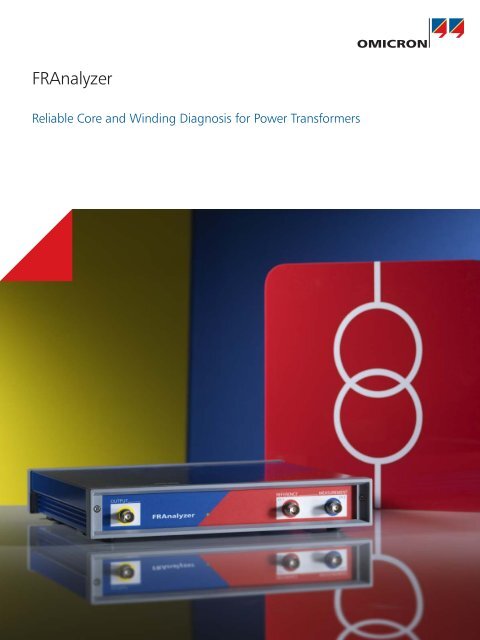
<st<strong>ro</strong>ng>FRAnalyzer</st<strong>ro</strong>ng><br />
Reliable Core and Winding Diagnosis for Power Transformers
Sweep Frequency Response Analysis (SFRA)<br />
The OMICRON <st<strong>ro</strong>ng>FRAnalyzer</st<strong>ro</strong>ng> detects mechanical and electrical changes of the core and winding assembly of power transformers. By<br />
finding winding or core defects after faults, mechanical shocks (e.g. earthquakes) or transportation, it offers a valuable opportunity to<br />
imp<strong>ro</strong>ve the reliability of transformers, to reduce maintenance costs and, most of all, to avoid expensive unexpected outages.<br />
What Is FRA?<br />
Frequency Response Analysis (FRA) is a powerful and<br />
sensitive method to evaluate the mechanical integrity of<br />
core, windings and clamping structures within power<br />
transformers by measuring their electrical transfer<br />
functions over a wide frequency range. OMICRON uses<br />
the SFRA principle (sweep frequency response analysis)<br />
– a worldwide p<strong>ro</strong>ven method for measurements in<br />
frequency domain. The SFRA is a comparative method,<br />
i.e. an evaluation of the transformer condition is done<br />
by comparing an actual set of SFRA results to reference<br />
results. Three methods are commonly used to assess the<br />
measured traces:<br />
5.0<br />
3.0<br />
1.0<br />
-1.0<br />
-3.0<br />
0.2 0.4 0.6 0.8 1 1.2<br />
SWEEP FREQUENCY RESP<br />
Sine generator<br />
Transformer<br />
> > time-based<br />
(current SFRA results will be compared to previous<br />
results of the same unit)<br />
> > type-based<br />
(SFRA of one transformer will be compared to a typeequal<br />
one)<br />
> > phase comparison<br />
(SFRA results of one phase will be compared to the<br />
results of the other phases of the same transformer)<br />
When to Use SFRA?<br />
5.0<br />
Amplitude<br />
variable frequency<br />
complex<br />
RLCM-network<br />
Typical applications of SFRA measurements are:<br />
> > Transformer check after short circuit testing<br />
> > Integrity verification of transformers after transport<br />
> > Condition assessment after the occurrence of high<br />
transient fault currents<br />
> > Routine diagnostic measurement<br />
> > Diagnosis after transformer alarm or p<strong>ro</strong>tection<br />
tripping<br />
> > Testing after significant changes of monitored values<br />
(e.g. combustible gases)<br />
> > Further inspection after the observation of unusual<br />
<strong>ro</strong>utine test results<br />
> > Scientific investigations<br />
The <st<strong>ro</strong>ng>FRAnalyzer</st<strong>ro</strong>ng> injects a sinusoidal excitation<br />
voltage with a continuously increasing frequency<br />
into one end of the transformer winding and<br />
measures the signal returning f<strong>ro</strong>m the other<br />
end. The comparison of input and output<br />
signals generates a unique frequency response<br />
2
Why OMICRON <st<strong>ro</strong>ng>FRAnalyzer</st<strong>ro</strong>ng>?<br />
ONSE ANALYSIS (SFRA)<br />
5.0<br />
3.0<br />
1.0<br />
-1.0<br />
-3.0<br />
0.2 0.4 0.6 0.8 1 1.2<br />
> > Use of the SFRA principle – the industry standard for<br />
measurements in frequency domain<br />
> > Extremely small size and weight using leading edge<br />
technology, for easy handling<br />
> > Highest convenience resulting f<strong>ro</strong>m battery operation<br />
> > Best repeatability due to an innovative connection<br />
technique based on the latest scientific findings<br />
> > Easy-to-use creative software with implemented<br />
standard-based assessment solution<br />
> > World-class OMICRON customer support and valuable<br />
trace assessment help by technology experts<br />
> > Free access to the OMICRON SFRA-User Forum<br />
> > Effective, practice-oriented trainings offered at<br />
OMICRON training centers or on-site at your location<br />
5.0<br />
Phase<br />
which can be compared to reference data.<br />
Deviations indicate geometrical and/or electrical<br />
changes within the transformer. No additional<br />
data p<strong>ro</strong>cessing is required due to a direct<br />
measurement in the frequency domain.<br />
Your Benefits:<br />
> > SFRA is a non-intrusive test method, easy and fast<br />
to perform<br />
> > SFRA also covers low frequencies and thus can<br />
detect core faults, shorted or open turns<br />
> > Direct measurement in frequency domain (as<br />
opposed to the time domain measurement<br />
method) – thus no further mathematical<br />
handling of data is necessary<br />
> > Increasing possibilities for SFRA knowledge<br />
transfer and imp<strong>ro</strong>vement of method th<strong>ro</strong>ugh<br />
g<strong>ro</strong>wing number of users and scientific research<br />
efforts<br />
3
Power Transformer Core & Winding Diagnosis<br />
What P<strong>ro</strong>blems Can Be Detected?<br />
> > The <st<strong>ro</strong>ng>FRAnalyzer</st<strong>ro</strong>ng> can detect p<strong>ro</strong>blems such as: winding<br />
deformation – axial & radial, like hoop buckling, tilting,<br />
spiraling<br />
> > displacements between high and low voltage windings<br />
> > partial winding collapse<br />
> > shorted or open turns<br />
> > faulty g<strong>ro</strong>unding of core or screens<br />
> > core movement<br />
> > b<strong>ro</strong>ken clamping structures<br />
> > p<strong>ro</strong>blematic internal connections<br />
How Does It Work?<br />
Each electrical network has got its unique frequency response.<br />
Therefore it is usually called a fingerprint. Geometrical changes<br />
within and between the elements of the network cause<br />
deviations of its frequency response.<br />
Differences between an SFRA fingerprint and the result of an<br />
actual measurement are an indication of positional or electrical<br />
variations of the internal components. Different failures are<br />
directly related to different sections of the frequency range and<br />
can usually be discerned f<strong>ro</strong>m each other.<br />
Deformed core<br />
Collapsed tap winding<br />
Damaged main winding<br />
Displaced internal connections<br />
4
windings<br />
core<br />
C<br />
C<br />
R<br />
L<br />
R<br />
L<br />
C<br />
L<br />
R<br />
C<br />
C<br />
L R<br />
C<br />
C<br />
C<br />
C<br />
C<br />
C<br />
C<br />
tank<br />
wall<br />
The core-and-winding-assembly of power transformers<br />
can be seen as a complex electrical network of<br />
capacitances, inductances and resistors.<br />
Your Benefits:<br />
> > High reliability of test results due to the applied<br />
measurement method and high repeatability<br />
of test results due to sophisticated connection<br />
technique<br />
> > SFRA can detect winding and core p<strong>ro</strong>blems<br />
which remain hidden using any other diagnostic<br />
method<br />
> > Valuable and cost-effective tool for deciding<br />
whether a transformer can be powered up again<br />
after p<strong>ro</strong>tection tripping or not<br />
> > Informative failure analysis helps avoid expensive<br />
defueling of transformer's active part<br />
5
Unique Connection Technique<br />
The OMICRON <st<strong>ro</strong>ng>FRAnalyzer</st<strong>ro</strong>ng> uses an innovative connection technique to enable exceptional repeatability of the test results.<br />
Exceptional Repeatability with Advanced<br />
Connection Technique<br />
Since SFRA is a comparative method, it is of vital<br />
importance that measurements on the same object under<br />
the same conditions p<strong>ro</strong>duce identical results regardless<br />
of the external noise level.<br />
Only a very high degree of repeatability can ensure that<br />
even small deviations of compared SFRA-traces are related<br />
to changes within the observed transformer and not to<br />
inaccuracies within the measurement setup.<br />
According to the standard of knowledge, the connections<br />
between the measuring device and the transformer<br />
terminals, as well as the g<strong>ro</strong>unding technique, have a key<br />
influence on rep<strong>ro</strong>ducibility.<br />
Unique Connection Technique<br />
In close cooperation with leading Universities in the field<br />
of FRA testing on power transformers, OMICRON has<br />
developed a sophisticated connection solution to achieve<br />
highest possible repeatability of the results.<br />
Specially designed screw-type-connection clamps<br />
p<strong>ro</strong>vide reliable electrical contact to the transformer. The<br />
<st<strong>ro</strong>ng>FRAnalyzer</st<strong>ro</strong>ng> uses double shield coax cables (RG223U) to<br />
ensure the highest available signal-to-noise-ratio (SNR).<br />
6
To enable the g<strong>ro</strong>unding of the coaxial cable shields at the<br />
transformer housing, which is the reference potential, an<br />
additional connection f<strong>ro</strong>m the terminal adapter to the<br />
transformer tank is required.<br />
A poor g<strong>ro</strong>unding technique can lead to unrep<strong>ro</strong>ducible<br />
and therefore unusable SFRA results. In order to achieve<br />
the best possible SFRA measurements, the g<strong>ro</strong>unding<br />
connections should be of lowest inductance and p<strong>ro</strong>vide<br />
a large surface area.<br />
Therefore the use of braids, which are less sensitive to<br />
interferences and make the measurement independent<br />
f<strong>ro</strong>m the cable positioning is st<strong>ro</strong>ngly recommended.<br />
The Double-Braid Concept<br />
OMICRON p<strong>ro</strong>vides a double-braid solution which forms a<br />
shield a<strong>ro</strong>und the bushing arranged in a defined position.<br />
In order to achieve a high degree of repeatability, the<br />
extension leads should run tightly along the body of the<br />
bushings. This is ensured by screw clamps which connect<br />
the braids always with ideal length to the base of the<br />
bushing.<br />
Due to their high flexibility the tester can lay the braids<br />
tightly to the bushing. This clamp-and-braid arrangement<br />
complies with the strict demands of engineers a<strong>ro</strong>und<br />
the globe requiring a "g<strong>ro</strong>und extension as short as<br />
possible and with the smallest achievable loop" – only the<br />
<st<strong>ro</strong>ng>FRAnalyzer</st<strong>ro</strong>ng> p<strong>ro</strong>vides this in such an exceptional manner.<br />
Your Benefits:<br />
> > True-value results due to accurate rep<strong>ro</strong>ducibility<br />
> > High-end clamps for exceptional repeatability<br />
> > Minimal noise interference due to the use of<br />
two b<strong>ro</strong>ad g<strong>ro</strong>und braids<br />
> > Time saving because of cutting functionality of<br />
screw-type clamps<br />
7
Fast, Easy and Efficient Software<br />
The <st<strong>ro</strong>ng>FRAnalyzer</st<strong>ro</strong>ng> software is specially designed to fit the needs of the on-site testing personnel as well as the requirements<br />
of the engineers analyzing the data. The tests are easy to establish and fast to perform. The software suggests useful test<br />
sequences according to transformer type and vector g<strong>ro</strong>up. An implemented assessment algorithm gives the user a powerful<br />
tool for a fast analysis of the results. The auto-report functionality generates a complete report within seconds.<br />
Getting Started<br />
Usually the test sequence starts with the establishment of<br />
the transformer to be tested. The nameplate data will be<br />
stored with all measured data. The terminal markings can<br />
be chosen f<strong>ro</strong>m different templates such as IEC or ANSI.<br />
If there is older data of the same transformer (fingerprint)<br />
available in the database, this test can be used as a<br />
template.<br />
Based on transformer type and vector g<strong>ro</strong>up, a test<br />
sequence is suggested. Other sequences can also<br />
be added and changed freely and individually. The<br />
new Connection Scheme (shown in the upper right<br />
screenshot) is an ideal, easy-to-use graphical support<br />
for unexperienced users for a p<strong>ro</strong>per assignment of the<br />
connections. The preview pane gives a quick overview<br />
of curves.<br />
Sweep Settings<br />
Your<br />
Company<br />
Header<br />
Any test with the <st<strong>ro</strong>ng>FRAnalyzer</st<strong>ro</strong>ng> is performed with a sweep<br />
settings p<strong>ro</strong>file. These p<strong>ro</strong>files are fully customizable and<br />
can be set for any test individually. In contrast to other<br />
instruments, the spacing of the <st<strong>ro</strong>ng>FRAnalyzer</st<strong>ro</strong>ng> measurement<br />
points (sweep mode) can be logarithmic or linear, there<br />
can also be generated as many frequency sub-ranges<br />
as needed. In addition to the number of points, the<br />
receiver bandwidth can be adjusted to achieve an optimal<br />
signal-to-noise ratio (SNR).<br />
With one look, the user can get an overview of the<br />
magnitude (gain) and phase angle of the transformer's<br />
transfer function. It is possible to g<strong>ro</strong>up the shown traces,<br />
e.g. just HV measurements, or just the results of the<br />
tertiary winding. Cursors are available as well as an easy<br />
to use zoom functionality. A copy-to-clipboard function<br />
allows a fast insertion of full or zoomed trace pictures<br />
into office documents, etc. Despite the predefined sweep<br />
mode, the traces can be displayed in linear or logarithmic<br />
scaling to observe every part of the trace in a useful way.<br />
8
The Reference Principle<br />
After the measurement a reference test can be defined.<br />
This can be a fingerprint of the same transformer or<br />
measured data of various sister transformers. Of course<br />
it is also possible to compare the traces measured on<br />
different phases of a transformer without setting a<br />
reference test.<br />
Implemented Assessment Tool<br />
The <st<strong>ro</strong>ng>FRAnalyzer</st<strong>ro</strong>ng> p<strong>ro</strong>vides the user a mathematical solution<br />
for a comparison of the traces based on the standard<br />
DL 911/2004.<br />
Scientific investigations and experience have p<strong>ro</strong>ven<br />
this method to be reliable and sensitive. Therefore the<br />
implemented algorithm p<strong>ro</strong>vides a powerful tool for a fast<br />
assessment of the test data.<br />
Assessment tool confirms healthy winding status<br />
Data Storage, Export/Import<br />
All measured data is stored within a supplied database.<br />
This ensures a time-effective data handling and avoids<br />
the p<strong>ro</strong>blems typically arising with file storage systems<br />
for a large number of tests. These stored data can easily<br />
be arranged and sorted by several parameters. An easyto-handle<br />
export function enables the user to store the<br />
data additionally in different formats such as CIGRE<br />
Exchange Format (.xfra) or .csv (which can be imported<br />
into MS Excel). The <st<strong>ro</strong>ng>FRAnalyzer</st<strong>ro</strong>ng> software also allows<br />
the import of other manufacturers data in their specific<br />
formats such as Doble, FRAMIT, FRAX, etc.<br />
The Auto-Report Function<br />
The <st<strong>ro</strong>ng>FRAnalyzer</st<strong>ro</strong>ng> software automatically generates a test<br />
report within seconds. It can be printed out or stored<br />
in .pdf format or MS Excel. It contains all information<br />
about the transformer, the test, all traces and assessment<br />
results.<br />
Failure clearly identified by the assessment tool<br />
Your Benefits:<br />
> > Fast, easy, efficient handling th<strong>ro</strong>ugh the<br />
user interface<br />
> > High flexibility due to freely selectable<br />
sweep‐settings<br />
> > Cost saving due to included database solution<br />
> > Included assessment tool saves money<br />
otherwise spent on expert analyses<br />
> > Easy localization to global market via different<br />
language packages<br />
> > Effective work due to the fast auto-reporting<br />
> > Helpful connection schemes support the<br />
unexperienced user to make the right<br />
connections<br />
> > Easy to use comparison of multiple tests<br />
> > Increased import and export functionality<br />
9
The 'one box' Solution<br />
The complete <st<strong>ro</strong>ng>FRAnalyzer</st<strong>ro</strong>ng> package comes in a firm arrangement – every component has its place. The complete package<br />
is designed for field use and has successfully passed vibration-, shock- and climatic resistance tests by an independent<br />
and accredited test laboratory.<br />
Technical Data<br />
General<br />
Envi<strong>ro</strong>nmental<br />
Frequency range<br />
Meas. point spacing<br />
Calibration interval<br />
10 Hz to 20 MHz (selectable)<br />
logarithmic, linear, or both<br />
every 3 years<br />
Operating ambient<br />
temperature<br />
Operating relative<br />
humidity<br />
-10...+55 ºC / +14...+131 ºF<br />
20... 95 %, non-condensing<br />
Source Output<br />
FRA method<br />
Output impedance<br />
Connector<br />
Amplitude<br />
Number of meas. points<br />
Sweep frequency<br />
50 W<br />
BNC (double shielded)<br />
2.83 V p-p = 1 Vrms at 50 W load<br />
max. 3,201 (user-selectable)<br />
Mechanical data / supply voltage<br />
Weight<br />
< 2 kg without measuring cables<br />
Dimensions<br />
26 x 5 x 26.5 cm / 10.25 x 2 x 10.5 in<br />
(W x H x D)<br />
DC power supply DC 10 V to 24 V / 10 W<br />
AC power supply AC 100 V to 240 V / 50 to 60 Hz<br />
Inputs (Reference – CH 1, Measurement – CH 2)<br />
Impedance<br />
low 50 W, or high impedance 1 MW<br />
(selectable)<br />
Connector<br />
BNC (double shielded)<br />
Dynamic range > 120 dB<br />
Accuracy<br />
< 0,1 dB (down to -50 dB) and<br />
±1 dB (between -50 dB and -80 dB)<br />
PC requirements (minimum)<br />
Interface USB 1.1<br />
PC operating system Windows 2000, Windows XP,<br />
Windows Vista 32bit or<br />
Windows 7 32bit/64bit<br />
P<strong>ro</strong>cessor<br />
Pentium 1 GHz<br />
Memory<br />
1 GB RAM<br />
Drive<br />
CD-ROM<br />
PC Software 'OMICRON <st<strong>ro</strong>ng>FRAnalyzer</st<strong>ro</strong>ng>' for<br />
> > Operation of the <st<strong>ro</strong>ng>FRAnalyzer</st<strong>ro</strong>ng><br />
> > Measurements with test templates<br />
> > Advanced visualization and analysis of test results<br />
> > Assessment of the measuring results<br />
> > Database handling<br />
> > Reporting<br />
10
Ordering Information<br />
VE000660<br />
<st<strong>ro</strong>ng>FRAnalyzer</st<strong>ro</strong>ng> complete set<br />
The set consists of the following accessories (can also be ordered separately; one piece per order no):<br />
Order No. Qty. Description<br />
VEHK0660 1 Coaxial-Cable Red with Cable Drum (18 m / 59 ft)<br />
VEHK0661 1 Coaxial-Cable Blue with Cable Drum (18 m / 59 ft)<br />
VEHK0662 1 Coaxial-Cable Yellow with Cable Drum (18 m / 59 ft)<br />
VEHZ0661 4 Aluminum Braid Rolls (5 m / 16 ft)<br />
VEHK0615 1 G<strong>ro</strong>unding Cable 6 mm² gn/ye (6 m / 20 ft)<br />
VEHZ0662 4 Screw-Clamps for Aluminum Braid<br />
VEHZ0664 2 Bushing-Clamps<br />
VEHZ0667 1 BNC Adapter Set<br />
VESD0662 1 User Manual<br />
VEHZ0659 1 Power Supply and Battery Charger<br />
VEHZ0657 1 Crank Handle<br />
- 1 <st<strong>ro</strong>ng>FRAnalyzer</st<strong>ro</strong>ng> Software<br />
Additional Accessory for <st<strong>ro</strong>ng>FRAnalyzer</st<strong>ro</strong>ng>:<br />
VEHZ0673 Clamps Set for Short Bushings<br />
(consisting of 2 short aluminum braids (1.5 m / 5 ft), 2 clamps and 1 carry bag)<br />
VESM0661 <st<strong>ro</strong>ng>FRAnalyzer</st<strong>ro</strong>ng> Software Upgrade to 2.0<br />
(for users of older software versions than 2.0)<br />
11
OMICRON is an international company serving the electrical<br />
power industry with innovative testing and diagnostic solutions.<br />
The application of OMICRON p<strong>ro</strong>ducts allows users to assess<br />
the condition of the primary and secondary equipment on their<br />
systems with complete confidence. Services offered in the area of<br />
consulting, commissioning, testing, diagnosis, and training make<br />
the p<strong>ro</strong>duct range complete.<br />
Customers in more than 140 countries rely on the company’s<br />
ability to supply leading edge technology of excellent quality.<br />
B<strong>ro</strong>ad application knowledge and extraordinary customer support<br />
p<strong>ro</strong>vided by offices in North America, Eu<strong>ro</strong>pe, South and East Asia,<br />
Australia, and the Middle East, together with a worldwide network<br />
of distributors and representatives, make the company a market<br />
leader in its sector.<br />
For a complete list of available literature please visit our website.<br />
Americas<br />
OMICRON elect<strong>ro</strong>nics Corp. USA<br />
12 Greenway Plaza, Suite 1510<br />
Houston, TX 77046, USA<br />
Phone: +1 713 830-4660<br />
+1 800-OMICRON<br />
Fax: +1 713 830-4661<br />
info@omic<strong>ro</strong>nusa.com<br />
Asia-Pacific<br />
OMICRON elect<strong>ro</strong>nics Asia Limited<br />
Suite 2006, 20/F, Tower 2<br />
The Gateway, Harbour City<br />
Kowloon, Hong Kong S.A.R.<br />
Phone: +852 3767 5500<br />
Fax: +852 3767 5400<br />
info@asia.omic<strong>ro</strong>n.at<br />
Eu<strong>ro</strong>pe, Middle East, Africa<br />
OMICRON elect<strong>ro</strong>nics GmbH<br />
Oberes Ried 1<br />
6833 Klaus, Austria<br />
Phone: +43 5523 507-0<br />
Fax: +43 5523 507-999<br />
info@omic<strong>ro</strong>n.at<br />
© OMICRON L179, May 2011<br />
Subject to change without notice<br />
www.omic<strong>ro</strong>n.at • www.omic<strong>ro</strong>nusa.com