CMK-02 volume corrector - firsttech.ro
CMK-02 volume corrector - firsttech.ro
CMK-02 volume corrector - firsttech.ro

You also want an ePaper? Increase the reach of your titles
YUMPU automatically turns print PDFs into web optimized ePapers that Google loves.
][][<br />
<st<strong>ro</strong>ng>CMK</st<strong>ro</strong>ng>-<st<strong>ro</strong>ng>02</st<strong>ro</strong>ng> <st<strong>ro</strong>ng>volume</st<strong>ro</strong>ng> <st<strong>ro</strong>ng>corrector</st<strong>ro</strong>ng><br />
OPERATING AND MAINTENANCE MANUAL<br />
<st<strong>ro</strong>ng>CMK</st<strong>ro</strong>ng>2/005U/KJ<br />
Łódź, July 2006 r.<br />
Notice:<br />
COMMON S.A .reserves the right of modification of the devices with keeping the fulfillment of<br />
app<strong>ro</strong>priate requirements concerning the accuracy and the safety.
Contents<br />
1. INTRODUCTION ...................................................................................................................................................4<br />
2. CONSTRUCTION ..................................................................................................................................................5<br />
3. MAIN TECHNICAL AND METROLOGICAL DATA ......................................................................................6<br />
3.1. BASIC DATA OF THE MICROPROCESSOR SYSTEM. ................................................................................................6<br />
3.2. CONDITIONS FOR USE OF THE <st<strong>ro</strong>ng>CMK</st<strong>ro</strong>ng>-<st<strong>ro</strong>ng>02</st<strong>ro</strong>ng> VOLUME CORRECTOR. ...........................................................................6<br />
3.3. BASIC METROLOGICAL DATA..............................................................................................................................6<br />
4. ASSEMBLY AND INSTALLATION....................................................................................................................7<br />
4.1. CONNECTING THE CORRECTOR ...........................................................................................................................7<br />
4.2. MECHANICAL ASSEMBLY....................................................................................................................................9<br />
4.3. PARAMETERS OF USE ........................................................................................................................................16<br />
5. OPERATING THE CORRECTOR.....................................................................................................................17<br />
5.1. MAIN MENU......................................................................................................................................................18<br />
5.2. ALGORITHM CONSTANTS ..................................................................................................................................18<br />
5.3. CURRENT DATA ................................................................................................................................................19<br />
5.5. GAS COMPOSITION............................................................................................................................................24<br />
5.6. SERIAL CONNECTIONS.......................................................................................................................................25<br />
5.7. CONFIGURATION...............................................................................................................................................25<br />
5.8. NAMEPLATE .....................................................................................................................................................25<br />
5.9. CLOCK..............................................................................................................................................................26<br />
6.1. CONFIGURATION OF THE CORRECTOR OPERATING PARAMETERS ......................................................................28<br />
6.2. PROGRAMMING THE ALGORITHM CONSTANTS ..................................................................................................30<br />
6.3. MODIFICATION OF PARAMETER VALUE.............................................................................................................31<br />
6.4. SETTING THE OPERATING PARAMETERS. ...........................................................................................................31<br />
6.5. CONFIGURATION ACTIVATION ..........................................................................................................................48<br />
7. COMMUNICATION OF THE CORRECTOR WITH A COMPUTER. ........................................................50<br />
8. PACKING, STORAGE AND TRANSPORTATION.........................................................................................51<br />
9. TABLE OF AVAILABLE PARAMETERS .......................................................................................................52<br />
10. TABLE OF ALARMS.........................................................................................................................................56<br />
<st<strong>ro</strong>ng>CMK</st<strong>ro</strong>ng>-<st<strong>ro</strong>ng>02</st<strong>ro</strong>ng> Operating and maintenance manual 3
1. Int<strong>ro</strong>duction<br />
The <st<strong>ro</strong>ng>CMK</st<strong>ro</strong>ng>-<st<strong>ro</strong>ng>02</st<strong>ro</strong>ng> <st<strong>ro</strong>ng>volume</st<strong>ro</strong>ng> <st<strong>ro</strong>ng>corrector</st<strong>ro</strong>ng> is used for determination of the <st<strong>ro</strong>ng>volume</st<strong>ro</strong>ng> and the gas flow in<br />
standard conditions. It is designed for installation in the reduction and the gas measuring<br />
stations. On the base of pulses generated by the reed contact sensor, placed in the gas meter,<br />
the <st<strong>ro</strong>ng>corrector</st<strong>ro</strong>ng> counts the uncorrected gas <st<strong>ro</strong>ng>volume</st<strong>ro</strong>ng>. At the same time the temperature and the gas<br />
pressure measurement is taken. On the base of the taken measurements and the declared gas<br />
composition the <st<strong>ro</strong>ng>corrector</st<strong>ro</strong>ng> calculates the compressibility coefficient, using the permissible<br />
method (in gas industry GERG 88), and converts the uncorrected gas <st<strong>ro</strong>ng>volume</st<strong>ro</strong>ng> to standard<br />
conditions (in Poland: p=101,325 kPa; T=273,15 K).<br />
The <st<strong>ro</strong>ng>corrector</st<strong>ro</strong>ng> also calculates and logs:<br />
• correction coefficient,<br />
• real <st<strong>ro</strong>ng>volume</st<strong>ro</strong>ng> flow,<br />
• standard <st<strong>ro</strong>ng>volume</st<strong>ro</strong>ng> flow,<br />
• gas density in standard conditions,<br />
• energy and mass flow flowing th<strong>ro</strong>ugh the pipeline,<br />
• date, time and maximum number of pulses counted in one minute,<br />
• date, time and hourly peak values between completed hours ,<br />
• date, time and hourly peak values with sliding window.<br />
These data together with the temperature and the gas pressure and uncorrected and<br />
standard <st<strong>ro</strong>ng>volume</st<strong>ro</strong>ng> are stored in nonvolatile <st<strong>ro</strong>ng>corrector</st<strong>ro</strong>ng>’s memory. They can be read on the fourline,<br />
twenty-character liquid crystal display or remotely via the serial transmission connections.<br />
The <st<strong>ro</strong>ng>corrector</st<strong>ro</strong>ng> is p<strong>ro</strong>vided with the transmission p<strong>ro</strong>tocol compliant with the GAZ-MODEM<br />
p<strong>ro</strong>tocol as well as with the functional subset of MODBUS p<strong>ro</strong>tocol (RTU and ASCII version).<br />
Each signal converter operating in theRS-GAZ2 standard can cooperate with the system. Its<br />
application is especially recommended for:<br />
• continuous reading: two-channel signal converter with the CZAK-<st<strong>ro</strong>ng>02</st<strong>ro</strong>ng> power supply or the<br />
CBS-<st<strong>ro</strong>ng>02</st<strong>ro</strong>ng> signalling barrier. These devices require the power supply connection.<br />
• periodical reading: the CAK-<st<strong>ro</strong>ng>02</st<strong>ro</strong>ng> battery converter or the COG-<st<strong>ro</strong>ng>02</st<strong>ro</strong>ng> optical connection.<br />
These devises do not require the power supply connection.<br />
The <st<strong>ro</strong>ng>corrector</st<strong>ro</strong>ng> is manufactured in two versions, depending on the way of supply of additional<br />
PC-70 pressure converter:<br />
1. In standard version – it is possible connection of one or two additional PC-70<br />
converters supplied via the external converter (i.e. the CZAK-<st<strong>ro</strong>ng>02</st<strong>ro</strong>ng> converter, the CBS-<st<strong>ro</strong>ng>02</st<strong>ro</strong>ng><br />
barrier).<br />
2. In version „B” (on special order) – it enables connection of one PC-70 pressure<br />
converter supplied f<strong>ro</strong>m the <st<strong>ro</strong>ng>corrector</st<strong>ro</strong>ng>’s internal battery (without necessity to connect the<br />
additional power supply). In this version after the factory number the „B” character is<br />
added. The <st<strong>ro</strong>ng>corrector</st<strong>ro</strong>ng> in the „B” version is equipped with two inputs and one digital<br />
output.<br />
<st<strong>ro</strong>ng>CMK</st<strong>ro</strong>ng>-<st<strong>ro</strong>ng>02</st<strong>ro</strong>ng> Operating and maintenance manual 4
2. Construction<br />
The <st<strong>ro</strong>ng>CMK</st<strong>ro</strong>ng>-<st<strong>ro</strong>ng>02</st<strong>ro</strong>ng> <st<strong>ro</strong>ng>corrector</st<strong>ro</strong>ng> has two-chamber construction. In the upper chamber it is located the<br />
mainboard with the p<strong>ro</strong>cessor, serial connection systems and measuring converters used for<br />
conversion of signals f<strong>ro</strong>m the measuring converters to digital signals. The absolute pressure<br />
sensor is also located there. The chamber is sealed by the manufacturer; tearing off the seal<br />
is equivalent to warranty loss and annulment of factory certificate!<br />
The lower chamber includes the terminal strip to which the data transmission circuits and<br />
the signalling and measuring circuits are connected. The batteries and the configuration<br />
selector switch used when manually configuring the <st<strong>ro</strong>ng>corrector</st<strong>ro</strong>ng>’s operating parameters<br />
(discussed below) are also located there. This chamber should be sealed by the user (see the<br />
chapter „Assembly and installation”).<br />
Data transmission f<strong>ro</strong>m the <st<strong>ro</strong>ng>corrector</st<strong>ro</strong>ng> may be performed with the use of RS-GAZ2/RS-232<br />
signal converter eg: CZAK-<st<strong>ro</strong>ng>02</st<strong>ro</strong>ng>, CAK-<st<strong>ro</strong>ng>02</st<strong>ro</strong>ng>, CBS-<st<strong>ro</strong>ng>02</st<strong>ro</strong>ng> and via the OPTO-GAZ connection (COG-<st<strong>ro</strong>ng>02</st<strong>ro</strong>ng><br />
interface). After putting the OPTO-GAZ head against the <st<strong>ro</strong>ng>corrector</st<strong>ro</strong>ng>’s f<strong>ro</strong>nt plate at the marked<br />
place, it is carried out the automatic switching over the COM1 line f<strong>ro</strong>m the RS1 permanent<br />
connection (connected to the terminal strip or to the TUCHEL socket). This enables direct<br />
reading of the <st<strong>ro</strong>ng>corrector</st<strong>ro</strong>ng> without necessity to disconnect the remaining RS1 and RS2<br />
connections (in case when both are used). You can buy the COG-<st<strong>ro</strong>ng>02</st<strong>ro</strong>ng> interface in COMMON<br />
S.A.<br />
Operating conditions of the <st<strong>ro</strong>ng>CMK</st<strong>ro</strong>ng>-<st<strong>ro</strong>ng>02</st<strong>ro</strong>ng> <st<strong>ro</strong>ng>corrector</st<strong>ro</strong>ng> are included in chapters „Basic<br />
technical and met<strong>ro</strong>logical data” and „Assembly and installation”. We recommend<br />
detailed acquainting with these chapters prior to assembly of the device.<br />
The <st<strong>ro</strong>ng>CMK</st<strong>ro</strong>ng>-<st<strong>ro</strong>ng>02</st<strong>ro</strong>ng> <st<strong>ro</strong>ng>corrector</st<strong>ro</strong>ng> can operate in two basic configurations:<br />
a) Battery operation – the <st<strong>ro</strong>ng>corrector</st<strong>ro</strong>ng> operates in accounting mode with possibility of<br />
connecting two inputs and two pulse outputs with the p<strong>ro</strong>grammable function (standard<br />
version); possibility of reading data after connecting the external signal converter of<br />
app<strong>ro</strong>ved type; calculation of the Qn flow is performed on the base of low frequency<br />
pulses LF.<br />
b) Mains operation (with external supply) – all functions as in the battery operation and<br />
additional possibility of connecting the high frequency pulse transmitter HF of app<strong>ro</strong>ved<br />
type and possibility of connecting two additional PC-70 pressure converters.<br />
The <st<strong>ro</strong>ng>CMK</st<strong>ro</strong>ng>-<st<strong>ro</strong>ng>02</st<strong>ro</strong>ng> <st<strong>ro</strong>ng>corrector</st<strong>ro</strong>ng> has the possibility of logging up to 32768 samples of accounting<br />
data, that ensures permanent logging the device’s operation for 142 days with the set 10<br />
minute logging interval. The daily data memory ensures permanent logging for 5 years, the<br />
monthly data memory – for the whole period of the <st<strong>ro</strong>ng>corrector</st<strong>ro</strong>ng> operation, the list of events<br />
may contain up to 4000 logs.<br />
With the assumption of 2 hour daily operation without the external power supply with the<br />
LCD display switched on, the battery supply system ensures the 5 year permanent operation of<br />
the <st<strong>ro</strong>ng>corrector</st<strong>ro</strong>ng>.<br />
<st<strong>ro</strong>ng>CMK</st<strong>ro</strong>ng>-<st<strong>ro</strong>ng>02</st<strong>ro</strong>ng> Operating and maintenance manual 5
3. Main technical and met<strong>ro</strong>logical data<br />
3.1. Basic data of the mic<strong>ro</strong>p<strong>ro</strong>cessor system.<br />
- P<strong>ro</strong>cessor: INTEL 386<br />
- Memory: 256kB – Static RAM, 2MB or 4MB – FLASH ROM,<br />
- A/C converter: 24-bit sigma-delta<br />
- Clock: Internal real time clock RTC<br />
- Communication: Two independent serial transmission channels<br />
RS-GAZ2 (up to 115200 baud)<br />
- Display: LCD – four lines, twenty characters each; maintaining<br />
contract in the whole range of ambient temperatures (-<br />
25 O C ÷ +55 O C)<br />
- Keyboard: foil keyboard, four keys<br />
- Technology: 2,7-Volt<br />
- Power supply: 2 lithium batteries SL-780 3,6V/13,5Ah (p<strong>ro</strong>tected by<br />
resistors and insulating sleeve)<br />
3.2. Conditions for use of the <st<strong>ro</strong>ng>CMK</st<strong>ro</strong>ng>-<st<strong>ro</strong>ng>02</st<strong>ro</strong>ng> <st<strong>ro</strong>ng>volume</st<strong>ro</strong>ng> <st<strong>ro</strong>ng>corrector</st<strong>ro</strong>ng>.<br />
- Ambient temperature: -25 O C ÷ +55 O C<br />
- Relative humidity: max. 95% at 55 O C<br />
- Casing degree of p<strong>ro</strong>tection: IP54<br />
- EMI disturbances: character and disturbances level fulfils the requirements<br />
of company standard PGNiG ZN-G-4007 z 2001r.<br />
- Marking of the explosion p<strong>ro</strong>of casing: II 2G EEx ia IIB T3<br />
- Certificate number: KDB 1453 04 ATEX 220<br />
- Compliance with standards: PN-EN 50014 , PN-EN 50<st<strong>ro</strong>ng>02</st<strong>ro</strong>ng>0<br />
3.3. Basic met<strong>ro</strong>logical data<br />
Pressure measurement:<br />
For the measurement it is used the absolute pressure sensor operating in one of the<br />
following measuring ranges:<br />
0,09÷0,7 MPa, 0,25÷2 MPa, 0,5÷4 MPa, 1÷8 MPa , 1,3÷10 MPa.<br />
The limiting relative er<strong>ro</strong>r of pressure measurement related to the measured value amounts to<br />
δ=0,3% in the whole range of the operating pressure and temperature. The pressure measuring<br />
range is p<strong>ro</strong>grammable within the sensor measuring range. The pressure sensor is mounted<br />
inside the <st<strong>ro</strong>ng>CMK</st<strong>ro</strong>ng>-<st<strong>ro</strong>ng>02</st<strong>ro</strong>ng> <st<strong>ro</strong>ng>corrector</st<strong>ro</strong>ng>’s casing.<br />
Temperature measurement:<br />
The gas temperature measurement is performed by the PT1000 class A sensor with the<br />
measuring range -25 O C ÷ +50 O C. The limiting relative er<strong>ro</strong>r of the measurement related to the<br />
measured value (in Kelvin scale) amounts to δ=0,2% in the whole range of ambient<br />
temperature. The temperature measuring range is p<strong>ro</strong>grammable within the PT1000 sensor<br />
measuring range. The sensor is fixed in the measuring section or in the gas meter.<br />
NOTICE:<br />
The P and T er<strong>ro</strong>r values are compliant with OIML SP6 Sr9 recommendations on the<br />
subject: „Elect<strong>ro</strong>nic instruments for <st<strong>ro</strong>ng>volume</st<strong>ro</strong>ng>tric gas meters” and with the company standard<br />
PGNiG ZN-G-40001 f<strong>ro</strong>m 2001r.<br />
<st<strong>ro</strong>ng>CMK</st<strong>ro</strong>ng>-<st<strong>ro</strong>ng>02</st<strong>ro</strong>ng> Operating and maintenance manual 6
4. Assembly and installation<br />
The <st<strong>ro</strong>ng>CMK</st<strong>ro</strong>ng>-<st<strong>ro</strong>ng>02</st<strong>ro</strong>ng> <st<strong>ro</strong>ng>corrector</st<strong>ro</strong>ng> is adapted to direct mounting on the <strong>ro</strong>tor gas meter, on the<br />
measuring section or directly on e.g. the wall of the station. The temperature sensor is fixed in<br />
the measuring section of the assembly kit in the temperature measurement stub pipe. The<br />
pressure f<strong>ro</strong>m the gas meter impulse aperture is led by the impulse piping to the internal<br />
pressure sensor. When making connection it is recommended to use the three-way manometer<br />
cock (eg. CKMT of COMMON).<br />
4.1. Connecting the <st<strong>ro</strong>ng>corrector</st<strong>ro</strong>ng><br />
The electrical connection of the <st<strong>ro</strong>ng>corrector</st<strong>ro</strong>ng> with the remaining system elements should be<br />
done by the multi-core cables with conductors made in form of stranded wires. The following<br />
cables should be used:<br />
a) for connecting the supply and the „RS-GAZ2” data transmission to the terminal strip or the<br />
„Tuchel” type connector – the unscreened four-core cable; required parameters R p ≤30Ω,<br />
L p ≤3mH.<br />
When selecting the cable one should strictly take into account the presumed distance<br />
between the <st<strong>ro</strong>ng>CMK</st<strong>ro</strong>ng>-<st<strong>ro</strong>ng>02</st<strong>ro</strong>ng> <st<strong>ro</strong>ng>corrector</st<strong>ro</strong>ng> and the cooperating device (i.e. CZAK-<st<strong>ro</strong>ng>02</st<strong>ro</strong>ng> converter,<br />
CBS-<st<strong>ro</strong>ng>02</st<strong>ro</strong>ng>, etc.).<br />
The examples of cable selection:<br />
Distance<br />
The example of cable type<br />
up to 100m LIYY 4x0,25mm 2<br />
up to 200m LIYY 4x0,5mm 2<br />
up to 400m LIYY 4x1mm 2<br />
over<br />
Loop parameters must meet:<br />
R p ≤30Ω, L p ≤3mH<br />
R p = 2 * R Cu ; L p + L it ≤ L O<br />
where: L it - output inductance of the connected accompanying device,<br />
L O - maximum inductance connected to the <st<strong>ro</strong>ng>corrector</st<strong>ro</strong>ng>’s terminals (L O =3mH).<br />
l<br />
R Cu<br />
ρ ;<br />
S<br />
The resistance of copper conductor (one core): = [ Ω]<br />
where: ρ [Ωm] – copper resistivity (at 20°C ρ Cu = 0,0168*10 -6 [Ωm]),<br />
l [m]<br />
- length,<br />
S (m 2 ) - c<strong>ro</strong>ss section.<br />
The <strong>ro</strong>ugh inductance of the LIYY cable amounts L p = 0,7mH/km (use the catalogue data of<br />
the applied cable manufacturer).<br />
b) for connecting the temperature sensor to the terminal strip – two wires in common screen<br />
i.e.: LIYCY 2x0,25mm 2 .<br />
The screen of the cable should be connected only f<strong>ro</strong>m the <st<strong>ro</strong>ng>corrector</st<strong>ro</strong>ng> side to the<br />
casing earth – screw terminal on the lower right corner of the plate!<br />
c) for connecting the reed contact pulse transmitter to the terminal strip – two unscreened<br />
cores i.e.: LIYY 2x0,25mm 2 ;<br />
d) for connecting input signals (IN) to the terminal strip – four unscreened cores i.e.: LIYY<br />
4x0,25mm 2 ;<br />
<st<strong>ro</strong>ng>CMK</st<strong>ro</strong>ng>-<st<strong>ro</strong>ng>02</st<strong>ro</strong>ng> Operating and maintenance manual 7
e) for connecting input signals (OUT) to the terminal strip – four unscreened cores i.e.: LIYY<br />
4x0,25mm 2 ;<br />
f) for connecting the HF internal pulses transmitter to the terminal strip – two unscreened<br />
cores i.e.: LIYY 2x0,25mm 2 ;<br />
NOTICE:<br />
• Owing to the used PG9 type cable glands the external cable diameter should be<br />
f<strong>ro</strong>m 5 to 8,5mm.<br />
• The <st<strong>ro</strong>ng>CMK</st<strong>ro</strong>ng>-<st<strong>ro</strong>ng>02</st<strong>ro</strong>ng> casing must be elect<strong>ro</strong>statically earthed with the help of R
4.2. Mechanical assembly<br />
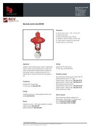
Fig.1. Mounting the <st<strong>ro</strong>ng>CMK</st<strong>ro</strong>ng>-<st<strong>ro</strong>ng>02</st<strong>ro</strong>ng> <st<strong>ro</strong>ng>corrector</st<strong>ro</strong>ng>, version 1.<br />
<st<strong>ro</strong>ng>CMK</st<strong>ro</strong>ng>-<st<strong>ro</strong>ng>02</st<strong>ro</strong>ng> Operating and maintenance manual 9
Fig. 2. Mounting the <st<strong>ro</strong>ng>CMK</st<strong>ro</strong>ng>-<st<strong>ro</strong>ng>02</st<strong>ro</strong>ng> <st<strong>ro</strong>ng>corrector</st<strong>ro</strong>ng>, version 2.<br />
.<br />
<st<strong>ro</strong>ng>CMK</st<strong>ro</strong>ng>-<st<strong>ro</strong>ng>02</st<strong>ro</strong>ng> Operating and maintenance manual 10
Fig. 3. Mounting the <st<strong>ro</strong>ng>CMK</st<strong>ro</strong>ng>-<st<strong>ro</strong>ng>02</st<strong>ro</strong>ng> <st<strong>ro</strong>ng>corrector</st<strong>ro</strong>ng>, version 3.<br />
<st<strong>ro</strong>ng>CMK</st<strong>ro</strong>ng>-<st<strong>ro</strong>ng>02</st<strong>ro</strong>ng> Operating and maintenance manual 11
The installation of the <st<strong>ro</strong>ng>CMK</st<strong>ro</strong>ng>-<st<strong>ro</strong>ng>02</st<strong>ro</strong>ng> <st<strong>ro</strong>ng>corrector</st<strong>ro</strong>ng> may be differentiated into few stages:<br />
1. Install of the <st<strong>ro</strong>ng>corrector</st<strong>ro</strong>ng> nearby the gas meter at a place easily accessible for maintenance<br />
and service. To do this one should use a holder app<strong>ro</strong>priate for the gas meter and the<br />
mounting conditions in the measuring station. The offer of COMMON S.A. firm includes a few<br />
types of holders for fixing the <st<strong>ro</strong>ng>corrector</st<strong>ro</strong>ng> on the measuring section or on the gas meter. When<br />
selecting the place for the <st<strong>ro</strong>ng>corrector</st<strong>ro</strong>ng> take into account that the pressure sensor inside the<br />
<st<strong>ro</strong>ng>CMK</st<strong>ro</strong>ng>-<st<strong>ro</strong>ng>02</st<strong>ro</strong>ng> must not be located below the pressure measurement stub pipe of the gas meter.<br />
2. Connection of the pressure measurement. The pressure measurement stub pipe located<br />
on the gas meter should be connected with the <st<strong>ro</strong>ng>corrector</st<strong>ro</strong>ng>’s pressure sensor with the help of<br />
impulse piping. It should also be installed the three-way cock to facilitate later servicing of the<br />
<st<strong>ro</strong>ng>corrector</st<strong>ro</strong>ng> or connecting the cont<strong>ro</strong>l manometer. The offer of COMMON S.A. firm also<br />
includes the CKMT three-way cock (made by COMMON S.A.).<br />
3. The connection of basic measurements. To perform the basic function: the accounting<br />
operation, it is necessary to connect the low frequency (LF) transmitter circuit f<strong>ro</strong>m the gas<br />
meter head and the temperature sensor circuit. Below it is given the description of the<br />
terminal strip:<br />
Pt 1000<br />
1 2<br />
LF<br />
1 2<br />
The <st<strong>ro</strong>ng>corrector</st<strong>ro</strong>ng> is adapted for operation with the reed contact LF transmitter (every gas meter<br />
of COMMON firm is equipped with it as a standard). The polarity of the LF transmitter and<br />
the Pt 1000 sensor is of no importance.<br />
<st<strong>ro</strong>ng>CMK</st<strong>ro</strong>ng>-<st<strong>ro</strong>ng>02</st<strong>ro</strong>ng> Operating and maintenance manual 12
Example of mounting the Pt 1000 temperature sensor<br />
1. outlet section,<br />
2. temperature sensor Pt 1000,<br />
3. thermometric sleeve<br />
4. seal<br />
4. Connecting the additional measurements. The description of the terminal strip is given<br />
below. Pay attention to the polarity of the connecting circuits (if the circuits of the connecting<br />
devices have the defined polarity). Because the <st<strong>ro</strong>ng>corrector</st<strong>ro</strong>ng> is entirely an intrinsically safe<br />
device, all circuits must be connected to the circuits of the intrinsically safe devices; in other<br />
cases the explosion p<strong>ro</strong>of barriers should be used.<br />
IN 2 OUT 4<br />
- + - +<br />
IN 1 OUT 3<br />
- + - +<br />
HF<br />
- +<br />
The input circuits marked IN1 and IN2 can cooperate with the intrinsically safe circuits<br />
of the simply devices and in particular with contacts of the switching elements<br />
app<strong>ro</strong>ved for operation in the intrinsically safe circuits.<br />
The input circuits marked OUT3 and OUT3 can cooperate with the external intrinsically<br />
safe circuits of ia or ib category. Maximum value of capacitance and inductance for this<br />
circuit should be assumed according to the criterion of the connected circuit, taking into<br />
consideration the internal C i and L i parameters<br />
NOTICE:<br />
For the option with the digital PC-70 pressure transmitter supplied f<strong>ro</strong>m the<br />
<st<strong>ro</strong>ng>corrector</st<strong>ro</strong>ng>’s battery the OUT3 is used for supplying it.<br />
<st<strong>ro</strong>ng>CMK</st<strong>ro</strong>ng>-<st<strong>ro</strong>ng>02</st<strong>ro</strong>ng> Operating and maintenance manual 13
5. Connecting the power supply and data transmission in the RS-GAZ2 standard.<br />
The converter (e.g. CZAK-<st<strong>ro</strong>ng>02</st<strong>ro</strong>ng>, CBS-<st<strong>ro</strong>ng>02</st<strong>ro</strong>ng>, CAK-<st<strong>ro</strong>ng>02</st<strong>ro</strong>ng>, and CAKGSM-<st<strong>ro</strong>ng>02</st<strong>ro</strong>ng>) must be installed<br />
outside the explosion zone. The installation conditions are described in the converter<br />
documentation. The app<strong>ro</strong>priate terminals of the <st<strong>ro</strong>ng>CMK</st<strong>ro</strong>ng>-<st<strong>ro</strong>ng>02</st<strong>ro</strong>ng> <st<strong>ro</strong>ng>corrector</st<strong>ro</strong>ng>’s terminal strip<br />
should be connected to the adequately marked connectors in the converter. Attention<br />
should be paid to the description of the terminals because their location in the <st<strong>ro</strong>ng>corrector</st<strong>ro</strong>ng><br />
and the converter is not the same.<br />
The <st<strong>ro</strong>ng>CMK</st<strong>ro</strong>ng>-<st<strong>ro</strong>ng>02</st<strong>ro</strong>ng> <st<strong>ro</strong>ng>corrector</st<strong>ro</strong>ng> terminal strip:<br />
A B A B<br />
TUCHEL connector on the casing:<br />
V+<br />
RS 1 RS 2<br />
V+ ┴ V+ ┴<br />
View f<strong>ro</strong>m the f<strong>ro</strong>nt of Tuchel male socket on<br />
the <st<strong>ro</strong>ng>corrector</st<strong>ro</strong>ng>’s casing<br />
6. Connecting the PC-70 digital pressure converter. The <st<strong>ro</strong>ng>CMK</st<strong>ro</strong>ng>-<st<strong>ro</strong>ng>02</st<strong>ro</strong>ng> <st<strong>ro</strong>ng>corrector</st<strong>ro</strong>ng> ensures<br />
the possibility of connecting and logging the additional pressure measurements with<br />
the help of the PC-70 digital pressure converters. Cooperation between the <st<strong>ro</strong>ng>CMK</st<strong>ro</strong>ng>-<st<strong>ro</strong>ng>02</st<strong>ro</strong>ng><br />
<st<strong>ro</strong>ng>corrector</st<strong>ro</strong>ng> and the PC-70 converters is performed with two version of supply:<br />
• The <st<strong>ro</strong>ng>CMK</st<strong>ro</strong>ng>-<st<strong>ro</strong>ng>02</st<strong>ro</strong>ng> <st<strong>ro</strong>ng>corrector</st<strong>ro</strong>ng> uses the external power supply. The supply can be<br />
transferred by a suitable transmission converter (recommended for the mains<br />
supply: two-channel converter with the CZAK-<st<strong>ro</strong>ng>02</st<strong>ro</strong>ng> power converter, the CBS-<st<strong>ro</strong>ng>02</st<strong>ro</strong>ng><br />
signaling barrier; recommended for supply f<strong>ro</strong>m the battery and the solar battery:<br />
CAKGSM-<st<strong>ro</strong>ng>02</st<strong>ro</strong>ng> converter) – possible connection of two sensors.<br />
• The <st<strong>ro</strong>ng>CMK</st<strong>ro</strong>ng>-<st<strong>ro</strong>ng>02</st<strong>ro</strong>ng> <st<strong>ro</strong>ng>corrector</st<strong>ro</strong>ng> uses its own battery supply (only for the <st<strong>ro</strong>ng>corrector</st<strong>ro</strong>ng> in „B”<br />
version) – possible connection of one sensor.<br />
The PC-70 pressure converter is placed in the casing with the stub pipe with the M20x1,5<br />
external thread and dimensions given below.<br />
Stub pipe dimensions of the PC-70 converter.<br />
2 1<br />
5<br />
3 4<br />
1 - RSGAZ 2 B<br />
2 - RSGAZ 2 A<br />
4 - + SUPPLY<br />
5 - ⊥ EARTH<br />
Description and designation of the PC-70 converter connector leads<br />
<st<strong>ro</strong>ng>CMK</st<strong>ro</strong>ng>-<st<strong>ro</strong>ng>02</st<strong>ro</strong>ng> Operating and maintenance manual 14
Connection of the PC-70 converter with the <st<strong>ro</strong>ng>CMK</st<strong>ro</strong>ng>-<st<strong>ro</strong>ng>02</st<strong>ro</strong>ng> <st<strong>ro</strong>ng>corrector</st<strong>ro</strong>ng> and the power supply/ the<br />
CZAK-<st<strong>ro</strong>ng>02</st<strong>ro</strong>ng> converter (mains supply):<br />
230 V<br />
RS232<br />
CZAK-<st<strong>ro</strong>ng>02</st<strong>ro</strong>ng><br />
E X zone<br />
4 x LIYY 0,25 mm 2<br />
(or 0,5 lub 1) mm 2<br />
<st<strong>ro</strong>ng>CMK</st<strong>ro</strong>ng>-<st<strong>ro</strong>ng>02</st<strong>ro</strong>ng><br />
RS1 RS2<br />
4 x LIYY 0,25 mm 2<br />
(Notice! Supply to RS1)<br />
PC 70<br />
CZAK-<st<strong>ro</strong>ng>02</st<strong>ro</strong>ng> <st<strong>ro</strong>ng>CMK</st<strong>ro</strong>ng>-<st<strong>ro</strong>ng>02</st<strong>ro</strong>ng> PC-70 (1) PC-70 (2)<br />
A (COM1) A (RS 1)<br />
B (COM1) B (RS 1)<br />
A (RS 2) 2 2<br />
B (RS 2) 1 1<br />
V+ (COM1) V+ (RS 1) 4 4<br />
┴ (COM1) ┴ (RS 1) 5 5<br />
Maximum distance between the <st<strong>ro</strong>ng>CMK</st<strong>ro</strong>ng>-<st<strong>ro</strong>ng>02</st<strong>ro</strong>ng> <st<strong>ro</strong>ng>corrector</st<strong>ro</strong>ng> and the PC70 converter with the given<br />
cable c<strong>ro</strong>ss section (0,25 mm2) should be shorter than 25 meters.<br />
The cables supplying the PC-70 converter should be connected together with the supply<br />
f<strong>ro</strong>m the CZAK-<st<strong>ro</strong>ng>02</st<strong>ro</strong>ng> converter (to the same terminals on the RS 1 port terminal strip in the<br />
<st<strong>ro</strong>ng>CMK</st<strong>ro</strong>ng>-<st<strong>ro</strong>ng>02</st<strong>ro</strong>ng><st<strong>ro</strong>ng>corrector</st<strong>ro</strong>ng>).<br />
Connect the second PC-70 converter to the same terminals as the first one.<br />
Connection of the PC-70 converter with the <st<strong>ro</strong>ng>CMK</st<strong>ro</strong>ng>-<st<strong>ro</strong>ng>02</st<strong>ro</strong>ng> <st<strong>ro</strong>ng>corrector</st<strong>ro</strong>ng> (battery supply):<br />
<st<strong>ro</strong>ng>CMK</st<strong>ro</strong>ng>-<st<strong>ro</strong>ng>02</st<strong>ro</strong>ng><br />
RS1 RS2<br />
PC 70<br />
<st<strong>ro</strong>ng>CMK</st<strong>ro</strong>ng>-<st<strong>ro</strong>ng>02</st<strong>ro</strong>ng> PC-70<br />
A (RS 2) 2<br />
B (RS 2) 1<br />
– OUT 3 4<br />
┴ (RS 2) 5<br />
4 x LIYY 0,25 mm 2<br />
The circuits going out f<strong>ro</strong>m the explosion zone can be led in one bundle.<br />
<st<strong>ro</strong>ng>CMK</st<strong>ro</strong>ng>-<st<strong>ro</strong>ng>02</st<strong>ro</strong>ng> Operating and maintenance manual 15
4.3. Parameters of use<br />
Below there are given the electrical parameters related to individual terminals and<br />
connectors of the device:<br />
RS-GAZ2:<br />
The V+, terminals of the RS1 and RS2 terminal strip and the 4-5 pins of TUCHEL<br />
connector on the casing have the following parameters:<br />
U i =7,5V, I i =0,45A, P i =0,85W, L i ≈0, C i
5. Operating the <st<strong>ro</strong>ng>corrector</st<strong>ro</strong>ng><br />
The communication of the user with the <st<strong>ro</strong>ng>corrector</st<strong>ro</strong>ng> is performed by means of keyboard and<br />
four-line alphanumeric display. The keyboard consists of four keys Esc, Enter, and the ↓,<br />
↑ ar<strong>ro</strong>ws.<br />
The Enter key causes moving to the submenu, changing the active position in the editor<br />
or storing the entered value.<br />
The Esc key causes return to the upper menu or exit f<strong>ro</strong>m the value editing mode.<br />
The ↓ and ↑ keys cause changing the submenu, displaying the consecutive sequence of<br />
information, which do not hold on one screen and setting the parameters in case of<br />
modification of the settings.<br />
When the <st<strong>ro</strong>ng>corrector</st<strong>ro</strong>ng> is fallen asleep (display is not active) it should be stimulated by<br />
pressing any key. The display is turned off automatically after 30 seconds since the<br />
moment one stopped using the keyboard (with the external supply the display remains<br />
switched on all the time).<br />
The following screens are displayed (moving to the consecutive screen is done after<br />
pressing the ↓ key):<br />
1) Main counters and <st<strong>ro</strong>ng>volume</st<strong>ro</strong>ng> flows:<br />
• uncorrected <st<strong>ro</strong>ng>volume</st<strong>ro</strong>ng> (V1),<br />
• standard <st<strong>ro</strong>ng>volume</st<strong>ro</strong>ng> (Vn),<br />
• real flow (Q1),<br />
• standard flow (Qn).<br />
V1 = 0009543.0 m3<br />
Vn = 18520.0 m3<br />
Q1 =s 171.5 m3/h<br />
Qn = 188.9 m3/h<br />
NOTICE:<br />
The ‘s’ character on the right of the ‘=’ sign means that the simulation is switched<br />
on.<br />
2) Gas parameters and correction values:<br />
• compressibility coefficient (K1),<br />
• correction coefficient (F),<br />
• momentary gas temperature (t1),<br />
• momentary gas pressure (p1).<br />
Alarms:<br />
K1 = 0.997546<br />
F = 2.386054<br />
t1 =s 19.8 °C<br />
p1= 258.7 kPa<br />
• The ‘’ sign at the ‘t1’ or ‘p1’ labels means that the <st<strong>ro</strong>ng>corrector</st<strong>ro</strong>ng> was not able to<br />
take the p<strong>ro</strong>per measurement of the given value – the value f<strong>ro</strong>m the previous<br />
measurement remains on the display.<br />
• The sign ‘!’ means c<strong>ro</strong>ssing of the defined alarm limits, flashing ‘!’ sign means<br />
c<strong>ro</strong>ssing the defined converter ranges and the NAN value – converter failure.<br />
<st<strong>ro</strong>ng>CMK</st<strong>ro</strong>ng>-<st<strong>ro</strong>ng>02</st<strong>ro</strong>ng> Operating and maintenance manual 17
The measurements of the p1, t1 values and the calculations of correction coefficient in the<br />
battery supply mode are performed every 30 seconds, and with external supply every 2<br />
seconds.<br />
The calculation of the compressibility coefficient is performer every 30 seconds on the<br />
base of the mean temperature and the pressure values for the last 30 seconds.<br />
3) Gas consumption<br />
- value f<strong>ro</strong>m the beginning of the hour (ph),<br />
- expected consumption to the end of the hour (eph),<br />
-=- -=ph<br />
= 12.69 m3<br />
eph = 542.71 m3<br />
-=- -=-<br />
Expected hourly consumption – way of calculation<br />
The gas quantity that will be consumed to the end of the hour is calculated on the<br />
base of the standard flow current value, and with assumption of its invariability. Then<br />
the value is increased by the consumption since the beginning of the clock hour.<br />
4) The condition of the <st<strong>ro</strong>ng>corrector</st<strong>ro</strong>ng>’s supply and the battery capacity.<br />
Mains operation<br />
Battery condition 85%<br />
˜˜˜˜˜˜˜˜˜˜˜˜˜•••<br />
Battery operation<br />
Battery condition 85%<br />
˜˜˜˜˜˜˜˜˜˜˜˜˜•••<br />
After reaching the state of 5% the <st<strong>ro</strong>ng>corrector</st<strong>ro</strong>ng> starts logging the alarm ‘Low supply voltage’,<br />
and below 1% the <st<strong>ro</strong>ng>corrector</st<strong>ro</strong>ng>’s and logger’s modules are switched off. The data<br />
transmission still can be performed by eg.: the OptoGAZ interface.<br />
5.1. Main menu<br />
After pressing the Enter key the main menu is displayed. The selection is done with the<br />
help of the ↑ and ↓ keys. The selection is confirmed by the Enter key.<br />
5.2. Algorithm constants<br />
→algorithm constants<br />
current data<br />
logged data<br />
gas composition<br />
serial connections<br />
configuration<br />
plate<br />
clock<br />
The presented information is split to the data concerning the <st<strong>ro</strong>ng>volume</st<strong>ro</strong>ng> and the gas<br />
compressibility coefficient determination method.<br />
The following data are displayed: HF, LF pulse weight, moment of logging the logged data<br />
and the current source of Qr and Vr signal.<br />
<st<strong>ro</strong>ng>CMK</st<strong>ro</strong>ng>-<st<strong>ro</strong>ng>02</st<strong>ro</strong>ng> Operating and maintenance manual 18
HF = 3228.10 imp/m3<br />
LF = 1.00 imp/m3<br />
Q:LF[] V:LF<br />
R+ [dt=10min] K+<br />
Information concerning the signal source used for determination of the Q flow:<br />
- Q : LF [LF] - the flow is calculated f<strong>ro</strong>m the low frequency reed contact transmitter LF,<br />
- Q : HF [HF] - the flow is calculated f<strong>ro</strong>m the high frequency transmitter HF.<br />
In case the setting is present in the square bracket (Q : HF []) the <st<strong>ro</strong>ng>corrector</st<strong>ro</strong>ng> selects<br />
by itself the flow signal source depending on signal availability (eg. the <st<strong>ro</strong>ng>corrector</st<strong>ro</strong>ng><br />
determines the flow Q f<strong>ro</strong>m the HF transmitter, in case of failure in the external supply the<br />
<st<strong>ro</strong>ng>corrector</st<strong>ro</strong>ng> automatically switches over to determination of Q f<strong>ro</strong>m the LF transmitter).<br />
The +/- signs at the R and K characters means the status of switching on/ switching off the<br />
<st<strong>ro</strong>ng>corrector</st<strong>ro</strong>ng>’s (R) and data logger’s (K) modules.<br />
When the accounting data logging period is to be changed and it was chosen the<br />
synch<strong>ro</strong>nization with the beginning of the accounting day, the app<strong>ro</strong>priate information is<br />
displayed:<br />
HF = 3228.10 imp/m3<br />
LF = 1.00 imp/m3<br />
Q:LF[] V:LF<br />
R+ [dt=5→10min] K+<br />
After pressing the ar<strong>ro</strong>w key there are displayed:<br />
• standard temperature,<br />
• standard pressure,<br />
• applied calculation method,<br />
• type of gas mixture.<br />
tn = 273.15 K<br />
pn = 101325 Pa<br />
K1 wg GERG-88<br />
natural gas<br />
The calculation method matches with the selected gas composition. As a standard the<br />
<st<strong>ro</strong>ng>corrector</st<strong>ro</strong>ng> is p<strong>ro</strong>vided with the GERG-88 algorithm, the following algorithms are also<br />
available on the order:<br />
Natural gas:<br />
GERG-91, AGA-NX19<br />
City gas/coke-oven gas:<br />
Beattie-Bridgeman,<br />
Others (CO 2 , hyd<strong>ro</strong>gen, nit<strong>ro</strong>gen, argon, air, p<strong>ro</strong>pane-buthanee and others):<br />
Peng-Robinson, Van der Waals, Redlich-Kwong, Soeve-Redlich-Kwong, virial equation.<br />
5.3. Current data<br />
In this menu there are displayed parameters currently determined by the <st<strong>ro</strong>ng>CMK</st<strong>ro</strong>ng>-<st<strong>ro</strong>ng>02</st<strong>ro</strong>ng><br />
<st<strong>ro</strong>ng>corrector</st<strong>ro</strong>ng>. Pressing the ↓ key causes moving to the consecutive set of parameters.<br />
1) Main counters:<br />
- gas <st<strong>ro</strong>ng>volume</st<strong>ro</strong>ng> in real conditions V1,<br />
<st<strong>ro</strong>ng>CMK</st<strong>ro</strong>ng>-<st<strong>ro</strong>ng>02</st<strong>ro</strong>ng> Operating and maintenance manual 19
- gas <st<strong>ro</strong>ng>volume</st<strong>ro</strong>ng> in standard conditions Vn,<br />
- energy counters for standard conditions E (the subscript adequately means:<br />
‘s’ – energy calculated with the use of heat of combustion, ‘i’ – calorific value).<br />
- mass for standard conditions M.<br />
V1 =<br />
Vn =<br />
Es =<br />
M =<br />
0010786.0 m3<br />
21139 m3<br />
142842 MJ<br />
15650 kg<br />
2) Flows:<br />
- gas flow in real conditions Q1,<br />
- gas velocity in the pipeline U1 (to calculate this value p<strong>ro</strong>perly it is required the<br />
information about cooperating gas meter and especially DN parameter),<br />
- normal energy flow,<br />
- mass flow<br />
Q1 =<br />
U1 =<br />
Eq =<br />
Mq =<br />
171.75 m3/h<br />
2.18 m/s<br />
7555.62 MJ/h<br />
140.34 kg/h<br />
3) Current correction values:<br />
- compressibility coefficient K1,<br />
- correction coefficient F,<br />
- gas real temperature,<br />
- gas real pressure.<br />
K1 = 1.000179<br />
F = 1.105173<br />
t1 = 19.8 °C<br />
p1 = 119.9 kPa<br />
3) Digital in/out:<br />
- HF pulse weight measured by the <st<strong>ro</strong>ng>corrector</st<strong>ro</strong>ng> with reference to 1 m 3 - rHF,<br />
- calculated HF constant er<strong>ro</strong>r with reference to the p<strong>ro</strong>grammed value - eHF,<br />
- state of individual digital in/out, example:<br />
I1 - - I1 output inactive<br />
I1+ - I1 output active, input signal below the filtering threshold<br />
(described in the chapter algorithm constants | signalling),<br />
I1++ I1 output active, input signal above the filtering threshold<br />
(described in the chapter algorithm constants | signalling),<br />
-O4 - O4 output inactive,<br />
+O4- O4 output active, electrical state of the output - open,<br />
+O4+ O4 output active, electrical state of the output - closed<br />
- day, time and maximum number of pulses counted in one minute.<br />
<st<strong>ro</strong>ng>CMK</st<strong>ro</strong>ng>-<st<strong>ro</strong>ng>02</st<strong>ro</strong>ng> Operating and maintenance manual 20
4) Real parameters of the mixture:<br />
rHF= 900.0 imp/m3<br />
eHF= 0.0000 %<br />
I1++ I2-- -O3- -O4-<br />
Imax 1/12:15 = 7<br />
- real gas density in measuring conditions ρ1,<br />
- relative gas density in measuring conditions d1,<br />
- real heat of combustion Hs1,<br />
- real calorific value Hi1,<br />
ρ1 =<br />
d1 =<br />
Hs1=<br />
Hi1=<br />
0.8306 kg/m3<br />
0.6424 kg/m3<br />
25.8587 MJ/m3<br />
23.3273 MJ/m3<br />
5) Peak consumption for standard values<br />
- values calculated for each day,<br />
- monthly values,<br />
With the Enter key we may change the peak value displaying mode. The following values<br />
will be displayed in turn:<br />
• for daily peak:<br />
− permanent window values (maximum consumption between completed hours),<br />
− slide window values (maximum consumption for the 60 minute period),<br />
− current value (consumption for the last 60 minutes).<br />
• for monthly peak:<br />
− permanent window values,<br />
− slide window values.<br />
The date, moment of the beginning and value of the adequate consumption are<br />
always given.<br />
Daily consumption – way of calculation<br />
The flowing gas standard <st<strong>ro</strong>ng>volume</st<strong>ro</strong>ng> increase is calculated during every clock hour. The<br />
biggest of them, counting f<strong>ro</strong>m the beginning of the day (as a standard it is 22.00 hour) is<br />
stored in the database as hourly peak together with the signature of the moment of<br />
occurrence.<br />
This cycle is repeated independently for every day.<br />
Daily peak<br />
permanent widow<br />
qh = 482.82 m3/h<br />
06/01/2001 01:00<br />
Daily peak<br />
slide window<br />
qh = 578.71 m3/h<br />
06/01/2001 01:28<br />
Daily peak<br />
current value<br />
qh = 695.33 m3/h<br />
06/01/2001 06:51<br />
<st<strong>ro</strong>ng>CMK</st<strong>ro</strong>ng>-<st<strong>ro</strong>ng>02</st<strong>ro</strong>ng> Operating and maintenance manual 21
Monthly consumption – way of calculation<br />
F<strong>ro</strong>m the maximum consumption values determined every day the maximum value for the<br />
month’s period is selected and stored in the database as a monthly peak.<br />
This cycle is repeated independently for each day.<br />
Monthly peak<br />
permanent window<br />
qh = 575.23 m3/h<br />
<st<strong>ro</strong>ng>02</st<strong>ro</strong>ng>/01/2001 05:00<br />
Monthly peak<br />
slide window<br />
qh = 578.71 m3/h<br />
06/01/2001 01:28<br />
6) Current value for external sensors:<br />
- pressure value,<br />
- calculated gradient value,<br />
- calculated percentage value of the change.<br />
Outlet pressure 1<br />
Pw = 338.1 kPa<br />
+ G= 7.79º Z= 2.01%<br />
Outlet pressure 2<br />
Lack of reading<br />
When the measurement f<strong>ro</strong>m the sensor is switched off or the <st<strong>ro</strong>ng>corrector</st<strong>ro</strong>ng> detects the lack of<br />
communication with the transducer for 60 second period, the „Lack of reading” description<br />
is displayed.<br />
5.4. Logged values<br />
The four-item submenu is displayed:<br />
→alarm list<br />
daily data<br />
monthly data<br />
accounting data<br />
After selecting the item, the information about number of records written in the memory is<br />
displayed; the percentage of the memory available for recording is given in brackets.<br />
Number of logs<br />
629 (98%)<br />
↑ the most recent data<br />
↓ the oldest data<br />
<st<strong>ro</strong>ng>CMK</st<strong>ro</strong>ng>-<st<strong>ro</strong>ng>02</st<strong>ro</strong>ng> Operating and maintenance manual 22
Alarm list contains:<br />
• date and the moment of the start of the event,<br />
• date and the moment of the end of the event or the identifier of the software or the<br />
user,<br />
• estimated gas standard <st<strong>ro</strong>ng>volume</st<strong>ro</strong>ng> increase (if it was calculated),<br />
• shortened event description.<br />
The list can contain maximum up to 4000 logs.<br />
P: 6/01/01 00:33.35<br />
K: 6/01/01 00:34.09<br />
dVn = 11.5 m3<br />
P limit exceeded<br />
Daily data include:<br />
On each screen:<br />
• date of logging,<br />
On the first screen:<br />
• state of the counter at the end of the day (V1),<br />
• state of the main counter at the end of the day (Vn),<br />
On the second screen:<br />
• time and value of maximum hourly consumption (with the slide window) – (pm),<br />
• time and value of maximum hourly consumption (between completed hours) – (ph),<br />
It is always given the moment of the beginning of the peak.<br />
Switching over between screens is done after pressing the Enter key. The data f<strong>ro</strong>m the<br />
last 60 months are stored.<br />
V1 =<br />
Vn =<br />
Record 9/9<br />
1/01/2001<br />
00<st<strong>ro</strong>ng>02</st<strong>ro</strong>ng>500.0 m3<br />
208125.2 m3<br />
Record 9/9<br />
1/01/2001<br />
pm = 1678 m3 21:25<br />
ph = 1677 m3 22:00<br />
Monthly data include:<br />
On each screen:<br />
• date of logging,<br />
On the first screen:<br />
• state of the real counter at the end of the month (V1),<br />
• state of the main counter at the end of the month (Vn),<br />
On the second screen:<br />
• time and value of maximum hourly consumption (with the slide window) – (pm),<br />
• time and value of maximum hourly consumption (between completed hours)– (ph).<br />
It is always given the moment of beginning of the peak.<br />
<st<strong>ro</strong>ng>CMK</st<strong>ro</strong>ng>-<st<strong>ro</strong>ng>02</st<strong>ro</strong>ng> Operating and maintenance manual 23
Switching over between screens is done after pressing the Enter key. The data f<strong>ro</strong>m the<br />
beginning of the <st<strong>ro</strong>ng>corrector</st<strong>ro</strong>ng> use are stored.<br />
V1 =<br />
Vn =<br />
Record 4/2<br />
January 2000<br />
00<st<strong>ro</strong>ng>02</st<strong>ro</strong>ng>500.0 m3<br />
208125.2 m3<br />
Record 4/2<br />
January 2000<br />
pm = 1678m3 21:25/01<br />
ph = 1677m3 22:00/01<br />
Accounting data include:<br />
On each screen:<br />
• date and time of logging,<br />
On the first screen:<br />
• gas real <st<strong>ro</strong>ng>volume</st<strong>ro</strong>ng> increase,<br />
• gas standard <st<strong>ro</strong>ng>volume</st<strong>ro</strong>ng> increase,<br />
On the second screen:<br />
• mean gas temperature for the logging interval,<br />
• mean gas absolute pressure for the logging period ,<br />
On the third screen:<br />
• reserve 1 – pressure value f<strong>ro</strong>m the first PC-70 sensor,<br />
• reserve 2 – pressure value f<strong>ro</strong>m the second PC-70 sensor.<br />
Switching over between screens is done after pressing the Enter key.<br />
5.5. Gas composition<br />
Record 9/1<st<strong>ro</strong>ng>02</st<strong>ro</strong>ng>9<br />
1/01/2000 07:00<br />
dV1 = 00<st<strong>ro</strong>ng>02</st<strong>ro</strong>ng>500.0 m3<br />
dVn = 2501.7 m3<br />
Record 9/1<st<strong>ro</strong>ng>02</st<strong>ro</strong>ng>9<br />
1/01/2000 07:00<br />
t1 = 19.9 °C<br />
p1 = 99.8 kPa<br />
Record 9/1<st<strong>ro</strong>ng>02</st<strong>ro</strong>ng>9<br />
1/01/2000 07:00<br />
r1 = 23.6 °C<br />
r2 = 1.0007<br />
It is displayed the submenu including the following items:<br />
→ gas parameters<br />
gas coefficient<br />
gas composition<br />
Gas parameters (for GERG-88 calculation method):<br />
• molar heat of combustion (Hch),<br />
<st<strong>ro</strong>ng>CMK</st<strong>ro</strong>ng>-<st<strong>ro</strong>ng>02</st<strong>ro</strong>ng> Operating and maintenance manual 24
• mole fraction CH<br />
• mole fraction N 2<br />
Hch 916.64100<br />
CH participation 0.981822<br />
N2 participation 0.015839<br />
Gas coefficients (for GERG-88 calculation method):<br />
• standard compressibility coefficient (Zn),<br />
• standard density (ρn),<br />
• heat of combustion (Hs),<br />
• calorific value (Hi).<br />
Zn 0.9975<br />
ρn 0.7533<br />
Hs 40.2542<br />
Hi 36.3136<br />
In gas composition menu it is displayed the percentage content (<st<strong>ro</strong>ng>volume</st<strong>ro</strong>ng>tric or molar) of<br />
all gas components in the defined mixture.<br />
5.6. Serial connections<br />
gas composition<br />
natural gas<br />
<st<strong>ro</strong>ng>volume</st<strong>ro</strong>ng>tric composition<br />
methane 95.520<br />
ethane 01.880<br />
p<strong>ro</strong>pane 00.490<br />
n-buthane 00.150<br />
....<br />
oxygen 00.000<br />
carbon dioxide 00.230<br />
sulfur dioxide 00.000<br />
air 00.000<br />
The option serial connection is discussed in chapter 6. Configuration of the <st<strong>ro</strong>ng>corrector</st<strong>ro</strong>ng>.<br />
5.7. Configuration<br />
The option configuration is discussed in chapter 6. Configuration of the <st<strong>ro</strong>ng>corrector</st<strong>ro</strong>ng>.<br />
5.8. Nameplate<br />
It displays the information of the p<strong>ro</strong>duct, manufacturer and version of internal software.<br />
Factory number 41059<br />
Year of p<strong>ro</strong>duction 2000<br />
Software version<br />
GM1/GM2 2xPC70/bat<br />
Common 91-205 Łódź<br />
Aleksand<strong>ro</strong>wska 67/93<br />
tel: /+4842/ 6135600<br />
fax: /+4842/ 6135698<br />
<st<strong>ro</strong>ng>CMK</st<strong>ro</strong>ng>-<st<strong>ro</strong>ng>02</st<strong>ro</strong>ng> Operating and maintenance manual 25
5.9. Clock<br />
Software ID<br />
1.0.4.0a<br />
Build-time<br />
08-07-06 12:35:22<br />
After selecting this menu item the following information is displayed:<br />
On the first screen: current date, day of the week and time.<br />
2006-07-12<br />
Wednesday<br />
13:14:36<br />
On the second screen: date of changing the time to summer time and standard time.<br />
If the date has not been p<strong>ro</strong>grammed or the <st<strong>ro</strong>ng>corrector</st<strong>ro</strong>ng> has changed the time, the<br />
description „not set” is displayed.<br />
summer time<br />
31/03/20<st<strong>ro</strong>ng>02</st<strong>ro</strong>ng> <st<strong>ro</strong>ng>02</st<strong>ro</strong>ng>:00<br />
standard time<br />
28/10/2001 03:00<br />
On the third screen: the period of time during which the <st<strong>ro</strong>ng>corrector</st<strong>ro</strong>ng> was activated without<br />
external supply.<br />
Total time of<br />
battery operation<br />
<st<strong>ro</strong>ng>02</st<strong>ro</strong>ng>:27:16<br />
<st<strong>ro</strong>ng>CMK</st<strong>ro</strong>ng>-<st<strong>ro</strong>ng>02</st<strong>ro</strong>ng> Operating and maintenance manual 26
6. Configuration of the <st<strong>ro</strong>ng>corrector</st<strong>ro</strong>ng><br />
Before performing the remote configuration of the <st<strong>ro</strong>ng>corrector</st<strong>ro</strong>ng> the transmission parameters<br />
of serial connections should be set. To do this the function serial connections should be<br />
selected f<strong>ro</strong>m the main menu. The following screen will appear:<br />
→port com1/opto<br />
port com2<br />
gazmodem<br />
modbus ascii/rtu<br />
NOTICE:<br />
Since the software version 1.0.2.20b after selecting this menu item the screen<br />
appears with collected information about serial connections parameters, as below.<br />
After pressing the Enter key we move to configuration of the communication ports<br />
parameters.<br />
Com1:<br />
GM:55<br />
Com2:<br />
GM:99<br />
9600,8,N,1<br />
Modbus:0<st<strong>ro</strong>ng>02</st<strong>ro</strong>ng><br />
57600,8,N,1<br />
Modbus:0<st<strong>ro</strong>ng>02</st<strong>ro</strong>ng><br />
The options port com1/opto and port com2 are used for setting the transmission<br />
parameters of adequate COM1 and COM2 ports. On the following drawing the following<br />
parameters are seen (f<strong>ro</strong>m the left): transmission speed, data bits, parity, stop bits.<br />
port com1/opto<br />
4800 08 N 01<br />
^^^^^<br />
↑↓ digit change<br />
The change of the selected parameter (distinguished by ^^^^^ signs) is done with the<br />
help of the ↑ and ↓ keys. Moving to the next modification field is performed after pressing<br />
the Enter key. The modification is finished after pressing the Esc key. If any changes had<br />
been entered it will appear the screen with the request for their confirmation, i.e.:<br />
port com1/opto<br />
9600 08 N 01<br />
ESC-No<br />
ENTER–Yes<br />
After pressing the Esc key the changes will be rejected; the Enter key confirms changes<br />
– the reconfiguration of the app<strong>ro</strong>priate port takes place.<br />
In gazmodem option the addresses of Gaz-Modem p<strong>ro</strong>tocol are set. The addresses are<br />
p<strong>ro</strong>grammed in turn for COM1 and COM2 port.<br />
<st<strong>ro</strong>ng>CMK</st<strong>ro</strong>ng>-<st<strong>ro</strong>ng>02</st<strong>ro</strong>ng> Operating and maintenance manual 27
gazmodem<br />
1:00055 2:00099<br />
^<br />
↑↓ digit change<br />
In the modbus ascii/rtu option it is set the Modus p<strong>ro</strong>tocol address common for both<br />
communication connections.<br />
The configuration of the <st<strong>ro</strong>ng>CMK</st<strong>ro</strong>ng>-<st<strong>ro</strong>ng>02</st<strong>ro</strong>ng> <st<strong>ro</strong>ng>corrector</st<strong>ro</strong>ng> can be done in two ways:<br />
1. By the use of a computer and the p<strong>ro</strong>per service p<strong>ro</strong>gramme. Owing to the fact<br />
that the <st<strong>ro</strong>ng>CMK</st<strong>ro</strong>ng>-<st<strong>ro</strong>ng>02</st<strong>ro</strong>ng> <st<strong>ro</strong>ng>corrector</st<strong>ro</strong>ng> is the functional extension of the <st<strong>ro</strong>ng>CMK</st<strong>ro</strong>ng>-01 <st<strong>ro</strong>ng>corrector</st<strong>ro</strong>ng>, the<br />
same software may be used for configuration of both devices. But it should be taken<br />
into account that the older versions of the software may not enable configuration of<br />
some operating parameters. Because the <st<strong>ro</strong>ng>CMK</st<strong>ro</strong>ng>-<st<strong>ro</strong>ng>02</st<strong>ro</strong>ng> <st<strong>ro</strong>ng>corrector</st<strong>ro</strong>ng> stores the operating<br />
parameters in nonvolatile FLASHROM memory one should remember about the<br />
necessity to authorize the configuration, i.e. write the newly set parameters to the<br />
FLASHROM memory. The SERVICE.EXE p<strong>ro</strong>gramme for MS-DOS system version,<br />
as well as the older versions of the WService.exe p<strong>ro</strong>gramme for MS-Windows g<strong>ro</strong>up<br />
systems do not have this option, and due to this the parameters set by them will be<br />
stored only in RAM memory. This will cause that in case when e.g. the <st<strong>ro</strong>ng>corrector</st<strong>ro</strong>ng> is<br />
st<strong>ro</strong>ngly disturbed, after restart by the „Watch Dog” function, it will return to the<br />
configuration written in FLASHROM memory.<br />
2. By the use of the selector switch. When there is no a software switch one should<br />
switch over the configuration switch, located between the connection terminal strips in<br />
the battery chamber, to ON position and then select the option configuration in the<br />
menu.<br />
6.1. Configuration of the <st<strong>ro</strong>ng>corrector</st<strong>ro</strong>ng> operating parameters<br />
After selecting the option configuration f<strong>ro</strong>m the main menu the following screen is<br />
displayed with the information:<br />
-=- -=-<br />
Connect the hardkey<br />
-=- -=-<br />
After switching on the computer with the service p<strong>ro</strong>gramme, the p<strong>ro</strong>gramme will be<br />
automatically detected and the information about the identification is displayed:<br />
-=- -=-<br />
KeyID:64254<br />
Press ENTER<br />
-=- -=-<br />
Alternatively we can switch over the configuration switch located in the battery container<br />
to ON position. The software automatically identifies the state of the selector and the<br />
following screen is displayed:<br />
NOTICE:<br />
-=- -=-<br />
LocalUser:48254<br />
Press ENTER<br />
-=- -=-<br />
<st<strong>ro</strong>ng>CMK</st<strong>ro</strong>ng>-<st<strong>ro</strong>ng>02</st<strong>ro</strong>ng> Operating and maintenance manual 28
The <st<strong>ro</strong>ng>corrector</st<strong>ro</strong>ng>s with the software number lower than 1.0.2.18 additionally require<br />
entering the password (the password is: Enter, ↓, ↑, Esc). Only 4 consecutive<br />
pressing are accepted, and every consecutive pressing is ignored and causes return<br />
to the main menu.<br />
After pressing the Enter key the submenu with the following items is displayed.<br />
→ real <st<strong>ro</strong>ng>volume</st<strong>ro</strong>ng><br />
current date/time<br />
algorithm constants<br />
The firs two options are used for the abacus synch<strong>ro</strong>nization and setting the conversion<br />
unit clock. The modifications of these settings cause automatic updating the app<strong>ro</strong>priate<br />
variables in the conversion unit.<br />
All modifications in the algorithm constants menu are buffered and written in FLASH<br />
ROM memory only after leaving this menu and appearance of the following screen.<br />
-=- -=-<br />
Configuration<br />
writing finished!<br />
-=- -=-<br />
<st<strong>ro</strong>ng>CMK</st<strong>ro</strong>ng>-<st<strong>ro</strong>ng>02</st<strong>ro</strong>ng> Operating and maintenance manual 29
6.2. P<strong>ro</strong>gramming the algorithm constants<br />
The whole configuration menu shows itself as follow (the options necessary for minimal<br />
<st<strong>ro</strong>ng>corrector</st<strong>ro</strong>ng> configuration are distinguished):<br />
real <st<strong>ro</strong>ng>volume</st<strong>ro</strong>ng><br />
current date/time<br />
algorithm constants<br />
gas meter<br />
abacus<br />
format abacus<br />
measuring inputs<br />
pulse weight LF<br />
coefficient HF<br />
measuring window Qr<br />
er<strong>ro</strong>r range HF/LF<br />
alarm limits<br />
alarm limits p<br />
alarm limits t<br />
alarm limits Q1<br />
alarm limits Qn<br />
gas composition<br />
model<br />
neutral high methane<br />
N9<br />
N43<br />
N48<br />
neutral nit<strong>ro</strong>negated<br />
molar composition<br />
<st<strong>ro</strong>ng>volume</st<strong>ro</strong>ng>tric composition<br />
partial analysis<br />
standard density<br />
heat of combustion<br />
mole fraction CO2<br />
mole fraction H2<br />
clock<br />
accounting day<br />
logging interval<br />
summer time<br />
date of change<br />
automatic<br />
not set<br />
standard time<br />
date of change<br />
automatic<br />
not set<br />
serial connections<br />
port com1/opto<br />
port com2<br />
addressing<br />
set 1<br />
...<br />
set 4<br />
gazmodem<br />
modbus ascii/rtu<br />
SMS notification<br />
GSM modem<br />
message center<br />
phone numbers<br />
1)<br />
...<br />
4)<br />
Pwy measurement –battery<br />
device address<br />
calibration<br />
detection method<br />
limit value<br />
Pwy measurement –network 1<br />
device address<br />
calibration<br />
detection method<br />
limit value<br />
Pwy measurement –network 2<br />
device address<br />
calibration<br />
detection method<br />
limit value<br />
signalling<br />
line OUT1 (I1)<br />
line OUT2 (I2)<br />
line OUT3 (O1)<br />
operation mode<br />
configuration<br />
line OUT4 (O2)<br />
operation mode<br />
configuration<br />
converters<br />
value K1<br />
input Q1<br />
range of operation<br />
unit<br />
simulation<br />
input t<br />
range of operation<br />
unit<br />
simulation<br />
input p<br />
range of operation<br />
unit<br />
simulation<br />
<st<strong>ro</strong>ng>CMK</st<strong>ro</strong>ng>-<st<strong>ro</strong>ng>02</st<strong>ro</strong>ng> Operating and maintenance manual 30
The serial ports configuration menu which does not require the operator<br />
authorization is placed additionally in the main menu of the <st<strong>ro</strong>ng>corrector</st<strong>ro</strong>ng>.<br />
6.3. Modification of parameter value.<br />
The modification of the selected parameter (the whole value is distinguished by the ^^^^<br />
marks) or the specific figure (distinguished by the ^ mark) is done with the help of the ↓<br />
and ↑ keys. Moving to the next editing field is performed after pressing the Enter key. The<br />
end of modification takes place after pressing the Esc key.<br />
After finishing the modification it appears the screen with the newly set values, recognized<br />
as permissible ones (eg. non existing date 31/<st<strong>ro</strong>ng>02</st<strong>ro</strong>ng>/2005 will be automatically converted to<br />
28/<st<strong>ro</strong>ng>02</st<strong>ro</strong>ng>/2005) and with the request to accept or cancel the new settings.<br />
Pressing the Esc key causes the rejection of the modifications; the Enter key app<strong>ro</strong>ves<br />
the modifications. This pattern is valid when setting all operating parameters of the<br />
<st<strong>ro</strong>ng>corrector</st<strong>ro</strong>ng>.<br />
NOTICE:<br />
The <st<strong>ro</strong>ng>corrector</st<strong>ro</strong>ng>s with the software version number 1.0.2.16 or higher do not show the<br />
screen for acceptance of the parameters’ modification in case when any<br />
modifications of the settings have been done..<br />
6.4. Setting the operating parameters.<br />
It is the best to start configuring the <st<strong>ro</strong>ng>corrector</st<strong>ro</strong>ng> form setting the algorithm constants, the<br />
date, time and the real <st<strong>ro</strong>ng>volume</st<strong>ro</strong>ng> counter are set at the end (last). The most important<br />
parameters, responsible for accounting work, are described below:<br />
real <st<strong>ro</strong>ng>volume</st<strong>ro</strong>ng> – setting the real <st<strong>ro</strong>ng>volume</st<strong>ro</strong>ng> counter<br />
current date/time – setting the date and hour<br />
algorithm constants<br />
gas meter –gas meter parameters should be set (f<strong>ro</strong>m the rating plate)<br />
abacus – it includes options for abacus configuration<br />
• abacus – it should be set the integer number of abacus’ digits (number of drums)<br />
and number of digits after the decimal point<br />
• LF pulse weight – it is expressed in m 3 per pulse.<br />
alarm limits – it should be set the alarm limits of the measured values<br />
gas composition – the p<strong>ro</strong>per gas composition should be entered. There are few<br />
ways of entering the gas composition. The details are discussed in the further part of<br />
the instruction.<br />
clock – the automatic change of the summer time and standard time should be set. All<br />
dates of time changing are implemented in the <st<strong>ro</strong>ng>corrector</st<strong>ro</strong>ng>.<br />
The configuration menu includes the following options:<br />
→gas meter<br />
abacus<br />
alarm limits<br />
gas composition<br />
clock<br />
serial connections<br />
SMS notification<br />
Pwy measurement–battery<br />
Pwy measurement –network 1<br />
Pwy measurement –network 2<br />
signalling<br />
converters<br />
<st<strong>ro</strong>ng>CMK</st<strong>ro</strong>ng>-<st<strong>ro</strong>ng>02</st<strong>ro</strong>ng> Operating and maintenance manual 31
algorithm constants | gas meter<br />
gas meter<br />
DN100 G<st<strong>ro</strong>ng>02</st<strong>ro</strong>ng>50 1:<st<strong>ro</strong>ng>02</st<strong>ro</strong>ng>0<br />
^^^<br />
↑↓ digit change<br />
The parameters of the cooperating gas meter should be set: DN, G and the rangebility<br />
read f<strong>ro</strong>m the rating plate (the turndown ratio is equal to the Q min value read f<strong>ro</strong>m the<br />
rating plate and divided by the Q max e.g.: for the DN100 G250 gas meter the Q min =20m 3 /h,<br />
Q max =400m 3 /h and the turndown ratio is equal to 1:20).<br />
Modification of settings in this menu causes automatic change of the converter range Q1.<br />
In case the <st<strong>ro</strong>ng>corrector</st<strong>ro</strong>ng> is connected to the gas meter not included in the <st<strong>ro</strong>ng>corrector</st<strong>ro</strong>ng>’s<br />
database, the Q1 range of the converter should be changed manually.<br />
The er<strong>ro</strong>neous setting may cause the imp<strong>ro</strong>per operation of the real flow monitoring<br />
system and the module calculating the HF coefficient er<strong>ro</strong>r as well as incorrect calculation<br />
of the gas velocity value.<br />
algorithm constants | abacus<br />
It is displayed the submenu including the functions:<br />
→ abacus format<br />
measuring inputs<br />
pulse weight LF<br />
coefficient HF<br />
measuring window Qr<br />
er<strong>ro</strong>r range HF/LF<br />
algorithm constants | abacus | abacus format<br />
abacus format<br />
8 : 1<br />
^<br />
↑↓ digit change<br />
abacus format<br />
0000000.0<br />
ESC-No ENTER-Yes<br />
We set two figures: the first is the integer number of digits (drums) of the gas meter<br />
mechanical abacus. The second – number of digits after the decimal point. The<br />
synch<strong>ro</strong>nization of the V1 counter resetting in concordance with the gas meter abacus<br />
depends on the correctness of these parameters setting.<br />
The format of the set abacus, displayed on acceptance, is in such a form that will be used<br />
for displaying the counter current value.<br />
At the same time the abacus format is used for setting the LF pulse weight. That means<br />
that the <st<strong>ro</strong>ng>corrector</st<strong>ro</strong>ng> may not display the fractional digits even in case when the LF weight is<br />
set to e.g.: 0.01m 3 .<br />
<st<strong>ro</strong>ng>CMK</st<strong>ro</strong>ng>-<st<strong>ro</strong>ng>02</st<strong>ro</strong>ng> Operating and maintenance manual 32
algorithm constants | abacus | measuring input<br />
measuring inputs<br />
Vr:LF Qr:Auto<br />
^^<br />
↑↓ digit change<br />
The first parameter determines which signal is to be used for the real <st<strong>ro</strong>ng>volume</st<strong>ro</strong>ng> calculation.<br />
The possible settings are: LF, HF, Q1.<br />
The first parameter determines which signal is to be used for calculation of the real flow<br />
rate. The possible settings are: LF, HF, Auto (the <st<strong>ro</strong>ng>corrector</st<strong>ro</strong>ng> automatically switches over to<br />
the active input).<br />
algorithm constants | abacus | LF pulse weight<br />
pulse weight LF<br />
1 imp = 01.000 m3<br />
^^^^^^<br />
↑↓ digit change<br />
We set the LF pulse weight in m 3 falls on r 1 input pulse. The following values are<br />
available: 10, 1, 0.5, 0.1, 0.05, 0.01, 0.005, 0.001 m 3 /imp.<br />
algorithm constants | abacus | HF coefficient<br />
HF coefficient<br />
1m3 = 0001000.00 imp<br />
^<br />
↑↓ digit change<br />
When the HF transmitter is connected to the <st<strong>ro</strong>ng>corrector</st<strong>ro</strong>ng> it is recommended to set the weight<br />
of this input independently on the fact whether the external power supply is permanently<br />
connected to the <st<strong>ro</strong>ng>corrector</st<strong>ro</strong>ng> or not. The weight is set as number of pulses falls on 1m 3 .<br />
Every digit of the coefficient is set separately. The digits and the decimal point are<br />
available for edition.<br />
algorithm constants | abacus | Qr measurement window<br />
measuring window<br />
Qr<br />
Q/LF=10 min HF=15 s<br />
^^<br />
↑↓ digit change<br />
This parameter defines the period of time in which the <st<strong>ro</strong>ng>volume</st<strong>ro</strong>ng> flows mean value will be<br />
calculated. In the above-mentioned example the flow calculated f<strong>ro</strong>m the LF input will be<br />
averaging for the last 10 minutes, but the one calculated f<strong>ro</strong>m the HF input – for the last<br />
15 seconds.<br />
In case of the external supply failure the <st<strong>ro</strong>ng>corrector</st<strong>ro</strong>ng> automatically switches over the flow<br />
calculation f<strong>ro</strong>m the HF to LF input.<br />
<st<strong>ro</strong>ng>CMK</st<strong>ro</strong>ng>-<st<strong>ro</strong>ng>02</st<strong>ro</strong>ng> Operating and maintenance manual 33
algorithm constants | abacus | HF/LF er<strong>ro</strong>r range<br />
er<strong>ro</strong>r range F/LF<br />
-3.00 ÷ +3.00 %<br />
^<br />
↑↓ digit change<br />
During operation the <st<strong>ro</strong>ng>corrector</st<strong>ro</strong>ng> calculates the HF measuring er<strong>ro</strong>r in relation to the LF<br />
measurement and averages it taking into account the last 10 pulses. The abovementioned<br />
parameter defines when the information about er<strong>ro</strong>r is written in the list of<br />
events. These er<strong>ro</strong>rs can occur in the moment of external power supply failure or restoring<br />
or in case of pulsatory gas flow in both directions.<br />
algorithm constants | alarm limits<br />
→alarm limits p<br />
alarm limits t<br />
alarm limits Q1<br />
alarm limits Qn<br />
The alarm limits are used for signalling the exceeding of the expected values. These are<br />
not the measuring ranges of the converters but the values which exceeding means the<br />
incorrect operation of the measuring system. The exceeding of these ranges causes<br />
generation of adequate alarms in the list of events.<br />
Advice<br />
• the pressure alarm limits is set to operating range of the reducer with a certain<br />
margin. In case of the reducer failure we will have possibility of getting the<br />
additional information.<br />
• the temperature alarm limits are normally set to –10÷30°C. This is the range of<br />
maximum accuracy of the GERG-88 method.<br />
• the Q1minimal alarm limit is usually set to 0, maximal – f<strong>ro</strong>m the gas meter rating<br />
plate.<br />
• When we are interested in the ordered power exceeding than we set the Qn limits<br />
to 0÷ordered power.<br />
• the reserve alarm limits are normally set to 0 ÷ 0. They can be modified with the<br />
help of the service software.<br />
algorithm constants | gas composition<br />
It is displayed the sub menu including the functions:<br />
→model<br />
molar composition<br />
<st<strong>ro</strong>ng>volume</st<strong>ro</strong>ng>tric composition<br />
partial analysis<br />
<st<strong>ro</strong>ng>CMK</st<strong>ro</strong>ng>-<st<strong>ro</strong>ng>02</st<strong>ro</strong>ng> Operating and maintenance manual 34
algorithm constants | gas composition | model<br />
high methane gas<br />
→N9<br />
N43<br />
N48<br />
nit<strong>ro</strong>genated gas<br />
It is displayed the list containing the names of gas compositions written permanently in the<br />
<st<strong>ro</strong>ng>corrector</st<strong>ro</strong>ng>’s memory. The selection is done by putting the ar<strong>ro</strong>w on the required<br />
composition and pressing the Enter key.<br />
The following mixtures are available as standard: N9, N43, N48, averaging nit<strong>ro</strong>genated<br />
gas and averaging high methane gas.<br />
algorithm constants | gas composition | molar composition<br />
algorithm constants | gas composition | <st<strong>ro</strong>ng>volume</st<strong>ro</strong>ng>tric composition<br />
After selecting one of these option it appears the screen shown below. In the first line we<br />
can see the description molar composition or <st<strong>ro</strong>ng>volume</st<strong>ro</strong>ng>tric composition depending on<br />
the option selected. One of components and the sum of all components is displayed<br />
below. Pressing the ar<strong>ro</strong>ws key we select the component which we want to modify.<br />
molar composition<br />
methane 95.519<br />
sum 100.000<br />
↑↓ component change<br />
Below t is displayed the name of the component, its percentage content in the mixture,<br />
and the sum of all mixture components.<br />
By pressing the ↑ ↓ keys we select the component we want to modify. To modify the<br />
selected component press the Enter key and the ^ mark appears under the first digit of<br />
the component number. Then we can modify each digit. After setting the number press<br />
the Esc key and move to the component selection.<br />
molar composition<br />
methane 95.519<br />
sum 100.000 ^<br />
↑↓ digit change<br />
After setting all components press the Esc key. The screen with the demand for<br />
acceptance or cancellation of the modifications made is displayed. The user may also be<br />
app<strong>ro</strong>priately informed when the sum of components is not equal 100%.<br />
algorithm constants | gas composition | partial analysis<br />
It is displayed the list containing the names of input parameters of the calculation method.<br />
For the GERG method there are given:<br />
• standard density,<br />
• heat of combustion,<br />
• molar contents of CO 2 and H 2 .<br />
<st<strong>ro</strong>ng>CMK</st<strong>ro</strong>ng>-<st<strong>ro</strong>ng>02</st<strong>ro</strong>ng> Operating and maintenance manual 35
→ρn 0.7366<br />
Hs 39.8734<br />
xCO2 0.0007<br />
xH2 0.0000<br />
Each of these parameters is set in a way given in the example below:<br />
algorithm constants | gas composition | standard density<br />
ρn<br />
0.736572e+00<br />
^<br />
↑↓ digit change<br />
algorithm constants | clock<br />
It is displayed the submenu containing the functions:<br />
→accounting day<br />
logging interval<br />
summer time<br />
standard time<br />
algorithm constants | clock | accounting day<br />
accounting day<br />
beginning at 22:00<br />
^^<br />
↑↓ digit change<br />
We set the beginning of the accounting day (only completed hours). Normally the<br />
accounting day is set to 22:00 hour.<br />
algorithm constants | clock | logging interval<br />
logging interval<br />
dt = 10 min<br />
^^<br />
↑↓ digit change<br />
We set the logging interval of the accounting data. We can set only the values f<strong>ro</strong>m the<br />
table below. The table shows the relation between the logging interval and the period after<br />
which the oldest data in the <st<strong>ro</strong>ng>corrector</st<strong>ro</strong>ng> memory is replaced by the newest ones.<br />
Logging interval (min) 1 2 3 4 5 6 10 12 15 20 30 60<br />
Memory capacity (days) 23 46 68 91 114 137 228 273 341 455 683 1365<br />
After setting the logging interval it appears the screen with the question whether to change<br />
the logging interval with the accounting day. To make immediate change of the logging<br />
interval without waiting for the end of the accounting day one should press any of the<br />
ar<strong>ro</strong>ws in such a way that the question „change with the accounting day” will change<br />
to „change immediately”.<br />
<st<strong>ro</strong>ng>CMK</st<strong>ro</strong>ng>-<st<strong>ro</strong>ng>02</st<strong>ro</strong>ng> Operating and maintenance manual 36
change with the day<br />
dt = 10 min<br />
^^<br />
ESC-No ENTER-Yes<br />
algorithm constants | clock | summer time<br />
algorithm constants | clock | standard time<br />
After selecting one of these functions it is displayed the submenu:<br />
→date of change<br />
automatic<br />
not set<br />
P<strong>ro</strong>gramming the date of changing the time in the <st<strong>ro</strong>ng>corrector</st<strong>ro</strong>ng> is possible in three ways:<br />
1) date of change – setting one specific date and cancelling the warning after changing<br />
the time,<br />
2) automatic – switching on the mode of automatic change of the time<br />
3) not set – lack of clock modification.<br />
algorithm constants | clock | summer time | date of change<br />
algorithm constants | clock | standard time | date of change<br />
summer time<br />
31/03/<st<strong>ro</strong>ng>02</st<strong>ro</strong>ng> <st<strong>ro</strong>ng>02</st<strong>ro</strong>ng>:00<br />
^^<br />
↑↓ digit change<br />
When it is necessary to make the change of the time in another than standard days, than<br />
for the summer and standard time one should select the function date of change and<br />
manually sets the date of change of the time.<br />
It should be taken into account that in the summer time function the clock is put 1 hour<br />
forward but in the standard time function – back.<br />
After changing the time the <st<strong>ro</strong>ng>corrector</st<strong>ro</strong>ng> resets the settings and the next date of change of<br />
the time should be set.<br />
algorithm constants | clock | summer time | automatic<br />
algorithm constants | clock | standard time | automatic<br />
In automatic mode the <st<strong>ro</strong>ng>corrector</st<strong>ro</strong>ng> itself determines the date of change. For the summer<br />
time it is the last Sunday of March, f<strong>ro</strong>m 2:00 to 3:00 hour; for the standard time – the last<br />
Sunday of October, f<strong>ro</strong>m 3:00 to 2:00 hour.<br />
algorithm constants | serial connections<br />
After selecting this option the following submenu is displayed:<br />
→port com1/opto<br />
port com2<br />
addressing<br />
<st<strong>ro</strong>ng>CMK</st<strong>ro</strong>ng>-<st<strong>ro</strong>ng>02</st<strong>ro</strong>ng> Operating and maintenance manual 37
The action of the port com1/opto and port com2 option is identical as described in the<br />
preceding chapter.<br />
algorithm constants | serial connections | addressing<br />
It includes the submenu:<br />
→set 1<br />
set 2<br />
set 3<br />
set 4<br />
Four addressing sets enable setting for each port four different addresses for one<br />
p<strong>ro</strong>tocol.<br />
In case of query in the b<strong>ro</strong>adcast mode the <st<strong>ro</strong>ng>corrector</st<strong>ro</strong>ng> answers by the address f<strong>ro</strong>m the first<br />
set.<br />
algorithm constants | serial connections | addressing | set 1÷4<br />
It includes the submenu:<br />
→gazmodem<br />
modbus ascii/rtu<br />
We select the p<strong>ro</strong>tocol, for which we set addresses in the earlier selected set.<br />
algorithm constants | … | set 1÷4 | gazmodem<br />
It includes the submenu:<br />
→device address<br />
-tunneling<br />
-fragmentation<br />
In function device address we set the address in such a way as described at the<br />
beginning of the chapter. The functions tunneling and fragmentation are designed for<br />
cooperation with the digital converters.<br />
algorithm constants | … | set 1÷4 | modbus ascii/rtu<br />
It includes the submenu:<br />
→device address<br />
- Daniel registers<br />
+ Modicon numbers<br />
In function device address we set one address for both COM connections for the<br />
selected set.<br />
modbus ascii/rtu<br />
000<st<strong>ro</strong>ng>02</st<strong>ro</strong>ng><br />
^<br />
↑↓ digit change<br />
<st<strong>ro</strong>ng>CMK</st<strong>ro</strong>ng>-<st<strong>ro</strong>ng>02</st<strong>ro</strong>ng> Operating and maintenance manual 38
The parameter Daniel registers is designed for configuring the method of registers<br />
addressing:<br />
„+” –32 bit registers,<br />
„-” – 16 bit registers<br />
The Modicon numbers parameter is designed for configuring the way of transferring the<br />
floating-point values:<br />
„+” – numbers transferred in 3,4,1,2 format,<br />
„-” – numbers transferred in 1,2,3,4 format<br />
The change of the parameter state is performed by pressing the Enter key, after prior<br />
positioning the cursor ar<strong>ro</strong>w on the selected parameter.<br />
algorithm constants | SMS notification<br />
It includes the submenu:<br />
→modem GSM<br />
message center<br />
phone numbers<br />
algorithm constants | SMS notification | GSM modem<br />
modem GSM<br />
COM1<br />
^<br />
↑↓ digit change<br />
We set the port number to which the GSM modem is connected (‘1’ or ‘2’).<br />
The ‘0’ setting causes switching off the SMS handling and cancellation the queue of SMS<br />
not sent.<br />
algorithm constants | SMS notification | messages centre<br />
phone numbers<br />
48601000310<br />
^<br />
↑↓ digit change<br />
algorithm constants | SMS notification | phone numbers<br />
→1) 48601123456<br />
2) 48603654321<br />
3)<br />
4)<br />
We can give four phone numbers to which SMS will be sent.<br />
<st<strong>ro</strong>ng>CMK</st<strong>ro</strong>ng>-<st<strong>ro</strong>ng>02</st<strong>ro</strong>ng> Operating and maintenance manual 39
algorithm constants | SMS notification | phone numbers | 1)÷4)<br />
phone numbers<br />
48601123456<br />
^<br />
↑↓ digit change<br />
algorithm constants | Pwy measurement –battery<br />
In this system the PC-70 converter uses the <st<strong>ro</strong>ng>corrector</st<strong>ro</strong>ng>’s internal battery. To switch on the<br />
power supply the OUT 3 output is used (option available only for the <st<strong>ro</strong>ng>corrector</st<strong>ro</strong>ng><br />
in „B” version).<br />
After selecting this option the submenu is displayed:<br />
→device address<br />
calibration<br />
detection method<br />
limit value<br />
algorithm constants | Pwy measurement –battery | device address<br />
device address<br />
+ 10m 00010<br />
^<br />
↑↓ digit change<br />
The individual fields mean:<br />
• + switched on ; (–) switched off,<br />
• 10m – the reading of the convertor every 10 minutes, possible settings: 1, 10, 12,<br />
15, 20, 30, 60;<br />
• 00010 –GAZMODEM address of the PC 70 converter ( p<strong>ro</strong>mptly 10 ).<br />
Notice:<br />
• The setting: reading every 1 minute has a special meaning. It is designed for<br />
monitoring the sensor indications. The <st<strong>ro</strong>ng>corrector</st<strong>ro</strong>ng> takes 15 measurements and<br />
returns to the previous setting.<br />
• Switching on the measurement f<strong>ro</strong>m the battery causes switching off the mains<br />
measurements.<br />
• The earlier PC-70 converters have the GAZMODEM address set to 00<st<strong>ro</strong>ng>02</st<strong>ro</strong>ng>0<br />
algorithm constants | Pwy measurement –battery | calibration<br />
calibration<br />
+00001000 +00101325<br />
^<br />
↑↓ digit change<br />
Writting down the A and B coefficients to the equation:<br />
Pwy = Ax + B<br />
For the PC70 converter one should set the coefficient value A = 1000 (the value read by<br />
the <st<strong>ro</strong>ng>corrector</st<strong>ro</strong>ng> is in kPa, but internal representation of the number is in Pa)<br />
<st<strong>ro</strong>ng>CMK</st<strong>ro</strong>ng>-<st<strong>ro</strong>ng>02</st<strong>ro</strong>ng> Operating and maintenance manual 40
B – increases the displayed value by the written down value (101325 Pa – atmospheric<br />
pressure).<br />
algorithm constants | Pwy measurement –battery | detection method<br />
detection method<br />
00001<br />
^<br />
↑↓ digit change<br />
The method is used for cont<strong>ro</strong>lling the signal sent f<strong>ro</strong>m the converter. The „measuring<br />
limit” in which the value for the given detection method is set, is connected with the „detection<br />
method” window. Three types of detection are possible:<br />
0 – value of the change ( in %)<br />
In this method the percentage change calculated between consecutive measurements<br />
f<strong>ro</strong>m the PC-70 converter is compared with the percentage change of the<br />
pressure values set in the measuring limit. At the moment when between the consecutive<br />
pressure measurements f<strong>ro</strong>m the converter the set percentage value is exceeded,<br />
the <st<strong>ro</strong>ng>CMK</st<strong>ro</strong>ng>-<st<strong>ro</strong>ng>02</st<strong>ro</strong>ng> <st<strong>ro</strong>ng>corrector</st<strong>ro</strong>ng> generates an alarm and writes it down in the database<br />
of events.<br />
1 – gradient ( in ° )<br />
In this method it is compared whether the current gradient value calculated f<strong>ro</strong>m the<br />
consecutive measurements f<strong>ro</strong>m the PC70 converter does not exceed the p<strong>ro</strong>grammed<br />
limit values. At the moment when between the consecutive pressure<br />
measurements f<strong>ro</strong>m the converter the set percentage value is exceeded, the <st<strong>ro</strong>ng>CMK</st<strong>ro</strong>ng>-<br />
<st<strong>ro</strong>ng>02</st<strong>ro</strong>ng> <st<strong>ro</strong>ng>corrector</st<strong>ro</strong>ng> generates an alarm and writes it down in the database of events.<br />
Gradient – tangent examination<br />
(angle of inclination to OX axis)<br />
angle value:<br />
2 or >2 – measuring limit ( in kPa )<br />
In this method the value read f<strong>ro</strong>m the PC-70 converter is compared with the p<strong>ro</strong>grammed<br />
limit values. At the moment when between the consecutive pressure<br />
<st<strong>ro</strong>ng>CMK</st<strong>ro</strong>ng>-<st<strong>ro</strong>ng>02</st<strong>ro</strong>ng> Operating and maintenance manual 41
measurements f<strong>ro</strong>m the converter the set percentage value is exceeded, the <st<strong>ro</strong>ng>CMK</st<strong>ro</strong>ng>-<br />
<st<strong>ro</strong>ng>02</st<strong>ro</strong>ng> <st<strong>ro</strong>ng>corrector</st<strong>ro</strong>ng> generates an alarm and writes it down in the database of events.<br />
algorithm constants | Pwy measurement –battery | limit value<br />
limit value<br />
-0000010 ÷ +0000010<br />
^<br />
↑↓ digit change<br />
The value to be compared with the current value received f<strong>ro</strong>m the PC-70 pressure<br />
converter.<br />
For the detection method:<br />
• value of change – the limit value is set in percent,<br />
• gradient – the limit value is set in degrees,<br />
• measuring limit – the limit value is set in kPa,<br />
algorithm constants | Pwy measurement –network 1<br />
algorithm constants | Pwy measurement – network 2<br />
In this arangement the PC-70 converter uses the external power supply.<br />
After selcting this option it is displayed the submenu identical as for algorithm<br />
constants | Pwy measurement –battery. The only difference dconcerns the item<br />
algorithm constants | Pwy measurement –network 1÷2 | device address.<br />
device address<br />
+ 10s 00010<br />
^^<br />
↑↓ digit change<br />
The set interval between consecutive readings is given in seconds. The possible settings<br />
are: 0, 2, 4, 6, 10, 12, 20, 30.<br />
NOTICE:<br />
• The displayed pressure value is an average f<strong>ro</strong>m the several last measurements<br />
• The ‘0’ value means reading every 2 seconds without averaging the measuring<br />
results.<br />
• Switching on the measurement f<strong>ro</strong>m the network causes switching off the<br />
measurements f<strong>ro</strong>m the battery.<br />
The <st<strong>ro</strong>ng>corrector</st<strong>ro</strong>ng> logs the pressure value in the accounting data with the given logging<br />
interval (logged data | accounting data). The way of setting the logging period is given in<br />
<st<strong>ro</strong>ng>CMK</st<strong>ro</strong>ng>-<st<strong>ro</strong>ng>02</st<strong>ro</strong>ng> Operating and maintenance manual in chapter 6.4 Algorithm<br />
constants | clock | logging interval. At the same time if the alarm situation arises due to<br />
exceeding the set limits, the <st<strong>ro</strong>ng>corrector</st<strong>ro</strong>ng> automatically changes the logging interval to 1<br />
minute. In the GazModem p<strong>ro</strong>tocol the alarm presuure values are placed under 256 and<br />
257 index of the logged data. The adequate function of GMWin software enables reading<br />
the column of data and writting it down.<br />
<st<strong>ro</strong>ng>CMK</st<strong>ro</strong>ng>-<st<strong>ro</strong>ng>02</st<strong>ro</strong>ng> Operating and maintenance manual 42
algorithm constants | signalling<br />
In this menu there are displayed four logs accordingly to the device settings. For the<br />
inputs we only configure the connector parameters, for the digital outputs we have<br />
additional possibility to assign a function.<br />
algorithm constants | signalling | line OUT1 (I1)<br />
algorithm constants | signalling | line OUT2 (I2)<br />
P<strong>ro</strong>gramming the input operating mode looks like follow:<br />
mode of operation<br />
-1 04<br />
^<br />
↑↓ digit change<br />
The individual values are:<br />
• state of switching the line handling (- line inactive, + active),<br />
• activity level (1: high/closed, 0: low/open),<br />
• signal hysteresis value (filtering time) (0-30).<br />
Switching the input line causes logging the alarms during the active state on the input.<br />
Irrespective of the switching there is always possibility of monitoring the input state with<br />
the help of the remote computer.<br />
Advice<br />
• When supplying f<strong>ro</strong>m the mains the signals are filtered with 1 second resolution.<br />
• It is not recommended to set the hysteresis when in battery operation owing to<br />
the fact of decreasing the frequency of scanning the inputs and calculation of<br />
output values.<br />
• When supplying f<strong>ro</strong>m the mains the hysteresis of the input signal indicates the<br />
period after which the input value will be recognized as a stable eg.: setting 25<br />
means that the input state must be fixing for 25 seconds, to be recognized by<br />
the <st<strong>ro</strong>ng>corrector</st<strong>ro</strong>ng> as the stable value.<br />
• It is not recommended to set the hysteresis for the input signals when the<br />
switching threshold for the 0.5Hz signal has been p<strong>ro</strong>grammed.<br />
algorithm constants | signalling | line OUT3 (O1)<br />
algorithm constants | signalling | line OUT4 (O2)<br />
The p<strong>ro</strong>cedure of p<strong>ro</strong>gramming the output mode looks as follow:<br />
configuration<br />
1,04,000,00 00000.00<br />
^<br />
↑↓ digit change<br />
The description of functions is presented in simplified version; the signs ––– represent<br />
the digits with no significance for the individual functions.<br />
The following functions are available:<br />
<st<strong>ro</strong>ng>CMK</st<strong>ro</strong>ng>-<st<strong>ro</strong>ng>02</st<strong>ro</strong>ng> Operating and maintenance manual 43
Input p<strong>ro</strong>pagation<br />
In this mode the output is set dependently on the state function of the input lines.<br />
0,AB,FFF,-- -----.--<br />
A: input 1<br />
0 – always the ‘false’ value<br />
1 – always the ‘true’ value<br />
2 – direct input value<br />
3 – direct, negated input value<br />
4 – filtered input value<br />
5 – filtered, negated input value<br />
B: input 2<br />
As in point A<br />
FFF:<br />
Example:<br />
executed function<br />
1 – logical sum OR<br />
2 – logical p<strong>ro</strong>duct AND<br />
3 – symmetrical difference XOR<br />
4 – negated logical sum NOR<br />
5 – negated logical p<strong>ro</strong>duct NAND<br />
6 – negated symmetrical difference NOT XOR<br />
0,23,001,00 00000.00<br />
The executed function is : Wy = NOT (We1 OR (NOT We2)) which means that the output<br />
is set only in case when the input 1 is inactive and the input 2 is active.<br />
A B OR AND XOR NOR NAND NXOR<br />
0 0 0 0 0 1 1 1<br />
0 1 1 0 1 0 1 0<br />
1 0 1 0 1 0 1 0<br />
1 1 1 1 0 0 0 1<br />
System alarm<br />
The output will always be active when at least one system alarm is active.<br />
1,--,---,-- -----.--<br />
P<strong>ro</strong>cess alarm<br />
The output will always be active when at least one p<strong>ro</strong>cess alarm is active.<br />
2,--,---,-- -----.--<br />
Alarm<br />
The state of the output line will reflect the state of the p<strong>ro</strong>grammed p<strong>ro</strong>cess or system<br />
alarm.<br />
3,--,NNN,-- -----.--<br />
NNN: alarm number (The table of alarm numbers is to be found in chapter 9 of the<br />
present instruction).<br />
<st<strong>ro</strong>ng>CMK</st<strong>ro</strong>ng>-<st<strong>ro</strong>ng>02</st<strong>ro</strong>ng> Operating and maintenance manual 44
The change of register value of the <st<strong>ro</strong>ng>corrector</st<strong>ro</strong>ng>’s parameter table<br />
The state of the input line will reflect the result of cont<strong>ro</strong>l condition of the register value of<br />
the internal table of available parameters (DP).<br />
XX:<br />
relation<br />
0 – inequality ()<br />
1 – equality (=)<br />
2 – majority (>)<br />
3 – minority (=)<br />
5 – not greater than (
In this mode the <st<strong>ro</strong>ng>corrector</st<strong>ro</strong>ng> sets the active state on the output in case when during<br />
the p<strong>ro</strong>grammed (T) minute period and with the assumed current flow value<br />
invariability the p<strong>ro</strong>grammed gas consumption threshold (V) was exceeded<br />
counting in the last 60 minute period.<br />
T: counter operation: percentage threshold of switching on the 0.5 Hz signal,<br />
defined period operation operation: consumption value prediction time<br />
V: gas consumption threshold value<br />
Example:<br />
5,10,000,15 00150.00<br />
The output is active when the gas consumption value exceeds 150m 3 .<br />
The estimation is based on gas consumption calculation f<strong>ro</strong>m the beginning of the<br />
completed hour increased by the gas quantity which will flow during the consecutive 15<br />
minutes, with assumption of the current gas flow value invariability.<br />
6,00,000,75 00350.00<br />
The output is active when the gas consumption value exceeds 350nm 3, counting f<strong>ro</strong>m the<br />
beginning of the completed hour. In case of exceeding the 75% of this value i.e.:<br />
262.5nm 3 the output is modulated by the 0.5Hz signal.<br />
Output p<strong>ro</strong>portional to Vn<br />
This function is executed only th<strong>ro</strong>ugh the output 2 (port OUT4). This output will be<br />
activated / deactivated in p<strong>ro</strong>portion to the increase of the Vn counter value.<br />
7,--,---,-- VVVVVVV<br />
V: Weight of generated pulse<br />
Advice<br />
The generated signal always has the frequency not greater than 0.5Hz and the filling<br />
almost 50%. When the correction conditions causes the attempt to c<strong>ro</strong>ss the limit<br />
frequency, the app<strong>ro</strong>priate alarm is logged.<br />
Example:<br />
7,00,000,00 00010.00<br />
Every 10nm 3 the pulse will appear on the output.<br />
algorithm constants | converters<br />
This function includes the submenu:<br />
→value K1<br />
input Q1<br />
input t<br />
input p<br />
<st<strong>ro</strong>ng>CMK</st<strong>ro</strong>ng>-<st<strong>ro</strong>ng>02</st<strong>ro</strong>ng> Operating and maintenance manual 46
algorithm constants | converters | K1 value<br />
simulation<br />
- value:1.0000<br />
^<br />
↑↓ digit change<br />
Here we can set the compressibility coefficient simulation. We set:<br />
• activity – switched off + simulation switched on,<br />
• compressibility coefficient value.<br />
After setting the simulation, the compressibility coefficient value will be constant; the<br />
correction will be performed only on the base of the pressure and the temperature<br />
measurements.<br />
algorithm constants | converters | input Q1<br />
algorithm constants | converters | input t<br />
algorithm constants | converters | input p<br />
They include the submenu:<br />
→ range of operation<br />
unit<br />
m3/h<br />
-simulation<br />
algorithm constants | converters | input Q1/t/p | operation range<br />
range of operation<br />
000000 ÷ 000400 m3/h<br />
^<br />
↑↓ digit change<br />
We set the converter operation range. This does not cause the modification of the<br />
measured values, exceeding of these values causes only the generation of the<br />
app<strong>ro</strong>priate logs on the alarm list.<br />
Usually it is not necessary to change the limits, the Q1 range is set automatically after<br />
selecting the gas meter value in the „algorithm constants | gas meter”, the pressure<br />
range depends on the sensor type and is factory set, the temperature range for the Pt<br />
1000 converter is –50÷+70 and is also factory set.<br />
The range values are always given in the following units:<br />
for <st<strong>ro</strong>ng>volume</st<strong>ro</strong>ng> flow:<br />
m 3 /h,<br />
for temperature:<br />
ºC,<br />
for pressure:<br />
kPa.<br />
<st<strong>ro</strong>ng>CMK</st<strong>ro</strong>ng>-<st<strong>ro</strong>ng>02</st<strong>ro</strong>ng> Operating and maintenance manual 47
Unit of measure<br />
The unit is set by shifting the ar<strong>ro</strong>w to the unit function and pressing the Enter key. The<br />
available units are:<br />
for <st<strong>ro</strong>ng>volume</st<strong>ro</strong>ng> flow:<br />
m 3 /h,, l/h,<br />
for temperature:<br />
for pressure:<br />
ºC, ºF, ºR, K,<br />
Pa, hPa, kPa, MPa, mbar, bar, atm, mmHg, psi<br />
algorithm constants | converters | input Q1/t/p | simulation<br />
simulation<br />
- value:2.5000e+<st<strong>ro</strong>ng>02</st<strong>ro</strong>ng><br />
^<br />
↑↓ digit change<br />
The value is set in engineering notation i.e.:<br />
2,5e+2 mathematically equals 2,5 * 10 2 = 250<br />
We can set the simulation value for each of the measured value in the same way as<br />
described above.<br />
The simulation values are always given in SI units, i.e.:<br />
for <st<strong>ro</strong>ng>volume</st<strong>ro</strong>ng> flow:<br />
m 3 /h,<br />
for temperature:<br />
K,<br />
for pressure:<br />
Pa.<br />
6.5. Configuration activation<br />
All modifications in the algorithm constants menu are buffered and written in the<br />
FLASHROM memory just after leaving this menu and appearance of the following<br />
message:<br />
-=- -=-<br />
Configuration<br />
writing finished!<br />
-=- -=-<br />
If this message does not appear it means that the <st<strong>ro</strong>ng>corrector</st<strong>ro</strong>ng> has not detected modification<br />
of any configuration parameter.<br />
<st<strong>ro</strong>ng>CMK</st<strong>ro</strong>ng>-<st<strong>ro</strong>ng>02</st<strong>ro</strong>ng> Operating and maintenance manual 48
The last action is the synch<strong>ro</strong>nization of the main counter and the time cont<strong>ro</strong>l.<br />
real <st<strong>ro</strong>ng>volume</st<strong>ro</strong>ng><br />
real <st<strong>ro</strong>ng>volume</st<strong>ro</strong>ng><br />
V1 = 0000056.0 m3<br />
^<br />
↑↓ digit change<br />
The parameter modification is always consistent with the currently set abacus format.<br />
NOTICE:<br />
The <st<strong>ro</strong>ng>corrector</st<strong>ro</strong>ng>s with the software number 1.0.2.16 or greater are equipped with the<br />
function blocking the modification of the abacus last digit.<br />
current date / time<br />
current date/time<br />
12/05/01 00:03 +01<br />
^^<br />
↑↓ digit change<br />
In this window we are p<strong>ro</strong>gramming in turn: day, month, year, hour, minute and the<br />
displacement of the time zone in which the <st<strong>ro</strong>ng>corrector</st<strong>ro</strong>ng> is located (the second value is<br />
always equal 0; time zone for Poland is +01).<br />
Despite the fact the editor enables to write the incorrect dates, i.e.: 31/<st<strong>ro</strong>ng>02</st<strong>ro</strong>ng>/2001, after<br />
finishing the edition it is presented the date recognized by the <st<strong>ro</strong>ng>corrector</st<strong>ro</strong>ng> as the nearest<br />
correct with reference to the entered one.<br />
<st<strong>ro</strong>ng>CMK</st<strong>ro</strong>ng>-<st<strong>ro</strong>ng>02</st<strong>ro</strong>ng> Operating and maintenance manual 49
7. Communication of the <st<strong>ro</strong>ng>corrector</st<strong>ro</strong>ng> with a computer.<br />
The <st<strong>ro</strong>ng>corrector</st<strong>ro</strong>ng> is p<strong>ro</strong>vided with two serial connections operating independently. The<br />
asynch<strong>ro</strong>nous transmission is used with one stop bit and eight data bits. The user can<br />
define the way of parity checking and the transmission speed.<br />
The data reading p<strong>ro</strong>tocol is consistent with the GAZ – MODEM p<strong>ro</strong>tocol. It is based on<br />
the principle of polling the <st<strong>ro</strong>ng>corrector</st<strong>ro</strong>ng> by the computer. The computer sends requests to<br />
transmit the specific type of information. The data exchange is performed with the help of<br />
blocks.<br />
The Gas-service software is designed for communication of the station operator with the<br />
<st<strong>ro</strong>ng>corrector</st<strong>ro</strong>ng>. The software enables, among others:<br />
• setting the gas composition, temperature ranges, pressure Qmin, Qmax<br />
• setting the current setting of the counter, sampling time<br />
• setting the day and hour, changing the summer time and standard time<br />
• changing the password of the internal counter etc..<br />
The software is delivered to the station wireman, gas-works and to the system owner in<br />
case of implementation the <st<strong>ro</strong>ng>CMK</st<strong>ro</strong>ng>-<st<strong>ro</strong>ng>02</st<strong>ro</strong>ng> correction and gas <st<strong>ro</strong>ng>volume</st<strong>ro</strong>ng> logging system for<br />
technological purposes.<br />
Setting of the <st<strong>ro</strong>ng>corrector</st<strong>ro</strong>ng> configuration parameter with the exception of the serial<br />
transmission parameters, can be done with the use of external computer (notebook or<br />
similarly acting devices) connected with the conversion unit via serial connections.<br />
It is possible the remote access via two-way channels: switched and separated.<br />
The password enabling modification of the <st<strong>ro</strong>ng>corrector</st<strong>ro</strong>ng> parameters is known only by the<br />
authorized user and only he can change it. Every modification of parameters in the<br />
<st<strong>ro</strong>ng>corrector</st<strong>ro</strong>ng> leaves a track in form of a log on the alarm list with the date, user number and<br />
software number.<br />
<st<strong>ro</strong>ng>CMK</st<strong>ro</strong>ng>-<st<strong>ro</strong>ng>02</st<strong>ro</strong>ng> Operating and maintenance manual 50
8. Packing, storage and transportation<br />
The completion list of the <st<strong>ro</strong>ng>CMK</st<strong>ro</strong>ng>-<st<strong>ro</strong>ng>02</st<strong>ro</strong>ng> correction and gas <st<strong>ro</strong>ng>volume</st<strong>ro</strong>ng> logging system:<br />
1. The <st<strong>ro</strong>ng>CMK</st<strong>ro</strong>ng>-<st<strong>ro</strong>ng>02</st<strong>ro</strong>ng> <st<strong>ro</strong>ng>corrector</st<strong>ro</strong>ng><br />
2. Temperature sensor with the cable (app<strong>ro</strong>x. 0,8 m.)<br />
NOTICE !<br />
For the transportation period a resistor is mounted in the place of the<br />
temperature sensor connection in the <st<strong>ro</strong>ng>corrector</st<strong>ro</strong>ng>. When assembling the<br />
temperature sensor the resistor should be removed.<br />
3. The cable to the CLFK pulse transmitter with the TUCHEL 6-pin male plug (pins 1-4)<br />
4. Technical documentation<br />
5. Checking note<br />
6. Warranty card<br />
7. Legalization certificate – when available<br />
The elements of the <st<strong>ro</strong>ng>CMK</st<strong>ro</strong>ng>-<st<strong>ro</strong>ng>02</st<strong>ro</strong>ng> correction and gas <st<strong>ro</strong>ng>volume</st<strong>ro</strong>ng> logging system should be<br />
packed for the transportation time f<strong>ro</strong>m the manufacturer to the user according to factory<br />
documentation. It is permissible to install the system components directly on the gas<br />
piping elements and pack them together for the period of transportation according to<br />
documentation. The system elements should be stored in the shipping container or<br />
without it on the rack in the <strong>ro</strong>om with temperature f<strong>ro</strong>m -5 O C÷+60 O C and humidity not<br />
exceeding 80% without vapours and chemically active compounds.<br />
Transportation should be performed by available means of transport in conditions<br />
p<strong>ro</strong>tecting against mechanical damage. During transportation the cargo should be<br />
p<strong>ro</strong>tected against displacement.<br />
<st<strong>ro</strong>ng>CMK</st<strong>ro</strong>ng>-<st<strong>ro</strong>ng>02</st<strong>ro</strong>ng> Operating and maintenance manual 51
L.p.<br />
Description<br />
9. Table of available parameters<br />
Register name<br />
GazModemII<br />
1 dVn Real <st<strong>ro</strong>ng>volume</st<strong>ro</strong>ng> increase in logging period 0 x<br />
2 dV1 Standard <st<strong>ro</strong>ng>volume</st<strong>ro</strong>ng> increase in logging period 1 x<br />
3 p1 Average gas pressure in logging period 2 x<br />
4 t1 Average gas temperature in logging period 3 x<br />
5 tob rez1value in logging period 4 x<br />
6 K1 rez2 value in logging period 5 x<br />
17 Vn Standard <st<strong>ro</strong>ng>volume</st<strong>ro</strong>ng> counter j daily logs 16 x<br />
18 V1 Real <st<strong>ro</strong>ng>volume</st<strong>ro</strong>ng> counter daily logs 17 x<br />
MODBUS Register number<br />
IDX RD WR ST short dword float double<br />
19 CFG configuration version identifier 18 x D43001<br />
20 compressibility calculation method identifier 19 x x D43003<br />
21 <st<strong>ro</strong>ng>volume</st<strong>ro</strong>ng> measurement method identifier 20 x x D43005<br />
22 DN DN of cooperating gas meter 21 x x S41004 D43007<br />
23 G G of cooperating gas meter 22 x x S41005 D43009<br />
24 Qmax/Qmin Rangebility of cooperating gas meter 23 x x S41006 D43011<br />
25 [LF] Q/imp Low frequency pulse weight (LF) 24 x x F45013 47<st<strong>ro</strong>ng>02</st<strong>ro</strong>ng>5<br />
26 D Piping diameter 25 x x F45015 47<st<strong>ro</strong>ng>02</st<strong>ro</strong>ng>9<br />
27 d orifice diameter 26 x x F45017 47033<br />
28 alfatr pipe expansion coefficient 27 x x F45019 47037<br />
29 alfatk orifice expansion coefficient 28 x x F45<st<strong>ro</strong>ng>02</st<strong>ro</strong>ng>1 47041<br />
30 wc <strong>ro</strong>ughness coefficient 29 x x F45<st<strong>ro</strong>ng>02</st<strong>ro</strong>ng>3 47045<br />
31 Way of taking the pressure f<strong>ro</strong>m the orifice 30 x x S41013<br />
32 Ah Nominal battery capacity 31 x x S41014<br />
33 Esrc Source of energy value calculation 32 x x S41015<br />
34 Displacement the date of daily data logs 33 x x S41016<br />
35 dateoff Hour of beginning the accounting day 34 x x S41017<br />
36 tmzone Time zone with reference to GMT 35 x x S41018<br />
37 V1digits Number of abacus all digits 36 x x S41019<br />
38 V1prec Number of abacus decimal digits 37 x x S41<st<strong>ro</strong>ng>02</st<strong>ro</strong>ng>0<br />
39 Tn Standard temperature 38 x x F45041 47081<br />
40 pn Standard pressure 39 x x F45043 47085<br />
41 to1r min Casing temp. low measuring range 40 x x F45045 47089<br />
42 to1r max Casing temp. upper measuring range 41 x x F45047 47093<br />
43 HF/LF coefficient low measuring range 42 x x F45049 47097<br />
44 HF/LF coefficient upper measuring range 43 x x F45051 47101<br />
45 Low measuring range dPL 44 x x F45053 47105<br />
46 Upper measuring range dPL 45 x x F45055 47109<br />
47 Low measuring range dPH 46 x x F45057 47113<br />
48 Upper measuring range dPH 47 x x F45059 47117<br />
49 p1r min Low measuring range P1 48 x x F45061 47121<br />
50 p1r max Upper measuring range P1 49 x x F45063 47125<br />
51 t1r min Low measuring range T1 50 x x F45065 47129<br />
52 t1r max Upper measuring range T1 51 x x F45067 47133<br />
53 q1r min Low measuring range Q1 52 x x F45069 47137<br />
54 q1r max Upper measuring range Q1 53 x x F45071 47141<br />
55 Low measuring range R1 54 x x F45073 47145<br />
56 Upper measuring range R1 55 x x F45075 47149<br />
57 Low measuring range R2 56 x x F45077 47153<br />
58 Upper measuring range R2 57 x x F45079 47157<br />
<st<strong>ro</strong>ng>CMK</st<strong>ro</strong>ng>-<st<strong>ro</strong>ng>02</st<strong>ro</strong>ng> Operating and maintenance manual 52
L.p.<br />
Description<br />
Register name<br />
GazModemII<br />
MODBUS Register number<br />
IDX RD WR ST short dword float double<br />
59 Signal source for <st<strong>ro</strong>ng>volume</st<strong>ro</strong>ng> calculation 58 x x S41041<br />
60 Signal source for flow calculation 59 x x S41042<br />
61 Window size of QLF value averaging time 60 x x S41043<br />
62 Window size of QHF value averaging time 61 x x S41044<br />
63 [HF] Q/imp HF Pulse weight 62 x x F45089 47177<br />
64 dP min Lower measuring limit dP 63 x x F45091 47181<br />
65 dP max Upper measuring limit dP 64 x x F45093 47185<br />
66 p1 min Lower measuring limit p1 65 x x F45095 47189<br />
67 p1 max Upper measuring limit p1 66 x x F45097 47193<br />
68 t1 min Lower measuring limit T1 67 x x F45099 47197<br />
69 t1 max Upper measuring limit T1 68 x x F45101 47201<br />
70 q1 min Lower measuring limit Q1 69 x x F45103 47205<br />
71 q1 max Upper measuring limit Q1 70 x x F45105 47209<br />
72 qn min Lower measuring limit Qn 71 x x F45107 47213<br />
73 qn max Upper measuring limit Qn 72 x x F45109 47217<br />
74 r1 min Lower measuring limit R1 73 x x F45111 47221<br />
75 r1 max Upper measuring limit R1 74 x x F45113 47225<br />
76 r2 min Lower measuring limit R2 75 x x F45115 47229<br />
77 r2 max Upper measuring limit R2 76 x x F45117 47233<br />
78 Time change date L->Z 77 x x D43119<br />
79 Time change date Z->L 78 x x D43121<br />
116 %|x Identifier of gas composition type (molar/<st<strong>ro</strong>ng>volume</st<strong>ro</strong>ng>tric) 115 x x S41098<br />
117 ch4 percentage participation methane 116 x x F45197 47393<br />
118 c2h6 percentage participation ethane 117 x x F45199 47397<br />
119 c3h8 percentage participation p<strong>ro</strong>pane 118 x x F45201 47401<br />
120 c4h10 percentage participation buthane 119 x x F45203 47405<br />
121 i-c4h10 percentage participation ibuthane 120 x x F45205 47409<br />
122 c5h12 percentage participation pentane 121 x x F45207 47413<br />
123 i-c5h12 percentage participation ipentane 122 x x F45209 47417<br />
124 c6h14 percentage participation heksane 123 x x F45211 47421<br />
125 c7h16 percentage participation heptane 124 x x F45213 47425<br />
126 c8h18 percentage participation oktane 125 x x F45215 47429<br />
127 c9h20 percentage participation nonan 126 x x F45217 47433<br />
128 c10h22 percentage participation dekane 127 x x F45219 47437<br />
129 c2h4 percentage participation ethylene 128 x x F45221 47441<br />
130 c3h6 percentage participation p<strong>ro</strong>pene 129 x x F45223 47445<br />
131 i-c4h8 percentage participation ibuten 130 x x F45225 47449<br />
132 cis-c4h8 percentage participation cis2buten 131 x x F45227 47453<br />
133 izo-c4h8 percentage participation izobuten 132 x x F45229 47457<br />
134 1,2-c4h6 percentage participation 12butadien 133 x x F45231 47461<br />
135 1,3-c4h6 percentage participation 13butadien 134 x x F45233 47465<br />
136 1-c5h10 percentage participation 1penten 135 x x F45235 47469<br />
137 c5h10 percentage participation cyclopentane 136 x x F45237 47473<br />
138 c6h6 percentage participation benzene 137 x x F45239 47477<br />
139 c7h8 percentage participation toluene 138 x x F45241 47481<br />
140 ch9oh percentage participation methanol 139 x x F45243 47485<br />
141 h2 percentage participation hyd<strong>ro</strong>gen 140 x x F45245 47489<br />
142 h2o percentage participation water steam 141 x x F45247 47493<br />
143 h2s percentage participation sulfur hyd<strong>ro</strong>gen 142 x x F45249 47497<br />
<st<strong>ro</strong>ng>CMK</st<strong>ro</strong>ng>-<st<strong>ro</strong>ng>02</st<strong>ro</strong>ng> Operating and maintenance manual 53
L.p.<br />
Description<br />
Register name<br />
GazModemII<br />
MODBUS Register number<br />
IDX RD WR ST short dword float double<br />
144 co percentage participation carbon dioxide 143 x x F45251 47501<br />
145 he percentage participation helium 144 x x F45253 47505<br />
146 ne percentage participation neon 145 x x F45255 47509<br />
147 ar percentage participation argon 146 x x F45257 47513<br />
148 n2 percentage participation nit<strong>ro</strong>gen 147 x x F45259 47517<br />
149 o2 percentage participation oxygen 148 x x F45261 47521<br />
150 co2 percentage participation carbon dioxide 149 x x F45263 47525<br />
151 so2 percentage participation carbon dioxide 150 x x F45265 47529<br />
152 air percentage participation air 151 x x F45267 47533<br />
153 Zn Compressibility coefficient in standard conditions 152 x x F45269 47537<br />
154 Mm Mixture molar mass 153 x x F45271 47541<br />
155 Ron Real density in standard conditions 154 x x F45273 47545<br />
156 dn Relative density in standard conditions 155 x x F45275 47549<br />
157 Hsn Heat of combustion in standard conditions 156 x x F45277 47553<br />
158 Hin Calorific value in standard conditions 157 x x F45279 47557<br />
159 Dynamic viscosity in standard conditions 158 x x F45281 47561<br />
160 isent<strong>ro</strong>pe exponent in standard conditions 159 x x F45283 47565<br />
161 Supply source of the <st<strong>ro</strong>ng>corrector</st<strong>ro</strong>ng> 160 x S41143<br />
162 Data and time of the last log 161 x D43287<br />
163 LF Pulse counter LF 162 x D43289<br />
164 Corrector working time counter 163 x D43291<br />
165 Counter of the <st<strong>ro</strong>ng>corrector</st<strong>ro</strong>ng> activation time 164 x D43293<br />
166 Consumed energy counter 165 x F45295 47589<br />
167 dV1 Real <st<strong>ro</strong>ng>volume</st<strong>ro</strong>ng> increase 166 x F45297 47593<br />
168 V1 Real <st<strong>ro</strong>ng>volume</st<strong>ro</strong>ng> counter 167 x F45299 47597<br />
169 dVn Standard <st<strong>ro</strong>ng>volume</st<strong>ro</strong>ng> increase 168 x F45301 47601<br />
170 Vn Standard <st<strong>ro</strong>ng>volume</st<strong>ro</strong>ng> counter 169 x F45303 47605<br />
171 V1 [A] Real <st<strong>ro</strong>ng>volume</st<strong>ro</strong>ng> counter for alarm conditions 170 x F45305 47609<br />
172 Vn [A] Standard <st<strong>ro</strong>ng>volume</st<strong>ro</strong>ng> counter for alarm conditions 171 x F45307 47613<br />
173 E Energy counter 172 x F45309 47617<br />
174 M Mass counter 173 x F45311 47621<br />
175 Qr Real flow 174 x F45313 47625<br />
176 Q1 Corrected real flow 175 x F45315 47629<br />
177 Qn Standard flow 176 x F45317 47633<br />
178 Qe Energy flow 177 x F45319 47637<br />
179 Qm Mass flow 178 x F45321 47641<br />
180 Tob Casing temperature 179 x F45323 47645<br />
181 T1 Gas temperature 180 x F45325 47649<br />
182 P1 Gas pressure 181 x F45327 47653<br />
183 [L] dP1 Pressure difference (L) "orifice" 182 x F45329 47657<br />
184 [H] dP1 Pressure difference (H) "orifice" 183 x F45331 47661<br />
185 dP1 Pressure difference "orifice" 184 x F45333 47665<br />
186 F1 Gas humidity 185 x F45335 47669<br />
187 Pa1 Ba<strong>ro</strong>metric pressure 186 x F45337 47673<br />
188 K1 Compressibility coefficient 187 x F45339 47677<br />
189 Fi1 Volume correction coefficient 188 x F45341 47681<br />
190 Wi Lower Wobbe index 189 x F45343 47685<br />
191 Ws Wobbe index 190 x F45345 47689<br />
<st<strong>ro</strong>ng>CMK</st<strong>ro</strong>ng>-<st<strong>ro</strong>ng>02</st<strong>ro</strong>ng> Operating and maintenance manual 54
L.p.<br />
Description<br />
Register number<br />
Legend of GazModem II p<strong>ro</strong>tocol<br />
IDX - register index<br />
RD - possible register reading<br />
WR - possible recording of register content<br />
ST - register written in database<br />
GazModemII<br />
Descrption of MODBUS p<strong>ro</strong>tocol registers:<br />
short - integer number 16-bit with sign<br />
dword - integer number 32-bit without sign<br />
float - floating-point number 32bit (single)<br />
double - floating-point number 64bit (double)<br />
MODBUS Register number<br />
IDX RD WR ST short dword float double<br />
192 Hs1 Real heat of combustion 191 x F45347 47693<br />
193 Hi1 Real calorific value 192 x F45349 47697<br />
194 <strong>ro</strong>1 Real relative humidity 193 x F45351 47701<br />
195 d1 Real density 194 x F45353 47705<br />
196 wiz1 Isent<strong>ro</strong>pe exponent in real conditions 195 x F45355 47709<br />
197 lpd1 Dynamic viscosity in real conditions 196 x F45357 47713<br />
200 Flow coefficient C 199 x F45363 47725<br />
201 Expansion number 200 x F45365 47729<br />
2<st<strong>ro</strong>ng>02</st<strong>ro</strong>ng> Re Raynold number 201 x F45367 47733<br />
203 HF real Measured pulse weight HF 2<st<strong>ro</strong>ng>02</st<strong>ro</strong>ng> x F45369 47737<br />
204 HF / LF Number of HF pulses falls on LF 203 x F45371 47741<br />
205 HF err Weight er<strong>ro</strong>r HF 204 x F45373 47745<br />
206 pm1 Current hourly consumption (m3) 205 x F45375 47749<br />
207 pmn Current hourly consumption (nm3) 206 x F45377 47753<br />
208 Imax Max. value LF/min 207 x S41190 D43379<br />
209 Switching condition of the <st<strong>ro</strong>ng>corrector</st<strong>ro</strong>ng> 208 x S41191<br />
210 Switching condition of logger 209 x S41192<br />
211 dtau Logging interval 210 x S41193<br />
212 IO in State of digital inputs 211 x D43387<br />
213 IO out State of digital outputs 212 x D43389<br />
214 Q1src Source of Q1 value 213 x S41196<br />
215 [LF] Q1 Flow value calculated f<strong>ro</strong>m LF 214 x F45393 47785<br />
216 [HF] Q1 Flow value calculated f<strong>ro</strong>m HF 215 x F45395 47789<br />
217 OP id Operator number 216 x S41199<br />
218 PRG id Service p<strong>ro</strong>gramme number 217 x S41200<br />
219 [GPF] seg Er<strong>ro</strong>r location - p<strong>ro</strong>gramme segment 218 x<br />
220 [GPF] off Er<strong>ro</strong>r location – shift in segment 219 x<br />
221 [GPF] id Er<strong>ro</strong>r location –identification of exception 220 x<br />
222 r1 Value rez1 221 x S41204 D43407 F45407 47813<br />
223 r2 Value rez2 222 x S41205 D43409 F45409 47817<br />
224 r3 Value rez3 223 x x S41206 D43411 F45411 47821<br />
225 r4 Value rez4 224 x x S41207 D43413 F45413 47825<br />
226 r5 Value rez5 225 x x S41208 D43415 F45415 47829<br />
227 r6 Value rez6 226 x x S41209 D43417 F45417 47833<br />
228 r7 Value rez7 227 x x S41210 D43419 F45419 47837<br />
229 r8 Value rez8 228 x x S41211 D43421 F45421 47841<br />
230 r9 Value rez9 229 x x S41212 D43423 F45423 47845<br />
231 r10 Value rez10 230 x x S41213 D43425 F45425 47849<br />
232 r11 Value rez11 231 x x S41214 D43427 F45427 47853<br />
233 r12 Value rez12 232 x x S41215 D43429 F45429 47857<br />
234 r13 Value rez13 233 x x S41216 D43431 F45431 47861<br />
235 r14 Value rez14 234 x x S41217 D43433 F45433 47865<br />
236 r15 Value rez15 235 x x S41218 D43435 F45435 47869<br />
237 r16 Value rez16 236 x x S41219 D43437 F45437 47873<br />
238 ph Gas consumption value f<strong>ro</strong>m the beginning of the hour 239 F45443 47885<br />
239 eph Expected gas consumption till the end of the hour 240 F45445 47889<br />
<st<strong>ro</strong>ng>CMK</st<strong>ro</strong>ng>-<st<strong>ro</strong>ng>02</st<strong>ro</strong>ng> Operating and maintenance manual 55
10. Table of alarms<br />
Number Description<br />
0 Start of conversion unit<br />
6 Time change above 10min<br />
7 conversion unit temperature exceeded<br />
11 converter p range exceeded<br />
12 converter T range exceeded<br />
14 Qn value limit exceeded<br />
15 Q1 value limit exceeded<br />
17 p value limit exceeded<br />
18 T value limit exceeded<br />
20 converter Q1 range exceeded<br />
21 Time change below 10min<br />
22 Change the V1 counter value<br />
28 converter rez1 range exceeded<br />
29 converter rez2 range exceeded<br />
30 rez1 value limit exceeded<br />
31 rez2 value limit exceeded<br />
32 HF/LF coefficient er<strong>ro</strong>r<br />
33 Signalling 1 active<br />
34 Signalling 2 active<br />
35 Signalling 3 active<br />
36 Signalling 4 active<br />
40 conversion unit stop<br />
42 Start of conversion unit<br />
46 Change of access password<br />
47 Low battery voltage<br />
48 Change of configuration constants<br />
49 Gas composition change<br />
50 C<strong>ro</strong>ssing 0 by V1 counter<br />
51 C<strong>ro</strong>ssing 0 by Vn counter<br />
55 Reading the gas composition f<strong>ro</strong>m the ch<strong>ro</strong>matograph<br />
63 Change of logging interval<br />
104 Unknown reset<br />
244 Vn pulse output limit frequency exceeded<br />
245 Gas composition er<strong>ro</strong>r<br />
246 Configuration change<br />
247 K1 calculation er<strong>ro</strong>r<br />
248 Recovery of Vr/Vn counters<br />
249 P converter failure<br />
250 T converter failure<br />
251 Unknown communication p<strong>ro</strong>tocol<br />
252 P<strong>ro</strong>gramme execution er<strong>ro</strong>r<br />
253 System "Watch-dog"<br />
254 P<strong>ro</strong>cess "Watch-dog"<br />
255 CRC er<strong>ro</strong>r of cont<strong>ro</strong>l of operating memory integrity<br />
<st<strong>ro</strong>ng>CMK</st<strong>ro</strong>ng>-<st<strong>ro</strong>ng>02</st<strong>ro</strong>ng> Operating and maintenance manual 56