Lecture 4 Assembly Language Programming Basics General Layout ...
Lecture 4 Assembly Language Programming Basics General Layout ...
Lecture 4 Assembly Language Programming Basics General Layout ...

Create successful ePaper yourself
Turn your PDF publications into a flip-book with our unique Google optimized e-Paper software.
<strong>Lecture</strong> 4 <strong>Assembly</strong> <strong>Language</strong> <strong>Programming</strong><br />
<strong>Basics</strong><br />
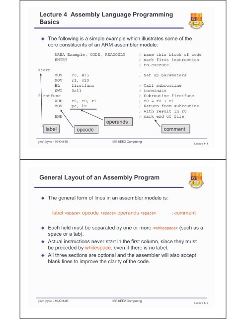
The following is a simple example which illustrates some of the<br />
<br />
core constituents of an ARM assembler module:<br />
label<br />
opcode<br />
operands<br />
comment<br />
gac1/pykc - 10-Oct-03<br />
ISE1/EE2 Computing<br />
<strong>Lecture</strong> 4- 1<br />
<strong>General</strong> <strong>Layout</strong> of an <strong>Assembly</strong> Program<br />
The general form of lines in an assembler module is:<br />
label opcode operands <br />
; comment<br />
Each field must be separated by one or more (such as a<br />
<br />
space or a tab).<br />
Actual instructions never start in the first column, since they must<br />
<br />
be preceded by whitespace, even if there is no label.<br />
All three sections are optional and the assembler will also accept<br />
<br />
blank lines to improve the clarity of the code.<br />
gac1/pykc - 10-Oct-03<br />
ISE1/EE2 Computing<br />
<strong>Lecture</strong> 4- 2
Description of Module<br />
The main routine of the program (labelled start ) loads the values<br />
<br />
15 and 20 into registers 0 and 1.<br />
The program then calls the subroutine firstfunc by using a branch<br />
<br />
with link instruction (BL).<br />
The subroutine adds together the two parameters it has received<br />
<br />
and places the result back into r0.<br />
It then returns by simply restoring the program counter to the<br />
<br />
address which was stored in the link register (r14) on entry.<br />
Upon return from the subroutine, the main program simply<br />
<br />
terminates using software interrupt (SWI) 11. This instructs the<br />
program to exit cleanly and return control to the debugger.<br />
gac1/pykc - 10-Oct-03<br />
ISE1/EE2 Computing<br />
<strong>Lecture</strong> 4- 3<br />
AREA, ENTRY & END <strong>Assembly</strong> Directives<br />
Directives are instructions to the assembler program, NOT to the<br />
<br />
microprocessor<br />
AREA Directive - specifies chunks of data or code that are<br />
<br />
manipulated by the linker.<br />
A complete application will consist of one or more areas. The example<br />
above consists of a single area which contains code and is marked as<br />
being read-only. A single CODE area is the minimum required to<br />
produce an application.<br />
ENTRY Directive - marks the first instruction to be executed within<br />
an application<br />
An application can contain only a single entry point and so in a multisource-module<br />
application, only a single module will contain an ENTRY<br />
<br />
directive.<br />
END directive - marks the end of the module<br />
<br />
gac1/pykc - 10-Oct-03<br />
ISE1/EE2 Computing<br />
<strong>Lecture</strong> 4- 4
Creating program and project file<br />
Invoke ARM_SDK program and enter the program as example1.s in<br />
<br />
the directory H:\arm_work\eg1\<br />
Use pulldown command >Project >New to create a new project<br />
<br />
called example1.apj<br />
Add all the files belonging to this project as shown (only one file<br />
<br />
here):<br />
gac1/pykc - 10-Oct-03<br />
ISE1/EE2 Computing<br />
<strong>Lecture</strong> 4- 5<br />
How to interpret the Project File (.apj)?<br />
This project has<br />
only one module:<br />
example1.s<br />
Options for assembler to build<br />
the project. The assembler<br />
produces an object file (.o) for<br />
the linker to use.<br />
Linker collects together all the assembled and<br />
compiled modules to form the .exe file<br />
gac1/pykc - 10-Oct-03<br />
ISE1/EE2 Computing<br />
<strong>Lecture</strong> 4- 6
Build and Run the program<br />
After building the<br />
<br />
project, you can invoke<br />
the debugger program<br />
and step through each<br />
instructions one at a<br />
time.<br />
The debugger program<br />
<br />
allows you to control the<br />
execution while viewing<br />
any register and<br />
memory location.<br />
You can also set<br />
<br />
breakpoints in the<br />
program.<br />
gac1/pykc - 10-Oct-03<br />
ISE1/EE2 Computing<br />
<strong>Lecture</strong> 4- 7<br />
Data Processing Instructions<br />
Three types of instructions:<br />
<br />
Data Processing<br />
<br />
Data Movement<br />
<br />
Control Flow <br />
Rules apply to ARM data processing instructions:<br />
<br />
All operands are 32 bits, come either from registers or are specified as<br />
<br />
constants (called literals) in the instruction itself<br />
The result is also 32 bits and is placed in a register<br />
<br />
3 operands - 2 for inputs and 1 for result<br />
<br />
Example: <br />
ADD r0, r1, r2 ; r0 := r1 + r2<br />
Works for both unsigned and 2's complement signed<br />
<br />
This may produce carry out signal and overflow bits, but ignored by<br />
<br />
default<br />
Result register can be the same as an input operand register<br />
<br />
gac1/pykc - 10-Oct-03<br />
ISE1/EE2 Computing<br />
<strong>Lecture</strong> 4- 8
Data Processing Instructions - Arithmetic<br />
operations<br />
ADD r0, r0, r1, r1, r2 r2 ;; r0 r0 := := r1 r1 + r2 r2<br />
ADC r0, r0, r1, r1, r2 r2 ;; r0 r0 := := r1 r1 + r2 r2 + C<br />
SUB SUB r0, r0, r1, r1, r2 r2 ;; r0 r0 := := r1 r1 --r2<br />
r2<br />
SBC SBC r0, r0, r1, r1, r2 r2 ;; r0 r0 := := r1 r1 --r2 r2 + C --1<br />
RSB RSB r0, r0, r1, r1, r2 r2 ;; r0 r0 := := r2 r2 --r1<br />
r1<br />
RSC RSC r0, r0, r1, r1, r2 r2 ;; r0 r0 := := r2 r2 --r1 r1 + C --1<br />
Here are ARM's arithmetic operations:<br />
RSB stands for reverse subtraction<br />
<br />
Operands may be unsigned or 2's complement signed integers<br />
<br />
'C' is the carry (C) bit in the CPSR - Current Program Status Reg<br />
<br />
ADC, SBC, and RSC are used to operate on data more than 32<br />
<br />
bits long in 32-bit chunks<br />
gac1/pykc - 10-Oct-03<br />
ISE1/EE2 Computing<br />
<strong>Lecture</strong> 4- 9<br />
ADC, SBC, RSC<br />
For example, let’s add two 64-bit numbers X and Y, storing the<br />
<br />
result in Z<br />
We need two registers per number<br />
<br />
store X is r1:r0, Y in r3:r2, and Z in r5:r4 (notation – MSW:LSW)<br />
<br />
ADDS<br />
ADC<br />
r4, r0, r2<br />
r5, r1, r3<br />
Then:<br />
“S” at the end of an instruction means you want to keep a record of<br />
<br />
the status of this operation in the C, V, N, and Z flags in the CPSR<br />
(lots more on this later)<br />
Similarly, if we wanted to subtract the two numbers:<br />
<br />
SUBS r4, r0, r2<br />
SBC r5, r1, r3<br />
gac1/pykc - 10-Oct-03<br />
ISE1/EE2 Computing<br />
<strong>Lecture</strong> 4- 10
ADC, SBC, RSC<br />
Some of you are probably thinking “why + C – 1”?!<br />
<br />
Remember that subtraction is performed by using two’s<br />
<br />
complement addition – for X-Y:<br />
find the two’s complement of Y<br />
<br />
add this value to X<br />
<br />
significant word<br />
Finding the two’s complement involves inverting all bits, adding 1<br />
<br />
You only want to add one to the least significant bit in the least<br />
<br />
So for all following words, this “added 1” needs to be subtracted off<br />
In practice, you will rarely want to use arithmetic on more than 32-<br />
<br />
bits<br />
gac1/pykc - 10-Oct-03<br />
ISE1/EE2 Computing<br />
<strong>Lecture</strong> 4- 11<br />
Data Processing Instructions - Logical operations<br />
Here are ARM's bit-wise logical operations:<br />
AND r0, r0, r1, r1, r2 r2 ;; r0 r0 := := r1 r1 and and r2 r2 (bit-by-bit for for 32 32 bits) bits)<br />
ORR r0, r0, r1, r1, r2 r2 ;; r0 r0 := := r1 r1 or or r2 r2<br />
EOR r0, r0, r1, r1, r2 r2 ;; r0 r0 := := r1 r1xor xorr2<br />
r2<br />
BIC BIC r0, r0, r1, r1, r2 r2 ;; r0 r0 := := r1 r1 and and not not r2 r2<br />
BIC stands for 'bit clear', where every '1' in the second operand<br />
<br />
clears the corresponding bit in the first:<br />
r1: 0101 0011 1010 1111 1101 1010 0110 1011<br />
r2: 1111 1111 1111 1111 0000 0000 0000 0000<br />
r0: 0000 0000 0000 0000 1101 1010 0110 1011<br />
gac1/pykc - 10-Oct-03<br />
ISE1/EE2 Computing<br />
<strong>Lecture</strong> 4- 12
Data Processing Instructions - Register Moves<br />
Here are ARM's register move operations:<br />
MOV r0, r0, r2 r2 ;; r0 r0 := := r2 r2<br />
MVN r0, r0, r2 r2 ;; r0 r0 := := not not r2 r2<br />
MVN stands for 'move negated'<br />
r2: 0101 0011 1010 1111 1101 1010 0110 1011<br />
r0: 1010 1100 0101 0000 0010 0101 1001 0100<br />
gac1/pykc - 10-Oct-03<br />
ISE1/EE2 Computing<br />
<strong>Lecture</strong> 4- 13<br />
Data Processing Instructions - Comparison<br />
Operations<br />
Here are ARM's register comparison operations:<br />
CMP r1, r1, r2 r2 ;; set set cc cc on on r1 r1 --r2<br />
r2<br />
CMN r1, r1, r2 r2 ;; set set cc cc on on r1 r1 + r2 r2<br />
TST TST r1, r1, r2 r2 ;; set set cc cc on on r1 r1 and and r2 r2<br />
TEQ TEQ r1, r1, r2 r2 ;; set set cc cc on on r1 r1xor xorr2<br />
r2<br />
Results of subtract, add, and, xor are NOT stored in any registers<br />
<br />
Only the condition code bits (cc) in the CPSR are set or cleared by these<br />
<br />
instructions (you don’t need the “S”)<br />
Take CMP r1,r2 instruction:<br />
<br />
N = 1 if MSB of (r1 - r2) is '1'<br />
<br />
Z = 1 if (r1 - r2) = 0<br />
<br />
C = 1 if carry-out of addition is 1<br />
<br />
V = 1 if carry-out of addition is different to carry-in to previous stage<br />
<br />
gac1/pykc - 10-Oct-03<br />
ISE1/EE2 Computing<br />
<strong>Lecture</strong> 4- 14
Data Transfer Instructions - single register<br />
load/store instructions<br />
Three basic forms of data transfer instructions:<br />
<br />
Single register load/store instructions<br />
<br />
Multiple register load/store instructions<br />
<br />
Single register swap instructions (combined load and store)<br />
<br />
Use a value in one register (called the base register) as a memory<br />
address and either loads the data value from that address into a<br />
destination register or stores the register value to memory:<br />
LDR r0, [r1] ; r0 := mem 32 [r1]<br />
STR r0, [r1] ; mem 32 [r1] := r0<br />
This is called register-indirect addressing<br />
<br />
LDR r0, [r1]<br />
<br />
memory<br />
r0<br />
DDDD DDDD<br />
r1<br />
AAAA AAAA<br />
AAAA AAAA<br />
DDDD DDDD<br />
gac1/pykc - 10-Oct-03<br />
ISE1/EE2 Computing<br />
<strong>Lecture</strong> 4- 15<br />
Data Transfer Instructions - Set up the address<br />
pointer<br />
Need to initialize address in r1 in the first place. How?<br />
<br />
Use ADR pseudo instruction - looks like normal instruction, but it is<br />
<br />
actually an assembler directive. The assembler translates it to one<br />
or more real instructions.<br />
The following example copies data from TABLE 1 to TABLE2<br />
copy copy ADR ADR r1, r1, TABLE1 ;; r1 r1 points points to to TABLE1<br />
ADR ADR r2, r2, TABLE2 ;; r2 r2 points points to to TABLE2<br />
LDR LDR r0, r0, [r1] [r1] ;; load load first first value value …. ….<br />
STR STR r0, r0, [r2] [r2] ;; and and store store it it in in TABLE2<br />
……. …….<br />
TABLE1 …… …… ;; data><br />
…… ……<br />
TABLE2 …… …… ;; data><br />
gac1/pykc - 10-Oct-03<br />
ISE1/EE2 Computing<br />
<strong>Lecture</strong> 4- 16
Data Transfer Instructions - ADR instruction<br />
pseudo<br />
instructions<br />
real<br />
instructions<br />
0000 8000<br />
0000 8004<br />
0000 8090<br />
0000 809C<br />
ADR r1,table1<br />
ADR r2,table2<br />
..........<br />
xxxxx<br />
..........<br />
yyyyy<br />
..........<br />
ADD r1, pc, #0x88<br />
ADD r2, pc, #0x90<br />
How does the ADR directive work? Address is 32-bit, difficult to put<br />
a 32-bit address value in a register in the first place<br />
Solution: Program Counter PC (r15) is often close to the desired<br />
data address value<br />
ADR r1, TABLE1 is translated into an instruction that adds or<br />
<br />
subtracts a constant to PC (r15), and puts the result in r1<br />
This constant is known as PC-relative offset, and it is calculated<br />
<br />
as: addr_of_table1 - (PC_value + 8)<br />
gac1/pykc - 10-Oct-03<br />
ISE1/EE2 Computing<br />
<strong>Lecture</strong> 4- 17<br />
Data Transfer Instructions - Base plus offset<br />
addressing<br />
Extend the copy program further to copy NEXT word:<br />
copy copy ADR ADR r1, r1, TABLE1 ;; r1 r1 points points to to TABLE1<br />
ADR ADR r2, r2, TABLE2 ;; r2 r2 points points to to TABLE2<br />
LDR LDR r0, r0, [r1] [r1] ;; load load first first value value …. ….<br />
STR STR r0, r0, [r2] [r2] ;; and and store store it it in in TABLE2<br />
ADD ADD r1, r1, r1, r1, #4 #4 ;; step step r1 r1 onto onto next next word word<br />
ADD ADD r2, r2, r2, r2, #4 #4 ;; step step r2 r2 onto onto next next word word<br />
LDR LDR r0, r0, [r1] [r1] ;; load load second value value …<br />
STR STR r0, r0, [r2] [r2] ;; and and store store it it<br />
…... …...<br />
Simplify with pre-indexed addressing mode<br />
<br />
LDR r0, [r1, #4] ; r0 := mem 32 [r1 + 4]<br />
base<br />
address<br />
offset<br />
effective<br />
address<br />
gac1/pykc - 10-Oct-03<br />
ISE1/EE2 Computing<br />
<strong>Lecture</strong> 4- 18
Data Transfer Instructions - pre-indexed with<br />
auto-indexing<br />
A simplified version is:<br />
copy copy ADR ADR r1, r1, TABLE1 ;; r1 r1 points points to to TABLE1<br />
ADR ADR r2, r2, TABLE2 ;; r2 r2 points points to to TABLE2<br />
LDR LDR r0, r0, [r1] [r1] ;; load load first first value value …. ….<br />
STR STR r0, r0, [r2] [r2] ;; and and store store it it in in TABLE2<br />
LDR LDR r0, r0, [r1, [r1,#4] ;; load load second value value …<br />
STR STR r0, r0, [r2, [r2,#4] ;; and and store store it it<br />
…... …...<br />
Pre-indexed addressing does not change r1. Sometimes, it is<br />
useful to modify the base register to point to the new address. This<br />
is achieve by adding a '!', and is pre-indexed addressing with autoindexing:<br />
LDR LDR r0, r0, [r1, [r1,#4]! ;; r0 r0 :: = mem 32 [r1<br />
32 [r1 + 4] 4]<br />
;; r1 r1 := := r1 r1 + 4<br />
The '!' indicates that the instruction should update the base register<br />
<br />
after the data transfer<br />
gac1/pykc - 10-Oct-03<br />
ISE1/EE2 Computing<br />
<strong>Lecture</strong> 4- 19<br />
Data Transfer Instructions - post-indexed<br />
addressing<br />
Another useful form of the instruction is:<br />
<br />
LDR LDR r0, r0, [r1], [r1],#4 #4 ;; r0 r0 :: = mem 32 [r1]<br />
32 [r1]<br />
;; r1 r1 := := r1 r1 + 4<br />
This is called: post-indexed addressing - the base address is used<br />
<br />
without an offset as the transfer address, after which it is always<br />
modified.<br />
Using this, we can improve the copy program more:<br />
copy copy ADR ADR r1, r1, TABLE1 ;; r1 r1 points points to to TABLE1<br />
ADR ADR r2, r2, TABLE2 ;; r2 r2 points points to to TABLE2<br />
loop loop LDR LDR r0, r0, [r1], [r1],#4 #4 ;; get get TABLE1 1st 1st word word …. ….<br />
STR STR r0, r0, [r2], [r2],#4 #4 ;; copy copy it it to to TABLE2<br />
??? ??? ;; if if more, more, go go back back to to loop loop<br />
…… ……<br />
TABLE1 …… …… ;; < source source of of data data ><br />
gac1/pykc - 10-Oct-03<br />
ISE1/EE2 Computing<br />
<strong>Lecture</strong> 4- 20
Data Transfer Instructions Summary<br />
Size of data can be reduced to 8-bit byte with:<br />
LDRB r0, r0, [r1] [r1] ;; r0 r0 :: = mem 8 [r1]<br />
8 [r1]<br />
Summary of addressing modes:<br />
LDR LDR r0, r0, [r1] [r1] ;; register-indirect addressing<br />
LDR LDR r0, r0, [r1 [r1,,# offset] offset] ;; pre-indexed addressing<br />
LDR LDR r0, r0, [r1 [r1,,# offset]! ;; pre-indexed, auto-indexing<br />
LDR LDR r0, r0, [r1], [r1],# offset offset ;; post-indexed, auto-indexing<br />
ADR ADR r0, r0, address_label ;; PC PC relative addressing<br />
gac1/pykc - 10-Oct-03<br />
ISE1/EE2 Computing<br />
<strong>Lecture</strong> 4- 21