Linear Slot Diffuser - Halton
Linear Slot Diffuser - Halton
Linear Slot Diffuser - Halton

Create successful ePaper yourself
Turn your PDF publications into a flip-book with our unique Google optimized e-Paper software.
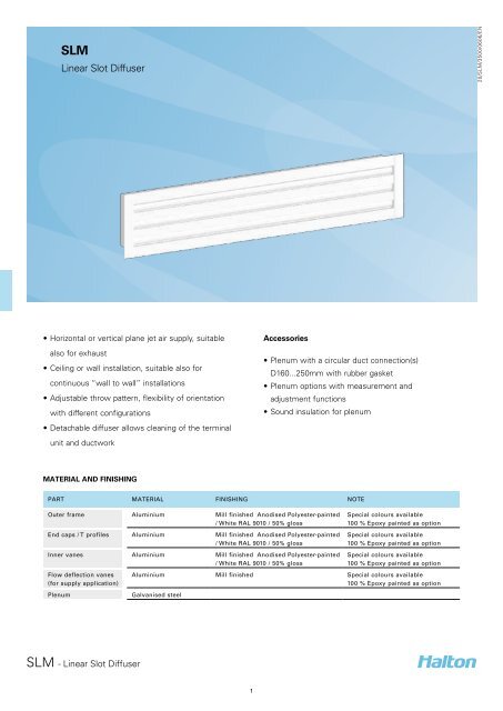
SLM<br />
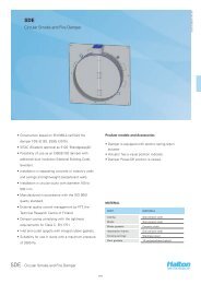
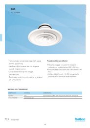
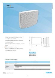
<strong>Linear</strong> <strong>Slot</strong> <strong>Diffuser</strong><br />
20/SLM/3500/0606/EN<br />
• Horizontal or vertical plane jet air supply, suitable<br />
also for exhaust<br />
• Ceiling or wall installation, suitable also for<br />
continuous “wall to wall” installations<br />
• Adjustable throw pattern, flexibility of orientation<br />
with different configurations<br />
• Detachable diffuser allows cleaning of the terminal<br />
unit and ductwork<br />
Accessories<br />
• Plenum with a circular duct connection(s)<br />
D160...250mm with rubber gasket<br />
• Plenum options with measurement and<br />
adjustment functions<br />
• Sound insulation for plenum<br />
MATERIAL AND FINISHING<br />
PART MATERIAL FINISHING NOTE<br />
Outer frame Aluminium Mill finished Anodised Polyester-painted<br />
/ White RAL 9010 / 50% gloss<br />
End caps / T profiles Aluminium Mill finished Anodised Polyester-painted<br />
/ White RAL 9010 / 50% gloss<br />
Inner vanes Aluminium Mill finished Anodised Polyester-painted<br />
/ White RAL 9010 / 50% gloss<br />
Flow deflection vanes<br />
(for supply application)<br />
Plenum<br />
Special colours available<br />
100 % Epoxy painted as option<br />
Special colours available<br />
100 % Epoxy painted as option<br />
Special colours available<br />
100 % Epoxy painted as option<br />
Aluminium Mill finished Special colours available<br />
100 % Epoxy painted as option<br />
Galvanised steel<br />
SLM - <strong>Linear</strong> <strong>Slot</strong> <strong>Diffuser</strong><br />
1
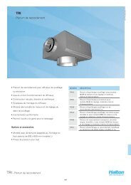
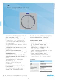
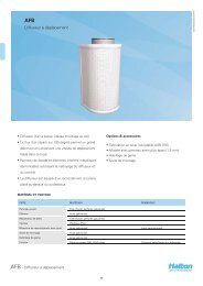
DIMENSIONS<br />
SLM<br />
32<br />
SLM + PLM<br />
L1<br />
K2<br />
20/SLM/3500/0606/EN<br />
25<br />
L<br />
K<br />
H<br />
H1<br />
ØD<br />
L1<br />
K1<br />
75<br />
L<br />
K<br />
Standard dimensions of SLM + PLM plenum unit with<br />
standard end caps are presented in the table below.<br />
Active length <strong>Slot</strong>s L L1 H H1 K K1 K2 ØD<br />
572 1 636 570 275..295 200 90 59 130 1x160<br />
872 1 936 870 275..295 200 90 59 130 1x160<br />
1172 1 1236 1170 275..295 200 90 59 130 1x160<br />
1472 1 1536 1470 275..295 200 90 59 130 2x160<br />
1772 1 1836 1770 275..295 200 90 59 130 2x160<br />
572 2 636 570 315..335 240 141 109 181 1x200<br />
872 2 936 870 315..335 240 141 109 181 1x200<br />
1172 2 1236 1170 315..335 240 141 109 181 1x200<br />
1472 2 1536 1470 315..335 240 141 109 181 2x200<br />
1772 2 1836 1770 315..335 240 141 109 181 2x200<br />
572 3 636 570 365..385 290 192 160 232 1x200<br />
872 3 936 870 365..385 290 192 160 232 1x200<br />
1172 3 1236 1170 365..385 290 192 160 232 1x200<br />
1472 3 1536 1470 365..385 290 192 160 232 2x200<br />
1772 3 1836 1770 365..385 290 192 160 232 2x200<br />
572 4 636 570 365..385 290 243 211 283 1x250<br />
872 4 936 870 365..385 290 243 211 283 1x250<br />
1172 4 1236 1170 365..385 290 243 211 283 1x250<br />
1472 4 1536 1470 365..385 290 243 211 283 2x250<br />
1772 4 1836 1770 365..385 290 243 211 283 2x250<br />
The width of the end caps is 32 mm.<br />
Special dimensions<br />
In addition to standard sizes, other sizes can be<br />
specially ordered. The maximum length is 2 400 mm.<br />
Continuous linear diffusers with modular construction<br />
are available for diffuser lengths greater than 2400<br />
mm. The diffuser modules are delivered with<br />
alignment strips.<br />
SLM - <strong>Linear</strong> <strong>Slot</strong> <strong>Diffuser</strong><br />
2
20/SLM/3500/0606/EN<br />
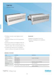
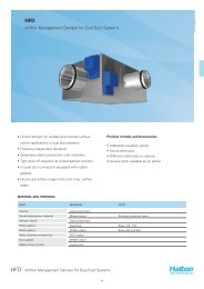
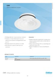
Function<br />
Air is supplied through the linear slots of the diffuser,<br />
either horizontally along the ceiling surface or vertically<br />
into the occupied zone.<br />
For wall installations, the plane jet air is supplied either<br />
horizontally or directed to the ceiling surface, thus<br />
increasing the throw length.<br />
Installation<br />
The SLM linear slot diffuser is connected directly to<br />
the PLM or PLD plenum.<br />
The plenum is installed into the suspended ceiling<br />
with M8 drop rods (not included in the delivery) and<br />
connected to the ductwork.<br />
Remove the T-profiles of the SLM by pulling them<br />
gently out, in order to access the transversal bars<br />
located behind the profiles.<br />
Fit the installation brackets into the grooves of the<br />
plenum and secure fixing with the screws supplied<br />
with the unit.<br />
Put screws into the holes of the transversal bars.<br />
Screw on until the diffuser is flush to the ceiling.<br />
Replace the T-profiles.<br />
The unit can be installed in a suspended ceiling by<br />
using the end caps N2 with a 32 mm flange.<br />
The unit can be used for exhaust air by connecting<br />
the unit (model SLM/E) to the exhaust ceiling plenum<br />
using ST installation brackets.<br />
ACCESSORIES<br />
ACCESSORY CODE DESCRIPTION<br />
Plenum PLM Plenum for duct connection (with or without attenuation material)<br />
Plenum PLD Compact plenum for duct connection (with or without attenuation material)<br />
Airflow measurement and<br />
adjustment module<br />
Airflow measurement and<br />
adjustment module<br />
MSM<br />
MEM<br />
For supply installation<br />
For exhaust installation<br />
End caps N2 For modular ceiling. Width = 32 mm (2 pcs)<br />
Sound attenuation IN Mineral wool<br />
Installation brackets ST For installation of exhaust model (SLM/E) into the exhaust ceiling plenum<br />
Special end caps are available for modular ceilings.<br />
SLM - <strong>Linear</strong> <strong>Slot</strong> <strong>Diffuser</strong><br />
3
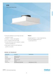
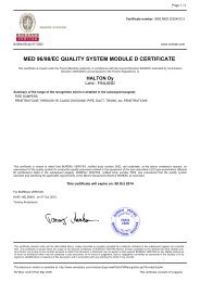
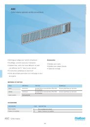
Adjustment<br />
The air pattern can be changed through 180° by<br />
adjusting (use a screw driver) the flow deflection<br />
vanes. Each deflection vane section can be individually<br />
adjusted without removing the T-profiles, in order to<br />
provide flexibility in supply air pattern orientation.<br />
<strong>Diffuser</strong>s are delivered unadjusted with the flow<br />
deflection vanes in the open position.<br />
In order to enable airflow adjustment and<br />
measurement of airflow rate, it is recommended<br />
that the diffuser be connected to the PLM or PLD<br />
balancing plenum equipped with the MSM module in<br />
supply and MEM in exhaust.<br />
The supply flow rate is determined by using the<br />
measurement and adjustment module MSM.<br />
Detach the linear diffuser and pass the tubes and<br />
control spindle through the linear diffuser between the<br />
flow deflection vanes.<br />
Replace the diffuser.<br />
Measure the differential pressure using a manometer.<br />
The airflow rate is calculated using the formula below.<br />
Servicing<br />
Remove the T-profiles.<br />
Remove the linear diffuser by unscrewing the screws<br />
of the transversal bars.<br />
Clean the parts by wiping them with a damp cloth.<br />
Push the linear diffuser back into place by screwing<br />
the transversal bars to the installation brackets.<br />
Option: with balancing plenum PLM + MSM/MEM<br />
or PLD + MSM/MEM<br />
Remove the measurement and adjustment module<br />
by gently pulling the shaft; (not the control spindle or<br />
measurement tubes!).<br />
Wipe the parts with a damp cloth, instead of<br />
immersing in water.<br />
Reassemble the measurement and adjustment<br />
module by pushing the shaft back into place until the<br />
module meets the stopper.<br />
Push the linear diffuser back into place by screwing<br />
the transversal bars to the installation brackets.<br />
20/SLM/3500/0606/EN<br />
q<br />
v<br />
= k *<br />
∆p<br />
m<br />
Adjust the airflow rate by rotating the control spindle<br />
until the desired setting is achieved.<br />
Lock the damper position with a screw.<br />
Replace the tubes and spindle into the plenum and<br />
replace the linear diffuser.<br />
SLM - <strong>Linear</strong> <strong>Slot</strong> <strong>Diffuser</strong><br />
4
Suggested specifications<br />
The linear slot diffuser shall have an extruded<br />
aluminium outer frame, flow deflection vanes and<br />
T-profiles, anodised or polyester-painted to white (RAL<br />
9010) colour. Each air pattern adjustment section shall<br />
comprise two flow deflection vanes.<br />
Product code<br />
SLM/S-N-L<br />
S = Model<br />
S<br />
E<br />
Supply<br />
Exhaust<br />
20/SLM/3500/0606/EN<br />
The diffuser shall be connected to the ductwork using<br />
a plenum with mineral wool as sound attenuation<br />
material.<br />
The removable linear slot diffuser shall be mounted<br />
into the plenum with invisible screws.<br />
N = Number of slots<br />
1, 2, 3, 4<br />
L = Length<br />
400,+1,..,50000<br />
The plenum shall comprise an airflow measurement<br />
and adjustment module. The linear diffuser shall<br />
be removable in order to provide access to the<br />
measurement and adjustment module in the plenum.<br />
Flow deflection vanes and T-profiles shall be easily<br />
removable for access to the plenum.<br />
The supply air pattern shall be directable by adjusting<br />
the flow deflection vanes without any change in the<br />
appearance of the diffuser.<br />
Specifics and accessories<br />
SE = End caps (Y/N)<br />
Y Yes<br />
N No<br />
ST = Type of end caps<br />
NA Not assigned<br />
N2 Standard 32 mm<br />
FI = Finishing<br />
AN Anodised (class 10 um)<br />
PN Painted<br />
MF Mill finished<br />
CO = Colour<br />
W<br />
X<br />
N<br />
White<br />
Special colour<br />
No painting<br />
Code example<br />
SLM/S-1-400, SE=Y,ST=N2,FI=AN,CO=N<br />
Sub products<br />
PLL<br />
Plenum (<strong>Linear</strong> slot diffusers)<br />
SLM - <strong>Linear</strong> <strong>Slot</strong> <strong>Diffuser</strong><br />
5