Air-cooled chiller - McQuay
Air-cooled chiller - McQuay
Air-cooled chiller - McQuay

You also want an ePaper? Increase the reach of your titles
YUMPU automatically turns print PDFs into web optimized ePapers that Google loves.
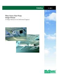
Installation, maintenance and operating Manual<br />
507 C – 06/01 A<br />
<br />
Date: January 2006<br />
Supersedes: none<br />
<br />
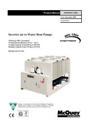
<strong>Air</strong>-<strong>cooled</strong> <strong>chiller</strong><br />
With screw compressor<br />
<br />
McEnergy<br />
SE 052.2÷105.2<br />
ClassA 069.2÷114.2<br />
HA 052.2÷105.2<br />
50Hz – Refrigerant: HFC 134a
Index<br />
General Information .......................................................................................................................................................... 4<br />
Receiving the machine ................................................................................................................................................... 4<br />
Checks ........................................................................................................................................................................... 4<br />
Purpose of this Manual................................................................................................................................................... 4<br />
Nomenclature ................................................................................................................................................................. 4<br />
Mechanical Installation................................................................................................................................................... 11<br />
Shipping ....................................................................................................................................................................... 11<br />
Responsibility ............................................................................................................................................................... 11<br />
Safety ........................................................................................................................................................................... 11<br />
Attention ....................................................................................................................................................................... 11<br />
Moving and lifting ......................................................................................................................................................... 12<br />
Positioning and assembly............................................................................................................................................. 13<br />
Minimum space requirements ...................................................................................................................................... 13<br />
Sound protection .......................................................................................................................................................... 15<br />
Water piping ................................................................................................................................................................. 15<br />
Water treatment............................................................................................................................................................ 16<br />
Evaporator and recovery exchangers anti-freeze protection ........................................................................................ 16<br />
Installing the flow switch............................................................................................................................................... 18<br />
Hydronic kit (optional)................................................................................................................................................... 19<br />
Refrigerating circuit safety valves................................................................................................................................. 20<br />
Electrical installation ...................................................................................................................................................... 26<br />
General specifications .................................................................................................................................................. 26<br />
Electrical components .................................................................................................................................................. 29<br />
Electrical wiring ............................................................................................................................................................ 29<br />
Electrical resistances.................................................................................................................................................... 29<br />
Electrical power supply to the pumps ........................................................................................................................... 29<br />
Water pump control ...................................................................................................................................................... 29<br />
Unit On/ Off remote control – Electrical wiring.............................................................................................................. 30<br />
Double Setpoint – Electrical wiring ............................................................................................................................... 30<br />
External water Setpoint reset – Electrical wiring........................................................................................................... 30<br />
Unit limitation – Electrical wiring ................................................................................................................................... 30<br />
Operation ......................................................................................................................................................................... 32<br />
Operator’s responsibilities ............................................................................................................................................ 32<br />
Description of the machine........................................................................................................................................... 32<br />
Description of the chilling cycle .................................................................................................................................... 32<br />
Description of the chilling cycle with partial heat recovery............................................................................................ 37<br />
Controlling the partial recovery circuit and installation recommendations .................................................................... 37<br />
Description of chilling cycle operating with full heat recovery....................................................................................... 42<br />
Total heat recovery circuit control................................................................................................................................. 42<br />
Compressor.................................................................................................................................................................. 47<br />
Compression process................................................................................................................................................... 47<br />
Chilling capacity control................................................................................................................................................ 49<br />
Shutter valve control..................................................................................................................................................... 49<br />
Pre-startup checks.......................................................................................................................................................... 51<br />
General......................................................................................................................................................................... 51<br />
Units with an external water pump ............................................................................................................................... 52<br />
Units with a built-in water pump.................................................................................................................................... 52<br />
Electrical power supply................................................................................................................................................. 52<br />
Unbalance in power supply voltage.............................................................................................................................. 53<br />
Electrical resistances power supply.............................................................................................................................. 53<br />
Startup procedure ........................................................................................................................................................... 54<br />
Turning on the machine................................................................................................................................................ 54<br />
Seasonal shutdown ...................................................................................................................................................... 55<br />
Starting up after seasonal shutdown ............................................................................................................................ 55<br />
System maintenance....................................................................................................................................................... 56<br />
General......................................................................................................................................................................... 56<br />
Compressor maintenance ............................................................................................................................................ 56<br />
Lubrication.................................................................................................................................................................... 56<br />
Routine maintenance.................................................................................................................................................... 57<br />
Dehydration filter replacement...................................................................................................................................... 58<br />
Dehydration filter cartridge replacement procedure...................................................................................................... 58<br />
Oil filter replacement..................................................................................................................................................... 59<br />
Oil filter replacement procedure ................................................................................................................................... 59<br />
Refrigerant charge........................................................................................................................................................ 61<br />
Refrigerant replenishment procedure ........................................................................................................................... 62
Standard Checks............................................................................................................................................................. 63<br />
Sensori di temperatura e pressione.............................................................................................................................. 63<br />
Test sheet ........................................................................................................................................................................ 64<br />
Water side measurements............................................................................................................................................ 64<br />
Refrigerant side measurements ................................................................................................................................... 64<br />
Electrical measurements .............................................................................................................................................. 64<br />
Service and limited warranty.......................................................................................................................................... 65<br />
Index of tables<br />
<br />
Table 1- McEnergy SE LN - HFC 134a Technical Data ...................................................................................................... 5<br />
Table 2 - McEnergy SE XN - HFC 134°Technical Data ..................................................................................................... 6<br />
Table 3 - McEnergy SE XXN - HFC 134°Technical Data ................................................................................................... 7<br />
Table 4 - McEnergy ClassA ST - HFC 134a Technical Data............................................................................................... 8<br />
Table 5 - McEnergy ClassA XN - HFC 134°Technical Data............................................................................................... 9<br />
Table 6 - McEnergy HA ST - HFC 134°Technical Data.................................................................................................... 10<br />
Table 7 – Acceptable water quality limits .......................................................................................................................... 16<br />
Table 8 – Electrical Data McEnergy Series SE Unit.......................................................................................................... 27<br />
Table 9 – Electrical Data McEnergy Unit Class A and HA Series ..................................................................................... 28<br />
Table 10 – Electrical data for optional pumps ................................................................................................................... 29<br />
Table 11 – Typical working conditions with compressors at 100%.................................................................................... 54<br />
Table 12 – Routine maintenance programme ................................................................................................................... 57<br />
Table 13 – Pressure/ Temperature ................................................................................................................................... 62
General Information<br />
Receiving the machine<br />
The machine must be inspected for any possible damage immediately upon reaching its final place of installation. All<br />
components described in the delivery note must be carefully verified and checked; any damage must be reported to the<br />
transporter. Check on the machine nameplate, before connecting it to earth, that the model and power supply voltage are<br />
as ordered. Responsibility for any damage after acceptance of the machine cannot be attributed to <strong>McQuay</strong> Italia Spa.<br />
Checks<br />
Please perform the following checks upon receipt of the machine, for your protection in the event that it is incomplete<br />
(any missing parts) or has incurred damage during transport:<br />
a) Before accepting the machine, please verify every single component in the consignment. Check for any<br />
damage.<br />
b) In the event that the machine has been damaged, do not remove the damaged material. A set of photographs<br />
are helpful in ascertaining responsibility.<br />
c) Immediately report the extent of the damage to the trasnporter and immediately request that they inspect the<br />
machine.<br />
d) Immediately report the extent of the damage to the McQUay representative, so that arrangements can be made<br />
for the required repairs. In no case must the damage be repaired before the machine has been inspected by the<br />
representative of the transportation company.<br />
<br />
Purpose of this Manual<br />
The purpose of this Manual is to allow the installer and the qualified operator to carry out all required operations in order<br />
to ensure proper installation and maintenance of the machine, without risking any damage to people, animals and/or<br />
objects.<br />
This Manual is an important supporting document for qualified personnel but it is not intended to replace such<br />
personnel. All activities must be carried out in compliance with local laws and regulations.<br />
Nomenclature<br />
McEnergy SE 070 .2 LN 134<br />
McEnergy<br />
SE<br />
A<br />
Screw unit<br />
Standard Efficiency<br />
High Efficiency<br />
060 090 Size of Unit<br />
2 Number of Compressors<br />
LN<br />
Standard Version<br />
XN Silenced Version<br />
XXN Ultrasilenced Version<br />
134 HFC 134a Refrigerant<br />
Figure 1 - Nomenclature
Table 1- McEnergy SE LN - HFC 134a Technical Data<br />
Size of Unit 052.2 056.2 064.2 070.2 074.2<br />
<strong>McQuay</strong> Screw Compressor N. 2 2 2 2 2<br />
Refrigerant circuits N. 2 2 2 2 2<br />
HFC 134°Refrigerant Charge kg 44 60 60 60 70<br />
Oil Charge kg 26 26 26 26 26<br />
Condenser Ventilators<br />
No. of ventilators / Nominal ventilator power N. / kW 4/1,16 4/1,16 6/1,16 6/1,16 6/1,16<br />
Rotation speed rpm 900 900 900 900 900<br />
Diameter mm 710 710 710 710 710<br />
Total air flow rate m 3 /s 15,3 14,9 22,9 22,9 22,6<br />
Evaporator<br />
Evaporator / Water volume N. / l 1/25 1/31 1/93 1/93 1/90<br />
Maximum design pressure (water-side) bars 10,5 10,5 10,5 10,5 10,5<br />
Diameter of water joints Inches 3 3 4 4 4<br />
Condenser Batteries<br />
Type of fin<br />
Weights and dimensions<br />
Lanced fins – Internally spiral wound tubes<br />
Shipping weight of standard unit kg 2380 2466 2766 2766 2806<br />
Operating weight standard unit kg 2405 2497 2859 2859 2896<br />
Length of Unit mm 2240 2240 3140 3140 3140<br />
Width of Unit mm 2235 2235 2235 2235 2235<br />
Height of Unit mm 2340 2340 2340 2340 2340<br />
Size of Unit 078.2 085.2 091.2 105.2<br />
<strong>McQuay</strong> Screw Compressor N. 2 2 2 2<br />
Refrigerant circuits N. 2 2 2 2<br />
HFC 134°Refrigerant charge kg 80 80 80 80<br />
Oil charge kg 26 26 26 26<br />
Condenser Ventilators<br />
No. of ventilators / Nominal ventilator power N. / kW 6 / 1,16 6 / 1,16 8 / 1,16 8 / 1,16<br />
Rotation speed rpm 900 900 900 900<br />
Diameter mm 710 710 710 710<br />
Total air flow rate m 3 /s 22,3 22,3 30,6 30,6<br />
Evaporator<br />
Evaporator / Water volume N. / l 1 / 90 1 / 90 1 / 113 1 / 113<br />
Maximum design pressure (water-side) bars 10,5 10,5 10,5 10,5<br />
Diameter of water joints Inches 4 4 4 4<br />
Condenser Batteries<br />
Type of fin<br />
Lanced fins – Internally spiral wound tubes<br />
Weights and dimensions<br />
Shipping weight of standard unit kg 2846 2846 3166 3186<br />
Operating weight of standard unit kg 2936 2936 3279 3299<br />
Length of Unit mm 3140 3140 4040 4040<br />
Width of Unit mm 2235 2235 2235 2235<br />
Height of Unit mm 2340 2340 2340 2340
Table 2 - McEnergy SE XN - HFC 134°Technical Data<br />
Size of Unit 052.2 056.2 064.2 070.2 074.2<br />
<strong>McQuay</strong> Screw Compressor N. 2 2 2 2 2<br />
Refrigerant Circuits N. 2 2 2 2 2<br />
HFC 134°Refrigerant Charge kg 44 60 60 60 70<br />
Oil Charge kg 26 26 26 26 26<br />
Condenser Ventilators<br />
No. of ventilators / Nominal ventilator power N. / kW 4/0,7 4/0,7 6/0,7 6/0,7 6/0,7<br />
Rotation Speed rpm 680 680 680 680 680<br />
Diameter mm 710 710 710 710 710<br />
Total air flow rate m 3 /s 12,4 11,9 18,6 18,6 18,2<br />
Evaporator<br />
Evaporator / Water volume N. / l 1/25 1/31 1/93 1/93 1/90<br />
Maximum design pressure (water-side) bars 10,5 10,5 10,5 10,5 10,5<br />
Diameter of water joints Inches 3 3 4 4 4<br />
Condenser batteries<br />
Type of fin<br />
Weights and Dimensions<br />
Lanced fins – Internally spiral wound tubes<br />
Shipping weight of standard unit kg 2530 2616 2916 2916 2956<br />
Operating weight of standard unit kg 2555 2647 3009 3009 3046<br />
Length of Unit mm 2240 2240 3140 3140 3140<br />
Width of Unit mm 2235 2235 2235 2235 2235<br />
Height of Unit mm 2340 2340 2340 2340 2340<br />
Size of Unit 078.2 085.2 091.2 105.2<br />
<strong>McQuay</strong> Screw Compressor N. 2 2 2 2<br />
Refrigerant Circuits N. 2 2 2 2<br />
HFC 134°Refrigerant Charge kg 80 80 80 80<br />
Oil Charge kg 26 26 26 26<br />
Condenser Ventilators<br />
No. of ventilators / Nominal ventilator power N. / kW 6/0,7 6/0,7 8/0,7 8/0,7<br />
Rotation speed rpm 680 680 680 680<br />
Diameter mm 710 710 710 710<br />
Total air flow rate m 3 /s 17,9 17,9 24,8 24,8<br />
Evaporator<br />
Evaporator / Water volume N. / l 1 / 90 1 / 90 1 / 113 1 / 113<br />
Maximum design pressure (water-side) bars 10,5 10,5 10,5 10,5<br />
Diameter of water connections Inches 4 4 4 4<br />
Condenser batteries<br />
Type of fin<br />
Lanced fins – Internally spiral wound tubes<br />
Weights and Dimensions<br />
Shipping weight of standard unit kg 2996 2996 3316 3336<br />
Operating weight of standard unit kg 3086 3086 3429 3449<br />
Unit length mm 3140 3140 4040 4040<br />
Unit width mm 2235 2235 2235 2235<br />
Unit height mm 2340 2340 2340 2340
Table 3 - McEnergy SE XXN - HFC 134°Technical Data<br />
Size of Unit 056.2 064.2 070.2 074.2<br />
<strong>McQuay</strong> Screw Compressor N. 2 2 2 2<br />
Refrigerant circuits N. 2 2 2 2<br />
HFC 134°Refrigerant charge kg 80 80 100 110<br />
Oil charge kg 26 26 26 26<br />
Condenser ventilators<br />
No. of ventilators / Nominal ventilator power N./kW 6/0,45 8/0,45 8/0,45 8/0,45<br />
Rotation speed rpm 500 500 500 500<br />
Diameter mm 710 710 710 710<br />
Total air flow rate m 3 /s 12,9 17,9 17,2 17,2<br />
Evaporator<br />
Evaporator / Water volume N./l 1/90 1/113 1/113 1/164<br />
Maximum design pressure (water-side) bars 10,5 10,5 10,5 10,5<br />
Diameter of water joints ’’ 4 4 4 4<br />
Condenser batteries<br />
Type of fin<br />
Weights and Sizes<br />
Lanced fins – Internally spiral wound tubes<br />
Shipping weight of standard unit kg 3046 3366 3466 3546<br />
Operating weight of standard unit kg 3136 3479 3579 3710<br />
Unit length mm 3140 4040 4040 4040<br />
Unit width mm 2235 2235 2235 2235<br />
Unit height mm 2340 2340 2340 2340<br />
Size of Unit 078.2 085.2 091.2<br />
<strong>McQuay</strong> Screw Compressor N. 2 2 2<br />
Refrigerant circuits N. 2 2 2<br />
HFC 134a Refrigerant charge kg 110 110 110<br />
Oil charge kg 26 26 26<br />
Condenser ventilators<br />
No. of ventilators / Nominal ventilator power N./kW 8/0,45 8/0,45 8/0,45<br />
Rotation speed rpm 500 500 500<br />
Diameter mm 710 710 710<br />
Total air flow rate m 3 /s 17,2 17,2 17,2<br />
Evaporator<br />
Evaporator / Water volume N./l 1/159 1/159 1/159<br />
Maximum design pressure (water-side) bars 10,5 10,5 10,5<br />
Diameter of water joints ’’ 4 4 4<br />
Condenser batteries<br />
Type of fin<br />
Lanced fins – Internally spiral wound tubes<br />
Weights and dimensions<br />
Shipping weight of standard unit kg 3556 3556 3556<br />
Operating weight of standard unit kg 3715 3715 3715<br />
Unit length mm 4040 4040 4040<br />
Unit width mm 2235 2235 2235<br />
Unit height mm 2340 2340 2340
Table 4 - McEnergy ClassA ST - HFC 134a Technical Data<br />
Size of Unit 069.2 077.2 084.2 092.2<br />
<strong>McQuay</strong> Screw Compressor N. 2 2 2 2<br />
Refrigerant circuits N. 2 2 2 2<br />
HFC 134°Refrigerant Charge kg 80 80 100 110<br />
Oil charge kg 26 26 26 26<br />
Condenser Ventilators<br />
No. of ventilators / Nominal ventilator power N. / kW 6/1,16 8/1,16 8/1,16 8/1,16<br />
Rotation speed rpm 900 900 900 900<br />
Diameter mm 710 710 710 710<br />
Total air flow m 3 /s 22,3 30,6 29,7 29,7<br />
Evaporator<br />
Evaporator / Water volume N. / l 1 / 93 1 / 113 1 / 113 1 / 164<br />
Maximum design pressure (water-side) bars 10,5 10,5 10,5 10,5<br />
Diameter of water joints ’’ 4 4 4 4<br />
Condenser batteries<br />
Type of fin<br />
Weights and dimensions<br />
Lanced fins – Internally spiral wound tubes<br />
Shipping weight of standard unit kg 2866 3186 3286 3366<br />
Operating weight of standard unit kg 2959 3299 3399 3530<br />
Unit length mm 3140 4040 4040 4040<br />
Unit width mm 2235 2235 2235 2235<br />
Unit height mm 2340 2340 2340 2340<br />
Unit size 100.2 106.2 114.2<br />
<strong>McQuay</strong> screw compressor N. 2 2 2<br />
Refrigerant circuits N. 2 2 2<br />
HFC 134°Refrigerant charge kg 110 95 110<br />
Oil charge kg 26 26 26<br />
Condenser ventilators<br />
No. of ventilators / Nominal ventilator power N./kW 8/1,16 8/1,80 8/1,80<br />
Rotation speed rpm 900 900 900<br />
Diameter mm 710 800 800<br />
Total air flow rate m 3 /s 29,7 44,0 43,0<br />
Evaporator<br />
Evaporator / Water volume N./l 1/159 1/159 1/159<br />
Maximum design pressure (water-side) bars 10,5 10,5 10,5<br />
Diameter of water joints ’’ 4 4 4<br />
Condenser batteries<br />
Type of fin<br />
Weights and dimensions<br />
Lanced fins – Internally spiral wound<br />
t b<br />
Shipping weight of standard unit kg 3376 3321 3386<br />
Operating weight of standard unit kg 3535 3480 3545<br />
Unit length mm 4040 4040 4040<br />
Unit width mm 2235 2235 2235<br />
Unit height mm 2340 2340 2340
Table 5 - McEnergy ClassA XN - HFC 134°Technical Data<br />
Unit Size 069.2 077.2 084.2 092.2<br />
<strong>McQuay</strong> Screw Compressor N. 2 2 2 2<br />
Refrigerant circuits N. 2 2 2 2<br />
HFC 134°Refrigerant charge kg 80 100 100 110<br />
Oil charge kg 26 26 26 26<br />
Condenser ventilators<br />
No. of ventilators / Nominal ventilator speed N. / kW 6/0,7 8/0,7 8/0,7 8/0,7<br />
Rotation speed rpm 680 680 680 680<br />
Diameter mm 710 710 710 710<br />
Total air flow rate m 3 /s 17,9 24,8 23,9 23,9<br />
Evaporator<br />
Evaporator / Water volume N. / l 1 / 93 1 / 113 1 / 113 1 / 164<br />
Maximum design pressure (water-side) bars 10,5 10,5 10,5 10,5<br />
Diameter of water joints ’’ 4 4 4 4<br />
Condenser batteries<br />
Type of fin<br />
Weights and dimensions<br />
Lanced fins – Internally spiral wound tubes<br />
Shipping weight of standard unit kg 3006 3346 3426 3516<br />
Operating weight of standard unit kg 3099 3459 3539 3680<br />
Unit length mm 3140 4040 4040 4040<br />
Unit width mm 2235 2235 2235 2235<br />
Unit height mm 2340 2340 2340 2340<br />
Size of Unit 100.2 106.2 114.2<br />
<strong>McQuay</strong> Screw Compressor N. 2 2 2<br />
Refrigerant circuits N. 2 2 2<br />
HFC 134°Refrigerant charge kg 110 95 110<br />
Oil charge kg 26 26 26<br />
Condenser ventilators<br />
No. of ventilators / Nominal ventilator power N. / kW 8/0,7 8/0,9 8/0,9<br />
Rotation speed rpm 680 700 700<br />
Diameter mm 710 800 800<br />
Total air flow rate m 3 /s 23,9 33,5 32,7<br />
Evaporator<br />
Evaporator / Water volume N. / l 1 / 159 1 / 159 1 / 159<br />
Maximum design pressure (water-side) bars 10,5 10,5 10,5<br />
Diameter of water joints ’’ 4 4 4<br />
Condenser batteries<br />
Type of fin<br />
Lanced fins – Internally spiral wound tubes<br />
Weights and dimensions<br />
Shipping weight of standard unit kg 3526 3471 3526<br />
Operating weight of standard unit kg 3685 3630 3685<br />
Unit length mm 4040 4040 4040<br />
Unit width mm 2235 2235 2235<br />
Unit height mm 2340 2340 2340
Table 6 - McEnergy HA ST - HFC 134°Technical Data<br />
Size of Unit 052.2 056.2 064.2 070.2 074.2<br />
<strong>McQuay</strong> Screw Compressor N. 2 2 2 2 2<br />
Refrigerant circuits N. 2 2 2 2 2<br />
HFC 134°Refrigerant Charge kg 44 60 60 60 70<br />
Oil charge kg 26 26 26 26 26<br />
Condenser ventilators<br />
No. of ventilators / Nominal ventilator power N./kW 4/1,80 4/1,80 6/1,80 6/1,80 6/1,80<br />
Rotation Sped rpm 900 900 900 900 900<br />
Diameter mm 800 800 800 800 800<br />
Total air flow m 3 /s 23,9 22,8 35,9 35,9 35,0<br />
Evaporator<br />
Evaporator / Water volume N./l 1 / 25 1 / 31 1 / 93 1 / 93 1 / 90<br />
Maximum design pressure (water-side) bars 10,5 10,5 10,5 10,5 10,5<br />
Diameter of water joints ’’ 3 3 4 4 4<br />
Condenser batteries<br />
Type of fin<br />
Weights and Dimensions<br />
Lanced fins – Internally spiral wound tubes<br />
Shipping weight of standard unit kg 2380 2466 2766 2766 2806<br />
Operating weight of standard unit kg 2405 2497 2859 2859 2896<br />
Unit length mm 2240 2240 3140 3140 3140<br />
Unit width mm 2235 2235 2235 2235 2235<br />
Unit height mm 2340 2340 2340 2340 2340<br />
Size of Unit 078.2 085.2 091.2 105.2<br />
<strong>McQuay</strong> Screw Compressor N. 2 2 2 2<br />
Refrigerant circuits N. 2 2 2 2<br />
HFC 134°Refrigerant Charge kg 80 80 80 80<br />
Oil charge kg 26 26 26 26<br />
Condenser ventilators<br />
No. of ventilators / Nominal ventilator power N./kW 6/1,80 6/1,80 8/1,80 8/1,80<br />
Rotation speed rpm 900 900 900 900<br />
Diameter mm 800 800 800 800<br />
Total air flow m 3 /s 34,1 34,1 47,9 47,9<br />
Evaporator<br />
Evaporator / Water volume N./l 1/90 1/90 1/113 1/113<br />
Maximum design pressure (water-side) bars 10,5 10,5 10,5 10,5<br />
Diameter of water joints ’’ 4 4 4 4<br />
Condenser batteries<br />
Type of fin<br />
Lanced fins – Internally spiral wound tubes<br />
Weights and dimensions<br />
Shipping weight of standard unit kg 2846 2846 3166 3186<br />
Operating weight of standard unit kg 2936 2936 3279 3299<br />
Unit length mm 3140 3140 4040 4040<br />
Unit width mm 2235 2235 2235 2235<br />
Unit height mm 2340 2340 2340 2340
Mechanical Installation<br />
Shipping<br />
The stability of the machine during shipping must be ensured. If the machine is shipped with a wooden cross-plank on its<br />
base, this cross-plank must only be removed after the final destination has been reached.<br />
Responsibility<br />
<strong>McQuay</strong> Italia Spa declines all present and future responsibility for any damage to persons, animals or things caused by<br />
negligence of operators failing to follow the installation and maintenance instructions in this Manual.<br />
All safety equipment must be regularly and periodically checked in accordance with this manual and with local laws and<br />
regulations regarding safety and environment protection.<br />
Safety<br />
The machine must be securely fixed to the ground.<br />
It is essential to observe the following instructions:<br />
- The machine can only be lifted using the hoist points marked in yellow that are fixed to its base. These are the only<br />
points that can support the entire weight of the unit.<br />
- Do not allow unauthorised and/or unqualified personnel access to the machine.<br />
- It is forbidden to access the electrical components without having opened the machine’s main switch and switched off<br />
the power supply.<br />
- It is forbidden to access the electrical components without using an insulating platform. Do not access the electrical<br />
components if water and/or moisture are present.<br />
- All operations on the refrigerant circuit and on components under pressure must be carried out only by qualified<br />
personnel.<br />
- Replacement of a compressor or addition of lubricating oil must be carried out only by qualified personnel.<br />
- Sharp edges and the surface of the condenser section could cause injury. Avoid direct contact.<br />
- Switch off the machine’s power supply, by opening the main switch, before servicing the cooling ventilators and/or<br />
compressors. Failure to observe this rule could result in serious personal injury.<br />
- Avoid introducing solid objects into the water pipes while the machine is connected to the system.<br />
- A mechanical filter must be applied to the water pipe to be connected to the heat exchanger inlet.<br />
- The machine is supplied with safety valves, that are installed both on the high-pressure and on the low-pressure sides<br />
of the refrigerant gas circuit.<br />
Attention<br />
Before carrying out any operation on the machine, please read the instruction and operating manual.<br />
Installation and maintenance must be carried out solely by qualified personnel that is familiar with local rules and<br />
regulations and has experience with this type of equipment. Installation of the machine must be avoided in any place that<br />
could be considered dangerous during maintenance procedures.
Moving and lifting<br />
Avoid bumping and/or jolting during unloading from the lorry and moving the machine. Do not push or pull the machine<br />
from any part other than the base frame. Block the machine from sliding inside the lorry in order to prevent damage to<br />
the panels and to the base frame. Avoid any part of the machine falling during unloading and/or moving, as this could<br />
cause serious damage.<br />
All units of the McEnergy series are supplied with four lifting points marked in yellow. Only use these points for lifting the<br />
unit, as shown in figure 2.<br />
2400<br />
Procedure for extracting<br />
machine from the<br />
container.<br />
Container Kit Optional<br />
4000<br />
2355<br />
2234<br />
L<br />
Figure 2 – Lifting the unit<br />
ATTENTION<br />
Both the lifting ropes and the spacing bar and/or scales must be of sufficient size to support the machine safely. Please<br />
verify the unit’s weight on the machine’s nameplate.<br />
The weights shown in the “Technical data” tables in the “General Information” chapter refer to standard units.<br />
Specific machines could have accessories that increase their overall weight (pumps, heat recovery, copper batteries /<br />
copper, etc.).<br />
ATTENTION<br />
The machine must be lifted with the utmost attention and care. Avoid jolting when lifting and lift machine very slowly,<br />
keeping it perfectly level.
Positioning and assembly<br />
All McEnergy units are produced for installation outdoors, on balconies or on the ground, provided that the area is free<br />
from obstacles that could hamper air flow towards the condenser batteries.<br />
The machine must be installed on a robust and perfectly level foundation; should the machine be installed on balconies<br />
and/or attics, it could be necessary to use weight distribution beams.<br />
For installation on the ground, a strong cement base that is at least 250 mm wider and longer than the machine must be<br />
foreseen. Also, this base must be able to support the weight of the machine as declared in the technical specifications.<br />
If the machine is installed in places that are easily accessible for people and animals, it is advisable to install battery and<br />
compressor section protection grates.<br />
Tomensure the best possible performance on the installation site, the following precautions and instructions must be<br />
followed:<br />
• Avoid air flow recirculation<br />
• Make sure that there are no obstacles to hamper air flow.<br />
• <strong>Air</strong> must circulate freely to ensure proper intake and expulsion.<br />
• Ensure strong and solid flooring to reduce noise and vibrations as much as possible.<br />
• Avoid installation in particularly dusty environments, in order to reduce soiling of condenser batteries.<br />
• The water in the system must be particularly clean and all traces of oil and rust must be removed. Installation of a<br />
mechanical water filter is required for the machine’s input piping.<br />
Minimum space requirements<br />
It is fundamental to respect minimum distances on all McEnergy units, in order to ensure optimum ventilation for the<br />
condenser batteries. Limited installation space could reduce the normal air flow, thus significantly reducing the machine’s<br />
performance and considerably increasing consumption of electrical energy.<br />
When deciding where to position the machine and to ensure a proper air flow, the following factors must be taken into<br />
consideration: avoid any warm air recirculation and insufficient supply to the air-<strong>cooled</strong> condenser.<br />
Both these conditions can cause an increase of condensing pressure, which leads to a reduction in energy efficiency and<br />
refrigerating capacity. Thanks to the geometry of their air-<strong>cooled</strong> condensers, McEnergy units are less affected by bad<br />
air circulation situations.<br />
Also, Mcquay software has a particular ability for calculationg the machine’s operating conditions and for optimising the<br />
load under abnormal operating conditions.<br />
Every side of the machine must be accessible for post-installation maintenance operations. Figure 3 shows the minimum<br />
space required.<br />
Vertical air expulsion must not be obstructed as this would significantly reduce capacity and efficiency.<br />
If the machine is positioned in such a way as to be surrounded by walls or with obstacles of the same height as the<br />
machine, it must be installed at a distance of at least 2500 mm. If these obstacles are higher, the machine must be<br />
installed at a distance of at least 3000 mm.<br />
Should the machine be installed without observing the recommended minimum distances from walls and/or vertical<br />
obstacles, there could be a combination of warm air recirculation and/or insufficient supply to the air-<strong>cooled</strong> condenser<br />
which could cause a reduction of capacity and efficiency.<br />
In any case, the microprocessor will allow the machine to adjust to new conditions by producing the maximum available<br />
capacity, even if the lateral distance is lower than recommended.<br />
When two or more machines are positioned side by side, a distance of at least 3600 mm between condenser batteries is<br />
recommended.<br />
For further solutions, please consult <strong>McQuay</strong> technicians.<br />
Figure 3 – Minimum space requirements for machine maintenance
Figure 4 – Minimum recommended installation distances
Sound protection<br />
When sound levels require special control, great care must be exercised in isolating the machine from its base, by<br />
appropriately applying antivibration devices (supplied optionally by <strong>McQuay</strong>). Flexible joints must be installed on the<br />
water connections, as well.<br />
Water piping<br />
Piping must be designed with the lowest number of curves and the lowest number of vertical changes of direction. In this<br />
way, installation costs are reduced considerably and system performance is improved.<br />
The hydraulic system should have:<br />
1. Anti-vibration supports in order to reduce transmission of vibrations to the underlying structure.<br />
2. Sectioning valves to isolate the machine from the hydraulic system during servicing.<br />
3. Manual or automatic air bleeding device at the system’s highest point. Drainage device at the system’s lowest<br />
point. Both the evaporator and the heat recovery device must not be positioned at the system’s highest point.<br />
4. A device that can maintain the hydraulic system under pressure (expansion tank, etc.)<br />
5. Water temperature and pressure indicators on the machine to aid servicing and maintenance operations.<br />
6. A filter or device that can remove extraneous particles from the water before it enters the pump (Please consult<br />
the pump manufacturer’s recommendations for an appropriate filter to prevent cavitation). Use of a filter<br />
prolongs the life of the pump and helps keep the hydraulic system in best condition.<br />
7. Another filter must be installed on the pipe conveying ingoing water to the machine, near the evaporator and<br />
heat recovery (if installed). The filter avoids solid particles entering the heat exchanger, as they could damage it<br />
or reduce its heat exchanging capacity.<br />
8. The shell and tube heat exchanger has an electrical resistance with a thermostat that ensures protection<br />
against water freezing up to an outdoor temperature of – 25°C. All the other hydraulic piping outside the<br />
machine must therefore be protected against freezing.<br />
9. The heat recovery device must be emptied of water during the winter season, unless an ethylene glycol mixture<br />
in appropriate percentage is added to the water circuit.<br />
10. If the machine is installed in order to replace another, the entire hydraulic system must be emptied and cleaned<br />
before the new unit is installed. Regular tests and proper chemical treatment of water are recommended before<br />
starting up the new machine.<br />
11. In the event that glycol is added to the hydraulic system as anti-freeze protection, pay attention to the fact that<br />
intake pressure will be lower, the machine’s performance will be lower and water pressure drops will be greater.<br />
All machine-protection methods, such as anti-freeze, and low-pressure protection will need to be reset.<br />
Before insulating water piping, check that there are no leaks.<br />
<br />
<br />
<br />
<br />
<br />
Figura 7 – Collegamento idraulico recuperatori di calore
ATTENTION<br />
Install a mechanical filter at the entry to each heat exchanger. Failure to install a mechanical filter allows solid particles<br />
and/or welding slag to enter the exchanger. Installation of a filter having a mesh net not exceeding 0,5 mm diameter is<br />
advised.<br />
<strong>McQuay</strong> cannot be held responsible for any damage to exchangers ensuing from the lack of a mechanical filter.<br />
Water treatment<br />
Before putting the machine into operation, clean the hydraulic circuit. Dirt, scales, corrosion residue and other<br />
extraneous material can accumulate inside the heat exchanger and reduce its heat exchanging capacity. Pressure drops<br />
can increase, as well, thus reducing water flow. Proper water treatment therefore reduces the risk of corrosion, erosion,<br />
scaling, etc. The most appropriate water treatment must be determined locally, according to the type of system and to<br />
the local characteristics of the process water.<br />
<strong>McQuay</strong> is not responsible for damage to or malfunctioning of equipment caused by failure to treat water or by<br />
improperly treated water.<br />
Table7–Acceptablewaterqualitylimits<br />
PH (25°C) 6,8÷8,0 Total Hardness (mg CaCO 3 /l) < 200<br />
Electrical conductivity µS/cm (25°C)
It is the responsibility of the installer and/or of local maintenance personnel to ensure two or more of the described antifreeze<br />
methods. Continuously verify, through routine checks, that appropriate anti-freeze protection is maintained.<br />
Failure to follow the instructions above could result in damage to some of the machine’s components. Damage from<br />
freezing is not covered by the warranty.
Installing the flow switch<br />
To ensure sufficient water flow through the evaporator, it is essential that a flow switch be installed on the water circuit.<br />
The flow switch can be installed either on the ingoing or outgoing water piping. The purpose of the flow switch is to stop<br />
the machine in the event of interrupted water flow, thus protecting the evaporator from freezing.<br />
If the machine is supplied with total heat recovery, install another flow switch to ensure water flow before the machine’s<br />
functioning is modified in Heat recovery Mode.<br />
The flow switch on the recovery circuit prevents the machine turning off because of high pressure.<br />
<strong>McQuay</strong> offers an optional flow switch that has been especially selected for this purpose; its identification code is<br />
<strong>McQuay</strong> 131035072.<br />
This flow switch, of the palette type, is suitable for heavy-duty outdoor applications (IP67) and suitable for piping with 1”<br />
to 6” diameter.<br />
The flow switch is provided with a clean contact which must be electrically connected to terminals 8 and 23 of terminal<br />
board M3 (check the machine’s wiring diagram for further information).<br />
For further information regarding device positioning and settings, please read the instruction leaflet placed inside the<br />
apparatus’ box.<br />
3” 83 mm<br />
4” 107 mm<br />
5” 134 mm<br />
6” 162 mm<br />
5 mm<br />
For 3” 6” piping<br />
Usepaletteb=29mm<br />
Adjusting the flow switch’s<br />
trigger sensitivity<br />
Figure 8 – Adjusting the safety flow switch
Hydronic kit (optional)<br />
The optional hydronic kit foreseen for this series of machines can be composed of a single in-line pump or a twin in-line<br />
pump. According to the choice made when ordering the machine, the kit could be configured as in figure 10.<br />
6<br />
5<br />
3<br />
2<br />
1<br />
<br />
<br />
<br />
<br />
<br />
<br />
<br />
<br />
<br />
<br />
<br />
<br />
<br />
<br />
<br />
<br />
<br />
<br />
<br />
<br />
1<br />
Single-pump hydronic kit<br />
1 Victaulic joint<br />
2 Water safety valve<br />
3 Connecting manifold<br />
4 Anti-freeze electrical resistance<br />
5 Water pump (single or twin)<br />
6 Expansion tank (24 lt) (*)<br />
7 Automatic filling unit<br />
(*) Check that the volume of the expansion tgank is<br />
sufficient to compensate the entire installation. If<br />
not, add a further suitable expansion tank.<br />
7<br />
4<br />
6<br />
1<br />
5<br />
3 2 1<br />
7<br />
Twin-pump hydronic kit<br />
4<br />
N.B.: Components on some machines could be<br />
arranged differently.<br />
Figure 9 – Single- and twin-pump hydronic kit
Refrigerating circuit safety valves<br />
Each system comes with safety valves that are installed on each circuit, both on the evaporator and on the condenser.<br />
The purpose of the valves is to discharge the refrigerant inside the refrigerating circuit in the event of any malfunction.<br />
ATTENTION<br />
This unit is designed for installation outdoors. However, check that there is sufficient air circulation around the machine.<br />
If the machine is installed in closed or partly covered areas, possible damage from inhalation of refrigerant gases must<br />
be avoided. Avoid releasing the refrigerant in the environment.<br />
The safety valves must be connected externally. The installer is responsible for connecting the safety valves to the<br />
discharge piping and for establishing their size.
¥<br />
©<br />
<br />
<br />
<br />
<br />
Figure 10 – Evaporator load losses – McEnergy ST, HA – SE LN/XN<br />
¤ ¥ ¥<br />
091.2-105.2<br />
056.2<br />
074.2-078.2-085.2<br />
064.2-070.2<br />
052.2<br />
£ ¥<br />
¢ ¥<br />
¡ ¥<br />
¥<br />
Pressure drop (kPa)<br />
¥<br />
© ¥<br />
§ ¥<br />
¤ ¥<br />
¡ ¢ £ ¤ ¥ § ¥ © ¥ ¥<br />
Water flow rate (l/s)<br />
Figure 11 – Evaporator load losses – McEnergy SE XXN<br />
<br />
078.2-085.2-091.2<br />
074.2<br />
064.2-070.2<br />
056.2<br />
<br />
<br />
<br />
<br />
<br />
Pressure drop (kPa)<br />
<br />
<br />
<br />
<br />
<br />
Water flow rate (l/s)
4<br />
$<br />
5<br />
%<br />
6<br />
&<br />
Figure 12 – Evaporator load losses – McEnergy Class A ST/ XN<br />
! !<br />
100.2-106.2-114.2<br />
092.2<br />
077.2-084.2<br />
069.2<br />
!<br />
!<br />
!<br />
!<br />
Pressure drop (kPa)<br />
& !<br />
% !<br />
! $<br />
! "<br />
!<br />
! " ! $ ! % ! & ! !<br />
Water flow rate (l/s)<br />
Figure 13 Total heat recovery load losses – McEnergy HA ST – SE LN/XN<br />
0 2 2<br />
091.2-105.2<br />
085.2<br />
078.2<br />
074.2<br />
070.2<br />
064.2<br />
052.2-056.2<br />
. 2<br />
, 2<br />
* 2<br />
) 2<br />
Pressure drop (kPa)<br />
6 2<br />
5 2<br />
4 2<br />
3 2<br />
0 2<br />
) * , . 0 2 3 2 4 2 5 2 6 2 ) 2 * 2<br />
Water flow rate (l/s)
@ C<br />
@ A<br />
B<br />
C<br />
D<br />
Figure 14 – Totale heat recovery load losses – McEnergy SE XXN<br />
> @ @<br />
091.2<br />
085.2<br />
078.2<br />
074.2<br />
070.2<br />
064.2<br />
056.2<br />
< @<br />
; @<br />
9 @<br />
8 @<br />
Pressure drop (kPa)<br />
B @<br />
D @<br />
> @<br />
8 9 ; < > @ A @ B @ C @ D @ 8 @ 9 @<br />
<br />
Water flow rate (l/s)
N Q<br />
P<br />
Q<br />
R<br />
Figure 15 – Total heat recovery pressure drops – McEnergy Class A ST/XN<br />
M N N<br />
114.2 091.2<br />
106.2 085.2<br />
100.2 078.2<br />
092.2 074.2<br />
084.2 070.2<br />
077.2 064.2<br />
069.2 056.2<br />
L N<br />
J N<br />
I N<br />
H N<br />
Pressure<br />
Perdita carico<br />
drop<br />
(kPa)<br />
(kPa)<br />
P N<br />
R N<br />
O N<br />
M N<br />
Water Portata flowacqua rate (l/s)<br />
H I J L M N O N P N Q N R N H N I N
Y<br />
X<br />
V<br />
U<br />
`<br />
^<br />
_<br />
]<br />
[<br />
e<br />
d<br />
b<br />
a<br />
l<br />
j<br />
i<br />
f<br />
k<br />
[<br />
f<br />
]<br />
i<br />
^<br />
j<br />
_<br />
k<br />
`<br />
l<br />
Figure 16 - Partial recovery load losses – McEnergy HA ST – SE LN/XN/XXN<br />
[ \<br />
091.2-105.2<br />
085.2<br />
070.2-074.2-078.2<br />
064.2<br />
052.2-056.2<br />
Pressure drop (kPa)<br />
Water flow rate (l/s)<br />
U V X Y [ \<br />
Figure 17 – Partial recovery load losses – McEnergy Class A ST/XN<br />
f h<br />
114.2<br />
106.2<br />
084.2-092.2-100.2<br />
077.2<br />
069.2<br />
Pressure drop (kPa)<br />
a b d e f h<br />
Water flow rate (l/s)
Electrical installation<br />
General specifications<br />
ATTENTION<br />
All electrical connections to the machine must be carried out in compliance with laws and regulations in force.<br />
All installation, management and maintenance activities must be carried out by qualified personnel.<br />
Refer to the specific wiring diagram for the machine that you have purchased and which was sent with the unit. Should<br />
the wiring diagram not appear on the machine or should it have been lost, please contact your nearest <strong>McQuay</strong> office,<br />
who will send you a copy.<br />
ATTENTION<br />
Only use copper conductors. Failure to use copper conductors could result in overheating or corrosion at connection<br />
points and could damage the unit.<br />
To avoid interference, all control wires must be connected separately from the power cables. Use different electrical<br />
passage ducts for this purpose.<br />
ATTENTION<br />
Before servicing the machine in any way, open the general disconnecting switch on the machine’s main power supply.<br />
When the machine is off but the disconnecting switch is in the closed position, unused circuits are live, as well.<br />
Never open the terminal board box of the compressors before having opened the unit’s general disconnecting switch.
Table8–ElectricalDataMcEnergySeriesSEUnit<br />
Size of<br />
Unit<br />
Maximum<br />
current<br />
requirement<br />
(1)<br />
Maximum<br />
startup<br />
current<br />
(2)<br />
Unit Compressors Ventilators Control<br />
Power<br />
factor<br />
(3)<br />
Size of<br />
Disconnecting<br />
switch<br />
Short-circuit<br />
current<br />
Icc<br />
Number of<br />
compressors<br />
Maximum<br />
current of<br />
compressors<br />
Circ.1/ Circ.2<br />
Peak current<br />
of<br />
compressors<br />
Circ.1/ Circ.2<br />
Size of type<br />
gG NH00<br />
compressor<br />
fuses Circ.1/<br />
Circ.2<br />
<br />
N°of<br />
Ventilators<br />
Maximum<br />
current of<br />
ventilators<br />
Thermalmagnetic<br />
circuit<br />
breaker of<br />
ventilators<br />
A A A kA A A A A A A A A VA A<br />
SE LN:<br />
052.2 162 209.3 0.86 400 10 2 75.8 75.8 151 151 100 100 4 2.3 1.8-2.5 500 1.25<br />
056.2 163.3 208.3 0,85 400 10 2 76 76 151 151 100 100 4 2.3 1.8-2.5 500 1.25<br />
064.2 178.2 219.7 0.85 400 10 2 74.5 88.5 151 151 100 100 6 2.3 1.8-2.5 500 1.25<br />
070.2 196.7 219.7 0.86 400 10 2 90.8 90.8 151 151 100 100 6 2.3 1.8-2.5 500 1.25<br />
074.2 205.5 263.8 0.86 400 10 2 90.2 100.3 151 195 100 125 6 2.3 1.8-2.5 500 1.25<br />
078.2 217.7 272.5 0.86 400 10 2 101.3 101.3 195 195 125 125 6 2.3 1.8-2.5 500 1.25<br />
085.2 231 282.7 0.89 400 10 2 101 115 195 195 125 125 6 2.3 1.8-2.5 500 1.25<br />
091.2 252 284.0 0.88 400 10 2 116.2 116.2 195 195 125 125 8 2.3 1.8-2.5 500 1.25<br />
105.2 296.7 289.4 0.89 400 10 2 138.5 138.5 195 195 125 125 8 2.3 1.8-2.5 500 1.25<br />
SE XN: <br />
052.2 160.1 208.5 0.86 400 10 2 76.4 76.4 151 151 100 100 4 1.5 1.4-2.0 500 1.25<br />
056.2 158.3 208.8 0.86 400 10 2 75.5 75.5 151 151 100 100 4 1.5 1.4-2.0 500 1.25<br />
064.2 174.8 217.2 0.86 400 10 2 74.5 90 151 151 100 100 6 1.5 1.4-2.0 500 1.25<br />
070.2 194.1 217.2 0.86 400 10 2 91.9 91.9 151 151 100 100 6 1.5 1.4-2.0 500 1.25<br />
074.2 200.9 261.3 0.87 400 10 2 90.4 100.3 151 195 100 125 6 1.5 1.4-2.0 500 1.25<br />
078.2 214.1 270.7 0.87 400 10 2 101.9 101.9 195 195 125 125 6 1.5 1.4-2.0 500 1.25<br />
085.2 226.3 282.0 0.88 400 10 2 99.5 116.5 195 195 125 125 6 1.5 1.4-2.0 500 1.25<br />
091.2 248.5 280.2 0.88 400 10 2 117.6 117.6 195 195 125 125 8 1.5 1.4-2.0 500 1.25<br />
105.2 252.4 287.3 0.89 400 10 2 119.6 119.6 195 195 125 125 8 1.5 1.4-2.0 500 1.25<br />
SE XXN: <br />
056.2 161.5 207.9 0.86 400 10 2 76.4 76.4 151 151 100 100 6 1.25 1.4-2.0 500 1.25<br />
064.2 177.3 218.7 0.86 400 10 2 75.4 90.5 151 151 100 100 8 1.25 1.4-2.0 500 1.25<br />
070.2 194.5 218.1 0.86 400 10 2 91.6 91.6 151 151 100 100 8 1.25 1.4-2.0 500 1.25<br />
074.2 199.1 262.7 0.87 400 10 2 88.3 99.5 151 195 100 125 8 1.25 1.4-2.0 500 1.25<br />
078.2 216 273.8 0.88 400 10 2 102.4 102.4 195 195 125 125 8 1.25 1.4-2.0 500 1.25<br />
085.2 228.1 285.7 0.88 400 10 2 101.0 115.8 195 195 125 125 8 1.25 1.4-2.0 500 1.25<br />
091.2 246.4 285.7 0.89 400 10 2 117.6 117.6 195 195 125 125 8 1.25 1.4-2.0 500 1.25<br />
(1) FLA compressors + FLA ventilators + Control<br />
(2) Startup current for the largest compressor + 75% of the other compressor’s nominal current + nominal current of ventilators<br />
(3) Power factor of compressors under nominal conditions (12/7°C - 35°C)<br />
Table 7
Table9–ElectricalDataMcEnergyUnitClassAandHASeries<br />
Size of Unit Maximum<br />
current<br />
requirement<br />
(1)<br />
Maximum<br />
startup<br />
current<br />
(2)<br />
Unit Compressor Ventilator Control<br />
Power<br />
Factor<br />
(3)<br />
Size of<br />
Disconnecting<br />
switch<br />
Shortcircuit<br />
current<br />
Icc<br />
Number of<br />
compressors<br />
Maximum<br />
compressor current<br />
Circ.1/ Circ.2<br />
Peak compressor<br />
current<br />
Circ.1/ Circ.2<br />
Size of type gG<br />
NH00 compressor<br />
fuses<br />
Circ.1/ Circ.2<br />
N°of<br />
Ventilators<br />
Maximum<br />
ventilator<br />
current<br />
Thermalmagnetic<br />
circuit<br />
breaker for<br />
ventilators<br />
A A A kA A A A A A A A A VA A<br />
Classe A ST:<br />
069.2 174.4 211.4 0.85 400 10 2 79.7 79.7 151 151 100 100 6 2.3 1.8-2.5 500 1.25<br />
077.2 195.4 224.8 0.85 400 10 2 79.3 96.4 151 151 100 100 8 2.3 1.8-2.5 500 1.25<br />
084.2 211 223.4 0.86 400 10 2 95.7 95.7 151 151 100 100 8 2.3 1.8-2.5 500 1.25<br />
092.2 219.7 267.8 0.86 400 10 2 94 106 151 195 100 125 8 2.3 1.8-2.5 500 1.25<br />
100.2 233.6 278.3 0.87 400 10 2 107.0 107.0 195 195 125 125 8 2.3 1.8-2.5 500 1.25<br />
106.2 258.2 291.1 0.87 400 10 2 108.7 129.7 195 195 125 125 8 2.3 1.8-2.5 500 1.25<br />
114.2 273.4 291.1 0.88 400 10 2 126.9 126.9 195 195 125 125 8 2.3 1.8-2.5 500 1.25<br />
Classe A XN: <br />
069.2 166.6 208.8 0.85 400 10 2 78.2 78.2 151 151 100 100 6 1.5 1.4-2.0 500 1.25<br />
077.2 182.4 220.6 0.86 400 10 2 76.5 92.6 151 151 100 100 8 1.5 1.4-2.0 500 1.25<br />
084.2 204.8 225.3 0.86 400 10 2 95.8 95.8 151 151 100 100 8 1.5 1.4-2.0 500 1.25<br />
092.2 212.7 233.9 0.87 400 10 2 93.6 105.8 151 195 100 125 8 1.5 1.4-2.0 500 1.25<br />
100.2 230.3 275.0 0.87 400 10 2 108.5 108.5 195 195 125 125 8 1.5 1.4-2.0 500 1.25<br />
106.2 250.2 290.1 0.88 400 10 2 109.8 127.1 195 195 125 125 8 1.5 1.4-2.0 500 1.25<br />
114.2 263 290.1 0.88 400 10 2 124.9 124.9 195 195 125 125 8 1.5 1.4-2.0 500 1.25<br />
HA: <br />
052.2 167.7 212.2 0.86 400 10 2 75.2 75.2 151 151 100 100 4 4.0 4.0-6.3 500 1.25<br />
056.2 170 211.3 0.86 400 10 2 76.4 76.4 151 151 100 100 4 4.0 4.0-6.3 500 1.25<br />
064.2 190.8 226.1 0.87 400 10 2 76.1 89.4 151 151 100 100 6 4.0 4.0-6.3 500 1.25<br />
070.2 209 226.1 0.87 400 10 2 91.9 91.9 151 151 100 125 6 4.0 4.0-6.3 500 1.25<br />
074.2 219.8 270.1 0.88 400 10 2 91.2 103.1 151 195 100 125 6 4.0 4.0-6.3 500 1.25<br />
078.2 231.4 278.1 0.88 400 10 2 103.1 103.1 195 195 125 125 6 4.0 4.0-6.3 500 1.25<br />
085.2 241.6 286.9 0.89 400 10 2 101.2 115.2 195 195 125 125 6 4.0 4.0-6.3 500 1.25<br />
091.2 268.4 293.0 0.89 400 10 2 117.6 117.6 195 195 125 125 8 4.0 4.0-6.3 500 1.25<br />
105.2 279.2 296.7 0.90 400 10 2 123.0 123.0 195 195 125 125 8 4.0 4.0-6.3 500 1.25<br />
(1) FLA compressors + FLA ventilators + Control<br />
(2) Startup current for largest compressor + 75% of the nominal current of the other compressor + nominal current ventilators<br />
(3) Power factor of compressors under nominal conditions (12/7°C - 35°C) - (12/7°C - 46°C version HA)
Electrical components<br />
All power and interface electrical connections are specified in the wiring diagram that is shipped with the machine.<br />
The installer must supply the following components:<br />
Power supply cables (dedicated duct)<br />
Interconnection and interface cables (dedicated duct)<br />
Thermal-magnetic circuit breaker of suitable size (please see electrical data).<br />
Electrical wiring<br />
Power circuit:<br />
Connect electrical power supply cables to the terminals of the general circuit breaker located on the machine’s<br />
terminal board. The side access panel must have a hole of appropriate diameter for the cable used and its cable<br />
gland. A flexible duct can also be used, containing the three power phases plus earth.<br />
In any case, absolute protection against any water penetrating through the connection point must be ensured.<br />
Control circuit:<br />
Every machine of the McEnergy series is supplied with an auxiliary 400/ 230V control circuit transformer. No<br />
additional cable for the control apparatus power supply is thus required.<br />
Only if the optional separate accumulation tank is requested, the electrical anti-freeze resistance must have a<br />
separate power supply.<br />
Electrical resistances<br />
The machine has an electrical anti-freeze resistance that is installed directly in the evaporator. Each circuit also has an<br />
electrical resistance installed in the compressor, whose purpose is to keep the oil warm and avoid the transmigration of<br />
refrigerant within. Obviously, the operation of the electrical resistances is guaranteed only if there is a constant power<br />
supply. If it is not possible to keep the machine on when inactive during winter, apply at least two of the procedures<br />
described in the “Installation – Mechanical” section under the “Evaporator and recuperative exchangers antifreeze<br />
protection” paragraph.<br />
Electrical power supply to the pumps<br />
On request, a kit can be installed in the machine for fully-cabled and microprocessor-controlled pumping. No additional<br />
control is required in this case.<br />
Table 10 – Electrical data for optional pumps<br />
Unit model<br />
Engine power<br />
KW<br />
Engine current requirement<br />
A<br />
Low head High head Low head High head<br />
052.2 ÷ 056.2 1,5 3,0 3,5 6,0<br />
064.1 ÷ 070.2 3,0 5,5 6,0 10,1<br />
069.2 ÷ 074.2 ÷ 078.2 ÷ 085.2 3,0 <br />
077.2 ÷ 084.2 ÷ 091.2 ÷ 105.2 3,0 <br />
092.2 3,0 <br />
100.2 ÷ 106.2 ÷ 114.2 3,0 <br />
Should the installation use pumps that are external to the machine (not supplied by <strong>McQuay</strong>), a thermal-magnetic circuit<br />
breaker and a control contactor must be foreseen on the power supply line of each pump.<br />
Water pump control<br />
Connect the control contactor coil power supply to terminals 27 and 28 (pump #1) and 401 and 402 (pump 2) located on<br />
terminal board M3, while interposing the power supply having the same voltage as the pump contactor coil (figure 19).<br />
The terminals are connected to a clean microprocessor contact.<br />
The microprocessor contact has the following commutation capacity:<br />
Maximum voltage: 250 Vac<br />
Maximum current: 2 A Resistivi - 2 A Induttivi<br />
Reference standard: EN 60730-1<br />
The wiring describe above allows the microprocessor to manage the water pump automatically. It is good practice to<br />
install a clean status contact on the pump’s thermal-magnetic circuit breaker and to connect it in series with the flow<br />
switch.
Alarm relays – Electrical wiring<br />
The unit has a clean-contact digital output that changes state whenever an alarm occurs in one of the refrigerant circuits.<br />
Connect this signal to an external visual, sound alarm or to the BMS in order to monitor its operation. See the machine’s<br />
wiring diagram for wiring (figure 19).<br />
Unit On/ Off remote control – Electrical wiring<br />
The machine has a digital input that allows remote control. A startup timer, a circuit breaker or a BMS can be connected<br />
to this input. Once the contact has been closed, the microprocessor launches the startup sequence by first turning on the<br />
first water pump and then the compressors. When the contact is opened the microprocessor launches the machine<br />
shutdown sequence. The contact must be clean.<br />
Double Setpoint – Electrical wiring<br />
The Double Setpoint function allows to vary the machine’s setpoint between two previously set values on the unit’s<br />
controller, by interposing a circuit breaker. An example of an application is ice production during the night and standard<br />
operation during the day. Connect a circuit breaker or timer, between terminals 5 and 21 of terminal board M3. The<br />
contact must be clean.<br />
External water Setpoint reset – Electrical wiring<br />
The machine’s local setpoint can be varied by means of an external analog 4-20ma signal. Once this function has been<br />
enabled, the microprocessor allows to vary the setpoint from the set local value up to a differential of 3°C. 4 ma<br />
correspond to 0°C reset, 20ma correspond to the setpoint plus the maximum differential.<br />
The signal cable must be directly connected to terminals 35 and 36 of the M3 terminal board.<br />
The signal cable must be of the shielded type and must not be laid in the vicinity of power cables, so as not to induce<br />
interference with the electronic controller.<br />
Unit limitation – Electrical wiring<br />
The machine’s microprocessor allows to limit the potential according to two different sets of criteria:<br />
- Load limitation: The load can be varied by means of a 4-20ma external signal released by a BMS.<br />
The signal cable must be directly connected to terminals 36 and 37 of the M3 terminal board.<br />
The signal cable must be of the shielded type and must not be laid in the vicinity of the power cables, so as not<br />
<br />
to induce interference with the electronic controller.<br />
Current limitation: The machine’s load can be varied by means of a 4-20ma signal released by an external<br />
device. In this case, current control limits must be set on the microprocessor so that the microprocessor<br />
releases the value of the measured current and limits it.<br />
The signal cable must be directly connected to terminals 36 and 37 of the M3 terminal board.<br />
The signal cable must be of the shielded type and must not be laid in the vicinity of the power cables, so as not<br />
to induce interference with the electronic controller.<br />
A digital input allows to enable the current limitation at the desired time. Connect the enabling switch or the<br />
timer (clean contact) to terminals 5 and 9.<br />
Attention: the two options cannot be enabled simultaneously. Setting one function excludes the other.
Figur3 18 – User connection to the interface M3 terminal boards<br />
Unit basic connections<br />
Additional<br />
expansion for<br />
Heat<br />
Recovery<br />
Additional expansion<br />
for pump control<br />
Additional expansion for Unit<br />
limitation<br />
Evaporator flow meter<br />
Remorte On-Off<br />
General Alarm<br />
Pump #1 enablement<br />
Recuperator flow switch<br />
Pump #2 enablement<br />
Pump #1 alarm<br />
Pump #2 alarm<br />
Current limitation enablement<br />
External alarm<br />
Unit current (4-20ma)<br />
SetPoint Override (4-20ma)<br />
Common analog signal (4-20ma)<br />
Load/Current limitation (4-20ma)<br />
8<br />
23<br />
58<br />
59<br />
25<br />
26<br />
27<br />
28<br />
426<br />
427<br />
401<br />
402<br />
407<br />
408<br />
409<br />
410<br />
5<br />
9<br />
5<br />
15<br />
39<br />
35<br />
36<br />
37<br />
L<br />
L<br />
L<br />
N<br />
N<br />
N<br />
Double SetPoint<br />
5<br />
21
Operation<br />
Operator’s responsibilities<br />
It is important that the operator become familiar with the apparatus before operating the machine. In addition to reading<br />
this manual, the operator should study the microprocessor operating manual and the wiring diagram in order to<br />
understand the startup, operation and shutdown sequence, along with the operation of the safety devices.<br />
During the machine’s initial startup phase, the <strong>McQuay</strong> technician is available to answer any questions and to give<br />
instructions as to the correct operating procedures.<br />
The operator is advised to keep a record of operating data for every installed machine. Another record should also be<br />
kept of all the periodical maintenance and servicing activities.<br />
This Mcquay machine is a good investment and deserves attention and care if it is to be kept in good operating<br />
condition. If the operator notes abnormal or unusual operating conditions, he is advised to consult the <strong>McQuay</strong> technical<br />
service.<br />
Description of the machine<br />
This machine, of the air-<strong>cooled</strong> condenser type, is made up of the following main components:<br />
- Compressor: the state-of-the-art single-screw compressor of the Fr3100 series is of the semi-hermetic<br />
type and utilises gas from the evaporator to cool the engine and allow optimal operation<br />
under all foreseen load conditions. The oil-injection lubrification system does not require<br />
an oil pump as its flow is ensured by the pressure difference between delivery and<br />
intake. In addition to ensuring lubrification of ball bearings, oil injection seals the screw<br />
dynamically thus ensuring the compression process.<br />
- Evaporator: high-efficiency plate type for the first two models and direct-expansion shell and tube<br />
type for all the others; the evaporator is of ample size in order to ensure optimum<br />
efficiency under all load conditions.<br />
- Condenser: Finned-pack type with internally microfinned tubes, that expand directly on the highefficiency<br />
open fin. The condenser batteries are provided with an undercooling section<br />
which, in addition to improving the machine’s overall efficiency, compensates the thermal<br />
load variations by adapting the refrigerant load to every foreseen operating condition.<br />
- Ventilator: High-efficiency axial type. Allows silent operation of the system, also during adjustment.<br />
- Expansion valve: The standard machine has a thermostatic expansion valve with an external equaliser.<br />
Optionally, an electronic expansion valve can be installed, which is controlled by an<br />
electronic device called Driver that optimises its operation. Use of the electronic valve is<br />
recommended in case of prolonged operation at partial loads with very low outdoor<br />
temperatures or if the machine is installed in variable flow rate systems.<br />
Description of the chilling cycle<br />
The low-temperature refrigerant gas from the evaporator is taken in by the compressor and crosses the electrical engine,<br />
cooling it. It is subsequently compressed and during this phase the refrigerant mixes with the oil from the separator.<br />
The high-pressure oil-refrigerant mixture is introduced into the centrifuge-type high-efficiency oil separator, which<br />
separates it. The oil that has deposited on the bottom of the separator owing to a pressure difference is sent once again<br />
to the compressor while the refrigerant that has been separated from the oil is sent to the condenser.<br />
Inside the condenser, the refrigerant fluid is evenly distributed to all the battery circuits; during this process it cools after<br />
overheating and starts to condense.<br />
The fluid condensed at saturation temperature travels through the undercooling section, where it yields further heat, thus<br />
increasing cycle efficiency. The heat taken from the fluid during the de-overheating, condensation and undercooling<br />
phase is yielded to the cooling air which is expelled at a higher temperature.<br />
The under<strong>cooled</strong> fluid travels through the high-efficiency dehydration filter and then through the lamination organ which<br />
launches the expansion process by means of a pressure drop, vaporising part of the refrigerant liquid.<br />
The result at this point is a low-pressure and low-temperature liquid-gas mixture, requiring much heat, that is introduced<br />
into the evaporator.<br />
After the liquid-vapour refrigerant has been evenly distributed in the direct-expansion evaporator tubes, it exchanges<br />
heat with the water to be <strong>cooled</strong>, thus reducing its temperature, and it gradually changes state until evaporating<br />
completely and then overheating.<br />
Once it has reached the overheated-vapour state, the refrigerant leaves the evaporator and is once again taken into the<br />
compressor and restarts the cycle.
Figure 19 –SE unit chilling cycle with thermostatic expansion valve<br />
7<br />
7<br />
5<br />
5<br />
6<br />
6<br />
9<br />
8<br />
10<br />
11 12 12 11<br />
17<br />
10<br />
8<br />
9<br />
14<br />
13 13<br />
4 4<br />
3 3<br />
17 17<br />
2 2<br />
16 15 15 16<br />
17<br />
17<br />
1 1<br />
1. Single-screw compressor 13. Liquid injection solenoid valve<br />
2. No-return valve 14. Direct expansion evaporator<br />
3. Compressor delivery tap 15. Low-pressure safety valve (15.5 bars)<br />
4. High-pressure safety valve (24.5 bars) 16. Compressor intake tap<br />
5. Condenser battery 17. Loading joint with valve<br />
6. Built-in undercooling section WL1-2. Low pressure transducer (-0.5:7.0 Bars)<br />
7. Axial ventilator WO1-2. Oil pressure transducer (0.0:30.0 Bars)<br />
8. Liquid line isolating tap WH1-2. High-pressure transducer (0.0:30.0 Bars)<br />
9. Dehydration filter WD1-2. Discharge temperature sensor / Oil<br />
10. Liquid and humidity indicator F13. High-pressure pressure switch (21.5 Bars)<br />
11. Pump down solenoid valve WIE. Water input temperature sensor<br />
12. Thermostatic expansion valve WOE. Watero output temperature sensor
Figure 20 –SE unit chilling circuit with electronic expansion valve<br />
7<br />
7<br />
5<br />
5<br />
6<br />
6<br />
8<br />
8<br />
9<br />
10<br />
11 11<br />
16<br />
10<br />
9<br />
13<br />
12 12<br />
4 4<br />
16 3 3 16<br />
2 2<br />
15 14 14 15<br />
16<br />
16<br />
1 1<br />
1. Single-screw compressor 13. Direct expansion evaporator<br />
2. Non-return valve 14. Low-pressure safety valve (15.5 bars)<br />
3. Compressor delivery tap 15. Compression intake tap<br />
4. High-pressure safety valve (24.5 bars) 16. Loading joint with valve<br />
5. Condenser battery ST1-2 Intake temperature sensor<br />
6. Built-in undercooling section WL1-2. Low-pressure transducer (-0.5:7.0 Bars)<br />
7. Axial ventilator WO1-2. Oil pressure transducer (0.0:30.0 Bars)<br />
8. Liquid line isolating tap WH1-2. High-pressure transducer (0.0:30.0 Bars)<br />
9. Dehydration filter WD1-2. Discharge temperature sensor/ Oil<br />
10. Liquid and humidity indicator F13. High-pressure pressure switch (21.5 Bars)<br />
11. Thermostatic expansion valve WIE. Water input temperature sensor<br />
12. Liquid injection solenoid valve WOE. Water output temperature sensor
Figure 21 – Classe A unit chilling circuit with thermostatic expansion valve<br />
7<br />
7<br />
5<br />
5<br />
6<br />
6<br />
9<br />
8<br />
10<br />
11 12 12 11<br />
17<br />
18 18<br />
8<br />
10<br />
9<br />
14<br />
20 19 19 20<br />
13 13<br />
4 4<br />
17 3 3<br />
17<br />
2 2<br />
16 15 15 16<br />
17<br />
17<br />
1 1<br />
1. Single-screw compressor 15. Low-pressure safety valve (15.5 bars)<br />
2. No-return valve 16. Compressor intake tap<br />
3. Compressor delivery tap 17. Loading joint with valve<br />
4. High-pressure safety valve (24.5 bars) 18. Economiser<br />
5. Condenser battery 19. Economiser expansion valve<br />
6. Built-in undercooling section 20. Economiser solenoid valve<br />
7. Axial ventilator WL1-2. Low-pressure transducer (-0,5:7,0 Bars)<br />
8. Liquid line isolating tap WO1-2. Oil pressure transducer (0.0:30.0 Bars)<br />
9. Dehydration filter WH1-2. High-pressure transducer (0.0:30.0 Bars)<br />
10. Liquid and humidity indicator WD1-2. Discharge temperature sensor/ Oil<br />
11. Liquid line solenoid valve F13. High-pressure pressure switch (21.5 Bars)<br />
12. Thermostatic expansion valve WIE. Water input temperature sensor<br />
13. Liquid injection solenoid valve WOE. Water output temperature sensor<br />
14. Direct expansion evaporator
Figure 22 –Classe A unit chilling circuit with electronic expansion valve<br />
7<br />
7<br />
5<br />
5<br />
6<br />
6<br />
9<br />
8<br />
10<br />
11 11<br />
17<br />
17 17<br />
8<br />
10<br />
9<br />
13<br />
19 18 18 19<br />
12 12<br />
4 4<br />
3 3<br />
16 16<br />
2 2<br />
15 14 14 15<br />
16<br />
16<br />
1 1<br />
1. Single-screw compressor 15. Compressor intake tap<br />
2. No-return valve 16. Loading joint with valve<br />
3. Compressor delivery tap 17. Economiser<br />
4. High-pressure safety valve (24.5 bars) 18. Economiser expansion valve<br />
5. Condenser battery 19. Economiser solenoid valve<br />
6. Built-in undercooling section ST1-2 Intake temperature sensor<br />
7. Axial ventilator WL1-2. Low-pressure transducer (-0.5:7.0 Bars)<br />
8. Liquid line isolating tap WO1-2. Oil pressure transducer (0.0:30.0 Bars)<br />
9. Dehydration filter WH1-2. High-pressure transducer (0.0:30.0 Bars)<br />
10. Liquid and humidity indicator WD1-2. Discharge temperature sensor/ Oil<br />
11. Electronic expansion valve F13. High-pressure pressure switch (21.5 Bars)<br />
12. Liquid injection solenoid valve WIE. Water input temperature sensor<br />
13. Direct expansion evaporator WOE. Water output temperature sensor<br />
14. Low-pressure safety valve (15.5 bars)
Description of the chilling cycle with partial heat recovery<br />
The low-temperature refrigerant gas from the evaporator is taken in by the compressor and travels through the electric<br />
engine cooling it. It is subsequently compressed and after this phase the refrigerant is mixed with the oil from the<br />
separator.<br />
The high-pressure oil-refrigerant mixture is introduced within the high-efficiency centrifugal-type oil separator which<br />
separates it. The oil depositing on the bottom of the separator through pressure difference is sent back to the<br />
compressor while the refrigerant that has been separated from the oil il sent to the partial recovery exchanger, where it<br />
dissipates the heat from post-overheating cooling, warming the water which travels through the exchanger. On leaving<br />
the exchanger the refrigerant fluid enters the condenser battery where it is condensed by forced ventilation.<br />
The fluid that is condensed at saturation temperature travels through the undercooling section where it yields further heat<br />
thus increasing cycle efficiency. The under<strong>cooled</strong> fluid travels through the high-efficiency dehydration filter and then<br />
through the lamination organ which launches the expansion process through a pressure drop, vaporising part of the<br />
refrigerant liquid.<br />
The result is a low-pressure and low-temperature liquid and gas mixture requiring considerable heat, which is introduced<br />
into the evaporator.<br />
After having been evenly distributed within the direct-expansion evaporator piping, the liquid-vapour refrigerant<br />
exchanges heat with the water to be <strong>cooled</strong>, thus reducing its temperature, and it gradually changes state until it<br />
evaporates completely and then overheats.<br />
Once it has reached the overheated vapour state, the refrigerant leaves the evaporator to be once again taken in by the<br />
compressore and restart its cycle.<br />
Controlling the partial recovery circuit and installation recommendations<br />
The partial heat recovery system is not managed and/or controlled by the machine. The installer should follow the<br />
suggestions below for best system performance and reliability:<br />
1) Install a mechanical filter at exchanger entrances<br />
2) Install sectioning valves to exclude the exchanger from the hydraulic system during periods of inactivity<br />
or during system maintenance.<br />
3) Install a discharge tap to empty the heat exchanger, in the event that air temperature can be expected<br />
to fall below 0°C during periods of inactivity of the machine.<br />
4) Interpose flexible anti-vibration joints on recuperator water input and output piping, to keep<br />
transmission of vibrations, and therefore of noise, to the hydraulic system as low as possible.<br />
5) Do not load exchanger joints with the weight of recuperator piping. Hydraulic joints of exchangers are<br />
not designed to support their weight.<br />
6) Should recovery water temperature be lower than ambient temperature, it is advised to switch off the<br />
recovery water pump 3 minutes after having switched off the last compressor.
Figure 23 – SE unit chilling circuit with partial heat recovery and thermostatic expansion valve<br />
<br />
7<br />
7<br />
5<br />
5<br />
6<br />
6<br />
8<br />
8<br />
9<br />
10<br />
11 12 12 11<br />
17<br />
10<br />
9<br />
18 18<br />
14<br />
13 13<br />
4 4<br />
17<br />
3 3<br />
17<br />
2 2<br />
16 15 15<br />
16<br />
17 17<br />
1 1<br />
1. Single-screw compressor 14. Direct expansion evaporator<br />
2. No-return valve 15. Low-pressure safety valve (15.5 bars)<br />
3. Compressor delivery tap 16. Compressor intake tap<br />
4. High-pressure safety valve (24.5 bars) 17. Loading joint with valve<br />
5. Condenser battery 18. Partial recovery exchanger (*)<br />
6. Built-in undercooling section WL1-2. Low-pressure transducer (-0.5:7.0 Bars)<br />
7. Axial ventilator WO1-2. Oil pressure transducer (0.0:30.0 Bars)<br />
8. Liquid line isolating tap WH1-2. High pressure transducer (0.0:30.0 Bars)<br />
9. Dehydration filter WD1-2. Discharge temperature sensor/ Oil<br />
10. Liquid and humidity indicator F13. High-pressure pressure switch (21.5 Bars)<br />
11. Pump down solenoid valve WIE. Water input temperature sensor<br />
12. Thermostatic expansion valve WOE. Water output temperature sensor<br />
13. Liquid injection solenoid valve<br />
(*) Water input and output are indicative. Refer to the dimensional diagram of the machine for the exact hydraulic<br />
connection of the partial recovery exchangers.
Figure 24 – SE unit chilling circuit with partial heat recovery and electronic expansion valve<br />
7<br />
7<br />
5<br />
5<br />
6<br />
6<br />
9<br />
8<br />
10<br />
11 11<br />
16<br />
10<br />
8<br />
9<br />
17 17<br />
13<br />
12 12<br />
4 4<br />
16 3 3 16<br />
2 2<br />
15 14 14 15<br />
16<br />
16<br />
1 1<br />
1. Single-screw compressor 14. Low-pressure safety valve (15.5 bar)<br />
2. No-return valve 15. Compressor intake tap<br />
3. Compressor delivery tap 16. Loading joint with valve<br />
4. High-pressure safety valve (24.5 bars) 17. Partial recovery exchanger (*)<br />
5. Condenser battery ST1-2 Intake temperature sensor<br />
6. Built-in undercooling section WL1-2. Low-pressure transducer (-0.5:7.0 Bars)<br />
7. Axial ventilator WO1-2. Oil pressure transducer (0.0:30.0 Bars)<br />
8. Liquid line isolating tap WH1-2. High-pressure transducer (0.0:30.0 Bars)<br />
9. Dehydration filter WD1-2. Discharge temperature sensor/ Oil<br />
10. Liquid and humidity indicator F13. High-pressure pressure switch (21.5 Bars)<br />
11. Thermostatic expansion valve WIE. Water input temperature sensor<br />
12. Liquid injection solenoid valve WOE. Water output temperature sensor<br />
13. Direct expansion evaporator<br />
(*) Water input and output are indicative. Refer to the dimensional diagram of the machine for the exact hydraulic<br />
connection of the partial recovery exchangers.
Figure 25 – Classe A unit chilling circuit with partial heat recovery and thermostatic expansion valve<br />
<br />
<br />
<br />
<br />
<br />
<br />
<br />
<br />
<br />
<br />
<br />
<br />
<br />
<br />
<br />
<br />
<br />
<br />
<br />
<br />
<br />
<br />
<br />
<br />
<br />
<br />
<br />
<br />
<br />
<br />
<br />
<br />
<br />
<br />
<br />
7<br />
7<br />
5<br />
6<br />
5<br />
6<br />
8<br />
8<br />
10 19<br />
11 12<br />
12<br />
11<br />
19<br />
17<br />
10<br />
9<br />
9<br />
20<br />
20<br />
18<br />
21<br />
21<br />
18<br />
14<br />
13 13<br />
4 4<br />
17<br />
3 3<br />
17<br />
2 2<br />
16 15 15 16<br />
17 17<br />
1 1<br />
1. Single-screw compressor 15. Low-pressure safety valve (15.5 bars)<br />
2. No-return valve 16. Compressor intake tap<br />
3. Compressor delivery tap 17. Loading joint with valve<br />
4. High-pressure safety valve (24.5 bars) 18. Partial recovery exchanger (*)<br />
5. Condenser battery 19. Economiser<br />
6. Built-in undercooling section 20. Economiser solenoid valve<br />
7. Axial ventilator 21. Economiser thermostatic valve<br />
8. Liquid line isolating tap WL1-2. Low-pressure transducer (-0.5:7.0 Bars)<br />
9. Dehydration filter WO1-2. Oil pressure transducer (0.0:30.0 Bars)<br />
10. Liquid and humidity indicator WH1-2. High-pressure transducer (0.0:30.0 Bars)<br />
11. Pump down solenoid valve WD1-2. Discharge temperature sensor/ Oil<br />
12. Thermostatic expansion valve F13. High-pressure pressure switch (21.5 Bars)<br />
13. Liquid injection solenoid valve WIE. Water input temperature sensor<br />
14. Direct expansion evaporator WOE. Water output temperature sensor<br />
(*) Water input and output are indicative. Refer to the dimensional diagram of the machine for the exact hydraulic<br />
connection of the partial recovery exchangers.
Figure 26 – Classe A unit chilling circuit with partial heat recovery and electronic expansion valve<br />
<br />
<br />
<br />
<br />
7<br />
7<br />
5<br />
5<br />
6<br />
6<br />
9<br />
8<br />
10<br />
11 11<br />
18 18<br />
16<br />
10<br />
8<br />
9<br />
17 19 20 20 19 17<br />
13<br />
12 12<br />
4 4<br />
16 3 3 16<br />
2 2<br />
15 14 14 15<br />
16 16<br />
1 1<br />
1. Single-screw compressor 15. Compressor intake tap<br />
2. No-return valve 16. Loading joint with valve<br />
3. Compressor delivery tap 17. Partial recovery exchanger (*)<br />
4. High-pressure safety valve (24.5 bars) 18. Economiser<br />
5. Condenser battery 19. Economiser solenoid valve<br />
6. Built-in undercooling section 20. Economiser thermostatic valve<br />
7. Axial ventilator ST1-2 Intake temperature sensor<br />
8. Liquid line isolating tap WL1-2. Low-pressure transducer (-0.5:7.0 Bars)<br />
9. Dehydration filter WO1-2. Oil pressure transducer (0.0:30.0 Bars)<br />
10. Liquid and humidity indicator WH1-2. High-pressure transducer (0.0:30.0 Bars)<br />
11. Thermostatic expansion valve WD1-2. Discharge temperature sensor/ Oil<br />
12. Liquid injection solenoid valve F13. High-pressure pressure switch (21.5 Bars)<br />
13. Direct expansion evaporator WIE. Water input temperature sensor<br />
14. Low-pressure safety valve (15.5 bar) WOE. Water output temperature sensor<br />
(*) Water input and output are indicative. Refer to the dimensional diagram of the machine for the exact hydraulic<br />
connection of the partial recovery exchangers.
Description of chilling cycle operating with full heat recovery<br />
Low-temperature refrigerant gas from the evaporator is taken in by the compressor and travels through the electric<br />
engine, cooling it. It is subsequently compressed and during this phase the refrigerant mixes with oil from the separator.<br />
The high-pressure oil-refrigerant mixture is introduced into the high-efficiency centrifuge-type oil separator, che<br />
separates these. The oil that has deposited on the bottom of the separator through a pressure difference is once again<br />
sent to the compressor while the refrigerant that has been separated from the oil is sent to the three-way valve. If the<br />
recovery switch Q7 is positioned on Heating and the temperature of recovery water is below its setpoint value, the threeway<br />
valve is oriented towards the recovery exchanger and the gas is therefore forced inside.<br />
The refrigerant fluid is distributed inside the recovery condenser along the shell and tubes and during this process cools<br />
after overheating and starts to condensate.<br />
The condensed fluid at saturation temperature travels through the undercooling section, where it yields further heat, thus<br />
increasing cycle efficiency. Heat drawn from the fluid during the cooling after overheating, condensation and<br />
undercooling phase is supplied to the recovery water, which gains heat.<br />
Under<strong>cooled</strong> fluid travels through the high-efficiency dehydration filter, the liquid receiver and subsequently the<br />
lamination organ which launches the expansion process through a pressure drop, thus vaporising part of the refrigerant<br />
liquid.<br />
The result at this point is a low-pressure and low-temperature liquid and gas mixture requiring considerable heat and<br />
which is introduced into the evaporator.<br />
After having been uniformly distributed in the direct expansion evaporator piping, it exchanges heat the the water to be<br />
<strong>cooled</strong>, thus reducing its temperature, and it gradually changes state until it evaporates completely and then overheats.<br />
On reaching the vapour state, the refrigerant at this point leaves the evaporator and is once again taken into the<br />
compressor and restarts the cycle. During the heating cycle, through a capillary pipe connected to the intake piping, the<br />
condenser battery empties, thus re-establishing the proper refrigerant charge and filling the liquid receiver.<br />
Once the water from the recuperators has reached setpoint temperature, according to a PID pattern the circuit three-way<br />
valve changes state and the refrigerant discharged from the compressor is sent to the condenser battery in order to<br />
perform its normal function of cooling evaporator water. At the same time, the ventilators of the corresponding condenser<br />
section are turned on.<br />
Total heat recovery circuit control<br />
Units with total heat recovery differ from the basic version in the following additional components for each circuit:<br />
Gas/Water shell and tube heat exchanger complete with safety valve and 10 mm thermal insulation (20 mm on<br />
request).<br />
Three-way valve for Heating/ Cooling cycle switching.<br />
No-return valves.<br />
Compensation liquid receiver.<br />
Additional electronic expansion card.<br />
Recovery water temperature control sensors.<br />
Q7 switch for recovery circuit enablement
Figure 27 – SE chilling circuit with total heat recovery and thermostatic expansion valve<br />
7<br />
7<br />
5<br />
5<br />
6<br />
6<br />
2<br />
4 2 2 4<br />
4 4<br />
8<br />
11 12 12<br />
8<br />
11<br />
10<br />
17<br />
10<br />
19<br />
18<br />
9 9<br />
19<br />
18<br />
4 4<br />
2 2<br />
20 20<br />
14<br />
13 13<br />
8 8<br />
2 2<br />
2<br />
17 3 3<br />
17<br />
2 2<br />
15 15<br />
16<br />
16<br />
17 17<br />
1 1<br />
1. Single-screw compressor 16. Compressor intake tap<br />
2. No-return valve 17. Loading joint with valve<br />
3. Compressor delivery tap 18. Liquid receiver<br />
4. High-pressure safety valve (24.5 bars) 19. Recovery cycle three-way switch valve<br />
5. Condenser battery 20. Recovery exchanger<br />
6. Built-in undercooling section WL1-2. Low-pressure transducer (-0.5:7.0 Bars)<br />
7. Axial ventilator WO1-2. Oil pressure transducer (0.0:30.0 Bars)<br />
8. Liquid line isolating tap WH1-2. High-pressure transducer (0.0:30.0 Bars)<br />
9. Dehydration filter WD1-2. Discharge temperature sensor/ Oil<br />
10. Liquid and humidity indicator F13. High-pressure pressure switch (21.5 Bars)<br />
11. Pump down solenoid valve WIE. Water input temperature sensor<br />
12. Thermostatic expansion valve WOE. Water output temperature sensor<br />
13. Liquid injection solenoid valve W10 Recovery water input temperature sensor (*)<br />
14. Direct expansion evaporator W11 Recovery water output temperature sensor (*)<br />
15. Low-pressure safety valve (15.5 bars)<br />
(*) Pobes W10 and W11 must be positioned in the recuperators’ common connection piping. Positioning to be handled<br />
by the client.
Figure 28 – SE unit chilling circuit with total heat recovery and electronic expansion valve<br />
7<br />
7<br />
5<br />
5<br />
6<br />
6<br />
4 2 2 4<br />
4 4<br />
8<br />
11 11 8<br />
10<br />
16<br />
10<br />
18<br />
9 9<br />
17 17<br />
18<br />
2<br />
4 4<br />
2 2<br />
19 13<br />
19<br />
12 12<br />
8 8<br />
2 2<br />
2<br />
16 3 3 16<br />
2 2<br />
15 14 14 15<br />
16<br />
16<br />
1 1<br />
1. Single-screw compressor 15. Compressore intake tap<br />
2. No-return valve 16. Loading joint with valve<br />
3. Compressor delivery tap 17. Liquid receiver<br />
4. High-pressure safety valve (24.5 bars) 18. Recovery cycle three-way switch valve<br />
5. Condenser battery 19. Recovery exchanger<br />
6. Built-in undercooling section WL1-2. Low-pressure transducer (-0.5:7.0 Bars)<br />
7. Axial ventilator WO1-2. Oil pressure transducer (0.0:30.0 Bars)<br />
8. Liquid line isolating tap WH1-2. High-pressure transducer (0.0:30.0 Bars)<br />
9. Dehydration filter WD1-2. Temperature discharge sensor/ Oil<br />
10. Liquid and humidity indicator F13. High-pressure pressure switch (21.5 Bars)<br />
11. Thermostatic expansion valve WIE. Water input temperature sensor<br />
12. Liquid injection solenoid valve WOE. Water output temperature sensor<br />
13. Direct expansion evaporator W10 Recovery water input temperature sensor (*)<br />
14. Low-pressure safety valve (15.5 bars) W11 Recovery water output temperature sensor (*)<br />
(*) Probes W10 and W11 must be positioned in the recuperators’ common connection piping. Positioning to be managed<br />
by the customer.
Figure 29 – Class A chilling circuit with total heat recovery and with thermostatic expansion valve<br />
7<br />
7<br />
5<br />
5<br />
2<br />
6<br />
6<br />
4 2 2 4<br />
4 4<br />
21<br />
8<br />
11 12 21<br />
8<br />
12 11<br />
10<br />
17<br />
10<br />
18<br />
19<br />
9<br />
22<br />
22<br />
9 18 19<br />
4 4<br />
23<br />
23<br />
20 20<br />
2<br />
13 13<br />
2<br />
8<br />
14<br />
8<br />
2<br />
2<br />
2<br />
3 3<br />
17 17<br />
2 2<br />
15 15<br />
16<br />
16<br />
17 17<br />
1 1<br />
1. Single-screw compressor 17. Loading joint with valve<br />
2. No-return valve 18. Liquid receiver<br />
3. Compressor delivery tap 19. Recovery cycle three-way switch valve<br />
4. High-pressure safety valve (24.5 bars) 20. Recovery exchanger<br />
5. Condenser battery 21. Economiser<br />
6. Built-in undercooling section 22. Solenoid valve economiser<br />
7. Axial ventilator 23 Thermostatic valve economiser<br />
8. Liquid line isolating tap WL1-2. Low-pressure transducer (-0.5:7.0 Bars)<br />
9. Dehydration filter WO1-2. Oil pressure transducer (0.0:30.0 Bars)<br />
10. Liquid and humidity indicator WH1-2. High-pressure transducer (0.0:30.0 Bars)<br />
11. Pump down solenoid valve WD1-2. Discharge temperature sensor/ Oil<br />
12. Valvola di espansione termostatica F13. High-pressure pressure switch (21.5 Bars)<br />
13. Liquid injection solenoid valve WIE. Water input temperature sensor<br />
14. Direct expansion evaporator WOE. Water output temperature sensor<br />
15. Low-pressure safety valve (15.5 bars) W10 Recovery water input temperature sensor (*)<br />
16. Compressor intake tap W11 Recovery water output temperature sensor (*)<br />
(*) Probes W10 and W11 must be positioned in the recuperators’ common connection piping. Positioning to be handled<br />
by the customer.
Figure 30 – Classe A unit chilling circuit with total heat recovery and with electronic expansion valve<br />
7<br />
7<br />
5<br />
5<br />
6<br />
6<br />
4 2 2 4<br />
2<br />
18<br />
4 4<br />
20<br />
8<br />
20<br />
8<br />
11 16<br />
11<br />
10<br />
10<br />
17<br />
9 9<br />
17<br />
21<br />
21<br />
4 4<br />
22<br />
22<br />
19 19<br />
2 12 12<br />
2<br />
8 13<br />
8<br />
2 2<br />
18<br />
2<br />
16 16<br />
3 3<br />
2 2<br />
15 14 14 15<br />
16 16<br />
1 1<br />
1. Single-screw compressor 17. Liquid receiver<br />
2. No-return valve 18. Recovery cycle three-way switch valve<br />
3. Compressor delivery tap 19. Recovery exchanger<br />
4. High-pressure safety valve (24.5 bars) 20. Economiser<br />
5. Condenser battery 21. Economiser solenoid valve<br />
6. Built-in undercooling section 22. Economiser thermostatic valve<br />
7. Axial ventilator WL1-2. Low-pressure transducer (-0.5:7.0 Bars)<br />
8. Liquid line isolating tap WO1-2. Oil pressure transducer (0.0:30.0 Bars)<br />
9. Dehydration filter WH1-2. High-pressure transducer (0.0:30.0 Bars)<br />
10. Liquid and humidity indicator WD1-2. Discharge temperature sensor/ Oil<br />
11. Electronic expansion valve F13. High-pressure pressure switch (21.5 Bars)<br />
12. Liquid injection solenoid valve WIE. Water input temperature sensor<br />
13. Direct expansion evaporator WOE. Water temperature output sensor<br />
14. Low-pressure safety valve (15.5 bars) W10 Recovery water input temperature sensor (*)<br />
15. Compressor intake tap W11 Recovery water output temperature sensor (*)<br />
16. Loading joint with valve<br />
(*) Probes W10 and W11 (total of 2) must be positioned in the recuperators’ common connection piping. Positioning to<br />
be handled by the customer.
Compressor<br />
The series 3100 single-screw compressor is of the semi-hermetic type with asynchronous three-phase two-pole engine<br />
which is directly splined to the main shaft. The intake gas from the evaporator cools the electrical engine before entering<br />
the intake ports. Inside the electrical engine, there are temperature sensors completely covered by the coil winding that<br />
constantly monitor engine temperature. Should the coil winding temperature become very high (120°C), a special<br />
external apparatus that is connected to the sensors and to the electronic controller will de-activate the corresponding<br />
compressor.<br />
There are only two moving rotating parts and there are no other parts in the compressor with an eccentric and/or<br />
alternative movement.<br />
The basic components are therefore only the main rotor and an upper satellite that carry out the compression process,<br />
meshing perfectly together. Compression sealing is done thanks to a suitably shaped special composite material that is<br />
interposed between them. The main shaft on which the main rotor is splined is supported by 2 ball bearings. The system<br />
made up in this way is both statically and dynamically balanced before assembly. The upper part of the compressor has<br />
a large access cover allowing quick and easy maintenance of the compressor.<br />
Figure 31 – Picture of the compressor<br />
Compression process<br />
With the single-screw compressor the intake, compression and discharge process takes place in a continuous manner<br />
thanks to the upper satellite. In this process the intake gas penetrates into the profile between the rotor, the teeth of the<br />
upper satellite and the compressor body. The volume is gradually reduced by compression of the refrigerant. The<br />
compressed gas under high pressure is thus discharged in the built-in oil separator. In the oil separator the gas/ oil<br />
mixture and the oil are collected in a cavity in the lower part of the compressor, where they are injected into the<br />
compression mechanisms in order to ensure the compression’s sealing and lubrification of the ball bearings.
1. and 2. Intake<br />
Grooves ‘a’, ‘b’ and ‘c’ on the main rotor are<br />
connected at one end with the intake cavity<br />
and sealing is done by the upper satellite’s<br />
tooth. As the main rotor turns, the effective<br />
length of the groove increases, thus increasing<br />
the volume open to the intake chamber. Figure<br />
1. shows this process clearly. As groove ‘a’<br />
takes up the position of groove ‘b’ and ‘c’, the<br />
volume increases, thus inducing intake vapour<br />
to enter the groove.<br />
c<br />
b<br />
a<br />
1.<br />
Aspirazione<br />
Gas<br />
With a further rotation of the main rotor. The<br />
groove that had been open to intake is taken<br />
up by the satellite’s tooth. This operation<br />
coincides with each groove that is gradually<br />
closed to the main rotor.<br />
Once the gas is enclosed within the groove<br />
and the intake room is separated, the intake<br />
process can be considered too.<br />
<br />
c<br />
b<br />
a<br />
2.<br />
3. Compression<br />
With the main rotor’s rotation, the volume of<br />
the gas that is trapped within the screw’s<br />
groove is reduced, thus reducing its length,<br />
and the compression phase begins.<br />
3.<br />
<br />
<br />
c<br />
b<br />
a<br />
4. Exhaust<br />
When the satellite’s tooth approaches the end<br />
of the groove, the trapped vapour reaches<br />
maximum pressure near the triangular<br />
operning on the exhaust port. the compression<br />
phase ceases immediately and the gas is sent<br />
to the exhaust manifold. The satellite tooth<br />
continues pushing the vapour until the volume<br />
in the groove reaches its lowest level. The<br />
compression process is repeated for each<br />
groove on the screw at each rotation.<br />
Scarico del<br />
Gas<br />
b<br />
a<br />
4.<br />
<br />
<br />
Figure 32 – Compression process<br />
<br />
The oil separator is not shown.
Chilling capacity control<br />
B<br />
A<br />
Oil supply<br />
NC<br />
NC<br />
Drainage oil in the<br />
compression chamber<br />
<br />
Exhaust<br />
Load<br />
Slide Spring<br />
valve<br />
Exhaust pressure action on this end of the<br />
piston<br />
Figure 33 – Chilling capacity control mechanism<br />
<br />
The compressor is factory-equipped with a perpetual control system for its own capacity. The shutter valve reduces the<br />
groove’s intake capacity and reduces its actual length.<br />
The shutter valve is controlled by the pressure of the oil from the separator.<br />
<br />
<br />
Shutter valve control<br />
The shutter control method is described in figures 34 and 35.<br />
One end of the shutter valve is shaped like a hydraulic piston installed in a cylinder near the compressor exhaust. The<br />
other end contains a spring. The change in volume elaborated by the compressor takes place by alternating the force on<br />
the valve/ piston group. Internal holes allow the pressurised oil to communicate with the capacity control cylinder and<br />
allow its drainage. The solenoids normally are closed (NC) and open when powered.<br />
During operation of the compressor, the position of the valves is controlled by the pressure within the cylinder. The oil<br />
under pressure is introduced into the cylinder and acts on a surface that is larger than the piston, thus ensuring greater<br />
thrust than that resulting from the exhaust pressure plus the force of the spring. In this way, the valve is brought to load<br />
the compressor. If the cylinder is unloaded during intake, the force applied by the exhaust pressure plus the spring is<br />
greater and the valve moves, thus choking the compressor.<br />
If the compressor is stopped under any load, the spring will push the valve until it reaches a minimum load position. In<br />
this way, the startup of the compressor under minimum load is ensured.
B<br />
A<br />
Oil supply<br />
De-energized<br />
(Closed)<br />
Energized<br />
(Open)<br />
Oil drainage<br />
Exhaust<br />
Compressor exhaust<br />
The exhaust pressure acts<br />
on this end of the piston<br />
Spring Force + Exhaust pressure > Cylinder pressure = Valve moves to unload the compressor<br />
B<br />
A<br />
Oil supply<br />
Energized<br />
(Open)<br />
De-energized<br />
(Closed)<br />
Oil drainage<br />
Intake<br />
Compressor intake<br />
The exhaust pressure acts on<br />
this end of the piston<br />
Cylinder pressure > Exhaust pressure + Spring Force = Valve moves to load the compressor<br />
CAPACITY CONTROL ACTION<br />
Compressor intake<br />
The oil under high pressure is introduced into the capacity control cylinder. In<br />
this case, the oil pressure overcomes the force of the spring plus the exhaust<br />
pressure, moving the shutter valve towards the highest load position.<br />
Compressor exhaust<br />
The oil is discharged from the choke cylinder. The force of the spring plus<br />
the high pressure thrust move the piston thus reducing the compressor’s<br />
capacity.<br />
Fixed load<br />
The shutter valve stays still in the last position.<br />
Figure 36 – Capacity control system operation<br />
SOLEN. VALVE A<br />
De-energized<br />
(closed)<br />
Energized (open)<br />
De-energized<br />
(closed)<br />
1 SOLEN. VALVE B<br />
Energized (open)<br />
De-energized<br />
(closed)<br />
De-energized<br />
(closed)
Pre-startup checks<br />
General<br />
Once the machine has been installed, use the following procedure to check that is has been done properly:<br />
ATTENTION<br />
Remove the power supply from the machine before performing any checks.<br />
Failure to open the power switches at this stage can result in serious injury to the operator or even death.<br />
Inspect all the electrical connections to the power circuits and to the compressors including the contactors, fuse carriers<br />
and electrical terminals and check that they are clean and well secured. Even though this is done at the factory to every<br />
machine that is shipped, vibrations from transport could have loosened some electrical connections.<br />
ATTENTION<br />
Check that the electrical terminals of cables are well tightened. A loose cable can overheat and give rise to problems<br />
with the compressors.<br />
Open discharge, liquid, liquid injection and intake (if installed) taps.<br />
ATTENTION<br />
Do not start up the compressors if the exhaust, liquid, liquid injection and intake taps are closed. Failure to open these<br />
taps/ valves can cause serious damage to the compressor.<br />
Place all the thermal-magnetic switches of the ventilators ( from F16 to F20 and from F26 to F30) on the On position.<br />
IMPORTANT<br />
If the thermal-magnetic switches of the ventilators are forgotten open, both compressors will block due to high pressure<br />
when the machine is started up for the first time. Resetting the high-pressure alarm requires opening the compressor<br />
compartment and resetting the high-pressure mechanical pressure switch.<br />
Check the power supply voltage at the general door-block disconnector switch terminals. The power supply voltage must<br />
be the same as that on the nameplate. Maximum allowed tolerance ± 10%.<br />
Voltage unbalance between the three phases must not exceed ± 3%.<br />
The unit comes with a factory-supplied phase monitor that prevents compressors from starting in the event of an<br />
erroneous phase sequence. Properly connect the electrical terminals to the disconnector switch so as to ensure alarmfree<br />
operation. In the even that, after the machine has been powered on, the phase monitor should set off an alarm, only<br />
invert two phases at the general disconnector switch input (Unit input). Never invert the electrical wiring on the monitor.<br />
ATTENTION<br />
Starting up with the wrong sequence of phases irreparably compromises operation of the compressor. Ensure that<br />
phases L1, L2 and L3 correspond in sequence to R, S and T .<br />
Fill the water circuit and remove air from the system’s highest point and open the air valve above the evaporator skirt.<br />
Remember to close it again after filling. The design pressure on the wter side of the evaporator is 10.0 bars. Never<br />
exceed this pressure at any time during the life of the machine.
IMPORTANT<br />
Before placing the machine into operation, clean the hydraulic circuit. Dirt, incrustation, corrosion residue and other<br />
extraneous material can accumulate in the heat exchanger and reduce its thermal exchange capacity. Pressure drops<br />
can also increase, consequently reducing water flow. Thus, correct water treatment reduces the risk of corrosion,<br />
erosion, scaling, etc. The most appropriate water treatment<br />
must be established locally, according to the type of installation and to the characteristics of the process water locally.<br />
<strong>McQuay</strong> is not responsible for damage or bad operation of the apparatus resulting from failure to treat water or from<br />
incorrectly treated water.<br />
Units with an external water pump<br />
Start the water pump and check the hydraulic system for any leaks; repair these if necessary. While the water pump is in<br />
operation, adjust the water flow until the design pressure drop for the evaporator is reached. Adjust the flow switch<br />
trigger point (not factory-supplied), to ensure operation of the machine within a ± 20% flow range.<br />
Units with a built-in water pump<br />
This procedure foresees factory installation of the optional single- or twin-water pump kit.<br />
Check that switches Q0, Q1 and Q2 are in the open position (Off or 0). Also check that the thermal-magnetic switch Q12<br />
in the electrical panel control area, is in the Off position.<br />
Close the general Q10 door-block switch on the main board and move the Q12 switch to the On position.<br />
ATTENTION<br />
From this moment onwards, the machine will be under electrical power. Use extreme caution in subsequent operations.<br />
A lack of attention in the subsequent operations can cause serious personal injury.<br />
Single pump<br />
Twin pump<br />
To start the water pump, press the microprocessor On/Off button and wait for the unit on message to<br />
appear on the display. Turn the Q0 switch to the On (or 1) position to start the water pump. Adjust the<br />
water flow until reaching the evaporator design pressure drop. Adjust the flow switch (not included) at<br />
this point, to ensure that the machine operates within a ± 20% flow range.<br />
The system foresees the use of a twin pump having two engines, each as a backup to the other. The<br />
microprocessor enables one of the two pumps with a view to minimising the number of hours and of<br />
startups. To start one of the two water pumps, press the microprocessor On/Off button and wait for the<br />
unit on message to appear on the display. Turn the Q0 switch to the On (or 1) position to start it. Adjust<br />
the water flow until reaching the evaporator design pressure drop. Adjust the flow switch (not included)<br />
at this point, to ensure that the machine operates within a ± 20% flow range. To start the second pump,<br />
keep the first one on for at least 5 minutes, then open the Q0 switch, wait for the first pump to turn off.<br />
Close the Q0 switch again to start the second pump.<br />
Using the microprocessor keyboard it is possible, however, to set pump startup priorities. Please see<br />
the microprocessor manual for the relevant procedure.<br />
Electrical power supply<br />
The machine’s power supply voltage must be the same as that specified on the nameplate ± 10% while the voltage<br />
unbalance between phases must not be in eccess of ± 3%. Measure the voltage between phases and if the value does<br />
not fall within the established limits, correct it before starting the machine.<br />
ATTENTION<br />
Provide suitable power supply voltage. Unsuitable power supply voltage could cause malfunction of the control<br />
components and undesired triggering of the thermal protection devices, along with a considerable reduction in the life of<br />
the contactors and electric motors.
Unbalance in power supply voltage<br />
In a three-phase system, excessive unbalance between the phases causes overheating of the engine. The maximum<br />
allowed voltage unbalance is 3%, calculated as follows:<br />
Unbalance %:<br />
−<br />
<br />
=<br />
<br />
<br />
<br />
Example: the three phases measure respectively 383, 386 and 392 Volts, the average is:<br />
383+386+392 = 387 Volts<br />
3<br />
thus the unbalance percentage is<br />
− <br />
<br />
below the maximum allowed (3%)<br />
= <br />
Electrical resistances power supply<br />
Each compressor comes with an electrical resistance located in the compressor’s lower area. Its purpose is to warm the<br />
lubricating oil and thus avoid the transmigration of refrigerant fluid within.<br />
It is therefore necessary to ensure that the resistances are powered at least 24 hours before the planned startup time.<br />
To ensure that they are activated, it is sufficient to keep the machine on by closing the general disconnecting switch<br />
Q10.<br />
The microprocessor, however, has a series of sensors that prevent the compressor being started up when the oil<br />
temperature is not at least 5°C above the intake-pressure equivalent saturation temperature.<br />
Keep the Q0, Q1, Q2 and Q12 switches in the Off (or 0) position until the machine is to be started up.
Startup procedure<br />
Turning on the machine<br />
1. With the general switch Q10 closed, check that switches Q0, Q1, Q2 and Q12 are in the Off (or 0) positione.<br />
2. Close the thermal-magnetic switch Q12 and wait for the microprocessor and the control to start. Check that the oil<br />
temperature is warm enough. The oil temperature must be at least 5 °C above the saturation temperature of the<br />
refrigerant in the compressor.<br />
If the oil is not warm enough, it will not be possible to start the compressors and the phrase “Oil Heating” will appear<br />
on the microprocessor display.<br />
3. Start the water pump should the machine not be supplied with one.<br />
4. Position the Q0 switch on the On position and wait for Unit-On/ Compressor Stand-By to appear on the display.<br />
If the water pump is supplied with the machine, the microprocessor should start it at this point.<br />
5. Check that the evaporator pressure drop is the same as the design pressure drop and correct it if necessary. The<br />
pressure drop must be measured at the factory-supplied loading joints placed on the evaporator piping. Do not<br />
measure pressure drops in points where any valves and/or filters are interposed.<br />
6. Only at the first startup, position the Q0 switch on Off to check that the water pump stays on for three minutes<br />
before it, too, shuts down (both the on-board pump and any external pump).<br />
7. Position the Q0 switch on On once again.<br />
8. Check that the local temperature setpoint is set to the required value by pressing the Set button.<br />
9. Turn the Q1 switch to On (or 1) to start compressor #1.<br />
10. Once the compressor has started, wait at least 1 minute for the system to start stabilising. During this time the<br />
controller will perform a series of operations to empty the evaporator (Pre-Purge) to ensure a safe startup.<br />
11. At the end of the Pre-Purge, the microprocessor will start loading the compressor, now running, in order to reduce<br />
outgoing water temperature. Check the proper functioning of the loading device by measuring the compressor’s<br />
electrical current requirement..<br />
12. Check refrigerant evaporation and condensation pressure.<br />
13. Check that the cooling ventilators have started, in relation to and increase in condensation pressure.<br />
14. Check that, after the time required for the refrigerant circuit to stabilise, the liquid pilot lamp located on the tube<br />
leading into the expansion valve is completely full (no bubbles) and that the humidity indicator shows “Dry”. The<br />
passage of bubbles inside the liquid pilot lamp could indicate a low refrigerant level or an excessive pressure drop<br />
through the dehydration filter or an expansion valve that is blocked at the maximum open position.<br />
15. In addition to checking the liquid pilot lamp, check the circuit operating parameters by verifying:<br />
a) Compressor overheating during intake<br />
b) Compressor overheating during exhaust<br />
c) Undercooling of liquid coming out of the condenser batteries<br />
d) Evaporation pressure<br />
e) Condensation pressure<br />
Except for liquid temperature and intake temperature for machines with a thermostatic valve, whcih require the use<br />
of an external thermometer, all other measurements can be carried out by reading the relevant values directly on<br />
the on-board microprocessor display.<br />
16. Turn the Q2 switch to On (or 1) to start #2.<br />
17. Repeat steps 10 to 15 for the second circuit.<br />
Table 11 – Typical working conditions with compressors at 100%<br />
Unit type Economised cycle? Intake overheating Delivery<br />
Liquid undercooling<br />
overheating<br />
McEnergy NO 4 ± 6°C 20± 25 °C 5 ± 6°C<br />
McEnergy SI 4 ± 6°C 18± 23 °C 10 ± 15 °C<br />
IMPORTANT<br />
The symptoms of a low refrigerant charge are: low evaporation pressure, high intake and exhaust overheating (beyond<br />
the above limits) and a low undercooling level. In this case, add R134a refrigerant to the relevant circuit. A loading joint is<br />
foreseen in the system, between the expansion valve and the evaporator. Charge refrigerant until working conditions<br />
return to normal.<br />
Remember to reposition the valve cap when finished.
18. To turn off the machine temporarily (daily or weekend shutdown) turn the Q0 switch to Off (or 0) or open the remote<br />
contact between terminals 58 and 59 on terminal board M3 (Installation of remote switch to be carried out by the<br />
customer). The microprocessor will activate the shutdown procedure, which required several seconds. Three<br />
minutes after the compressors have been shut down, th microprocessor will shut down the pump. Do not switch of<br />
the main power supply so as not to de-activate the electrical resistances of the compressors and of the evaporator.<br />
IMPORTANT<br />
If the machine is not supplied with an onboard built-in pump, do not shut down the external pump before 3 minutes have<br />
elapsed after the last compressor has shut down. Early shutdown of the pump triggers a water-flow failure alarm.<br />
<br />
<br />
Seasonal shutdown<br />
1. Turn switches Q1 and Q2 to the Off (or 0) position to shut down the compressors, using the normal pumpdown<br />
procedure.<br />
2. After the compressors have been shut down, turn switch Q0 to Off (or 0) and wait for the built-in water pump to shut<br />
down. If the water pump is managed externally, wait for 3 minutes after the compressors have shut down before<br />
turning off the pump.<br />
3. Open the Q12 (Off position) thermal magnetic switch inside the control section of the electrical board then open the<br />
general disconnector switch Q10 to cut off the machine’s power supply entirely.<br />
4. Close the compressor intake taps (if any) and delivery taps and also the taps located on the liquid and liqui injection<br />
line.<br />
5. Place a warning sign on every switch that has been opened, advising to open all the taps before starting the<br />
compressors.<br />
6. If no water and glycole mixture has been introduced into the system, discharge all the water from the evaporator<br />
and from the connected piping if the machine is to remain inactive during the winter season. One must remember<br />
that once the machine’s power supply has been cut off, the antifreeze electrical resistance cannot function. Do not<br />
leave the evaporator and piping exposed to the atmosphere during the entire period of inactivity.<br />
<br />
Starting up after seasonal shutdown<br />
1. With the general disconnector switch open, make sure that all the electrical connections, cables, terminals and<br />
screws are well tightened to ensure good electrical contact.<br />
2. Verify that the power supply voltage applied to the machine is within ± 10% of the nominal nameplate voltage and<br />
that the voltage unbalance between phases is between ± 3%.<br />
3. Verify that all control apparatus is in good condition and functioning and that there is a suitable thermal load for<br />
startup.<br />
4. Verify that all the connection valves are well tightened and that there are no refrigerant leaks. Always reposition the<br />
valva caps.<br />
5. Verify that switches Q0, Q1, Q2 and Q12 are in the open position (Off). Turn the general disconnector switch Q10<br />
to the On position. Doing this will allow to turn on the electrical resistances of the compressors. Wait at least 12<br />
hours for them to start up.<br />
6. Open all intake, delivery, liquid and liquid injection taps. Always reposition tap covers.<br />
7. Open the water valves to fill the system and bleed air from the evaporator through the air valve installed on its shell.<br />
Verify that there are is no water leakage from piping.
System maintenance<br />
General<br />
It is important that during initial startup and periodically during operation, routine verifications and checks are performed.<br />
These must also include verification of intake and condensation pressure and the glass pilot lamp place on the liquid line.<br />
Verify through the on-board microprocessor that the machine operates within the normal overheating and undercooling<br />
parameter. A recommended routine maintenance programme is shown at the end of this chapter while a form for<br />
collecting operation data can be found at the end of this manual. Weekly recording of all the machine’s operating<br />
parameters is recommended. Collecting this data will be very useful to the technicians in the event that technical<br />
assistance is called for.<br />
Compressor maintenance<br />
Since the compressor is of the semi-hermetic type, it requires no annual maintenance. However, an analysis of its<br />
vibrations is a good method for verifying its mechanical condition.<br />
Verification of vibration readings immediately after startup and periodically on an annual basis is recommended. The<br />
compressor load will need to be similar to the previous measurement’s load to ensure measurement reliability.<br />
Lubrication<br />
McEnergy units do not require a routine procedure for lubrication of components. The ventilator bearings have<br />
permanent lubrication and no additional lubrication is therefore required.<br />
Compressor oil is of the synthetic type and is highly hygroscopic. It is therefore advised to limit its exposition to the<br />
atmosphere during the storage and loading phases. It is recommended that the oil be exposed to the atmosphere for no<br />
more than 10 minutes.<br />
The compressor oil filter is positioned under the oil separator (delivery side). Its replacement is advised when its<br />
pressure drop exceeds 2.0 bars. The pressure drop through the oil filter is the difference between the compressor<br />
delivery pressure and the oil pressure. Both these pressures can be controlled through the microprocessor for both<br />
compressors.<br />
Discharge<br />
solenoid<br />
valve “A”<br />
Intake<br />
solenoid<br />
valve “B”<br />
Oil transducer<br />
(hidden side)<br />
High-pressure<br />
pressure<br />
switch<br />
Highpressure<br />
transducer<br />
Oil filter<br />
Oil tempereature<br />
sensor /<br />
Delivery<br />
Figure 37 – Installation of control devices
Routine maintenance<br />
Table 12 – Routine maintenance programme<br />
List of Activities Weekly Monthly<br />
(Note 1)<br />
General:<br />
Collection of operating data (Note 3)<br />
X<br />
Visual inspection of machine for any damage and/or loosening<br />
X<br />
Verification of thermal insulation integrity<br />
Clean and paint where necessary<br />
Analysis of water (6)<br />
Yearly<br />
(Note 2)<br />
X<br />
X<br />
X<br />
Electrical:<br />
Verification of control sequence<br />
Verify contactor wear – Replace if necessary<br />
Verify that all electrical terminals are tightened – Tighten if necessary<br />
Clean inside the electrical control board<br />
Visual inspection of components for any signs of overheating<br />
Verify operation of compressor and of its electrical resistance<br />
Measure compressor engine isolation using the Megger<br />
X<br />
X<br />
X<br />
X<br />
X<br />
X<br />
X<br />
Chilling circuit:<br />
Test for any refrigerant leakage<br />
Verify refrigerant flow using the liquid pilot lamp – Pilot lamp full<br />
Verify dehydration filter pressure drop<br />
Verify oil filter pressure drop (Note 5)<br />
Analyse compressor vibrations<br />
Analyse compressor oil acidity (7)<br />
X<br />
X<br />
X<br />
X<br />
X<br />
X<br />
Condenser section:<br />
Clean condenser batteries (Note 4)<br />
X<br />
Verify that ventilators are well tightened<br />
X<br />
Verify battery fins – Comb if necessary<br />
X<br />
Notes:<br />
1) Monthly activities include all the weekly ones<br />
2) The annual (or early season) activities include all weekly and monthly activities<br />
3) Machine operating values should be noted daily thus keeping the observation level high.<br />
4) Battery cleaning could be more frequently necessary in environments with a high percentage of particles in the<br />
air.<br />
5) Replace the oil filter when its pressure drop reaches 2.0 bars<br />
6) Check for any dissolved metals<br />
7) TAN (Total Acid Number) : ≤0.10 : No action<br />
Between 0.10 and 0.19 : Replacement of anti-acid filters and verification<br />
after 1000 hours’ operation. Continue substituting filters until the TAN falls<br />
below 0.10.<br />
>0.19 : Replace oil, oil filter and dehydration filter. Verify at regular intervals.<br />
ATTENTION<br />
1. All routine and extraordinary maintenance activities on the machine must be carried out solely by qualified personnel<br />
who is personally familiar with the apparatus, with its functioning, with the correct servicing procedures and who know all<br />
the safety requirements and are aware of the dangers.<br />
2.The causes of repeated shutdowns deriving from triggering of safety devices must be investigated and put right.<br />
3.A correct refrigerant and oil charge is essential for optimal operation of the machine and for environmental protection.<br />
Any oil and refrigerant recovery must conform to legislation in force.
Dehydration filter replacement<br />
It is strongly advised that the dehydration filter cartridges be replaced in the event of a considerable pressure drop or of a<br />
passage of bubbles through the liquid pilot lamp while the undercooling value is within the accepted limits.<br />
Replacement of the cartridges is advised when the pressure drop across the filter reaches 50 kPa with the compressor<br />
under full load.<br />
The cartridges must also be replaced when the humidity indicator inside the liquid pilot lamp changes color and shows<br />
excessive humidity, or when the periodic oil test reveals the presence of acidity (TAN is too high)<br />
Dehydration filter cartridge replacement procedure<br />
ATTENTION<br />
Ensure proper water flow through the evaporator during the entire servicing period. Interrupting the water flow during this<br />
procedure would cause the evaporator to freeze, with consequent breakage of internal piping.<br />
1. Shut down the relevant compressor by turning the Q1 or Q2 switch to Off<br />
2. Wait until the compressor has stopped and close the tap located on the liquid line<br />
3. Start the relevant compressor by turning the Q1 or Q2 switch to On.<br />
4. Check the relevant evaporation pressure on the microprocessor display.<br />
5. When the evaporation pressure reaches 100 kPa turn the Q1 or Q2 switch again to turn off the compressor.<br />
6. Once the compressor has stopped, place a label on the compressor startup switch that is under<br />
maintenance, to prevent undesired startups.<br />
7. Close the compressor intake tap (if any).<br />
8. Using a recovery unit remove surplus refrigerant from the liquid filter, until atmospheric pressure is reached.<br />
The refrigerant must be stored in a suitable and clean container.<br />
ATTENTION<br />
To protect the environment, do not release removed refrigerant into the atmosphere. Always use a recovery and storage<br />
device.<br />
9. Balance internal pressure with external pressure by pressing the valve vacuum pump installed on the filter<br />
cover.<br />
10. Remove the dehydration filter cover.<br />
11. Remove the filtering elements.<br />
12. Install the new filtering elements within the filter.<br />
13. Replace the cover gasket. Do not allow any mineral oil onto the filter gasket so as not to contaminate the<br />
circuit. Use only compatible oil for this purpose (POE).<br />
14. Close the filter cover.<br />
15. Connect the vacuum pump to the filter and evacuate up to 230 Pa.<br />
16. Close the vacuum pump tap.<br />
17. Recharge the filter with the refrigerant recovered during emptying.<br />
18. Open the liquid line tap.<br />
19. Open the intake tap (if any).<br />
20. Start the compressor by turning switch Q1 or Q2.
Oil filter replacement<br />
The compressor oil filter is located under the oil separator (delivery side). It is strongly advised that it be replaced when<br />
its pressure drop exceeds 2.0 bars. The pressure drop across the oil filter is the difference between the compressor<br />
delivery pressure minus oil pressure. Both these pressure can be controlled through the microprocessor for both<br />
compressors.<br />
N.B.:<br />
Oil filter replacement requires that lubrication oil be replaced, as well.<br />
Necessary materials:<br />
<strong>McQuay</strong> oil filter Code 7384-188 – Quantity 1<br />
<strong>McQuay</strong> gaskets kit Code 128810988 – Quantity 1<br />
Compatible oils:<br />
Mobile Eal Arctic 68<br />
ICI Emkarate RL 68H<br />
The standard oil refill for a compressor is 13 litres.<br />
ATTENTION<br />
The lubrication system has been designed to keep most of the oil charge inside the compressor. During operation,<br />
however, a limited quantity of oil circulates freely in the system, conveyed by the refrigerant. The quantity of replacement<br />
oil going into the compressor will therefore be equal to the quantity removed and not to the total quantity appearing on<br />
the nameplate; this will avoid there being too much oil at the following startup.<br />
The quantity of oil removed from the compressor must be measured after having allowed the refrigerant present in this<br />
oil to evaporate for a suitable amount of time. To reduce the refrigerant content in the oil to a minimum, it is advised that<br />
the electrical resistances be kept on and that the oil be removed only when it has reached a temperature of 35÷45°C.<br />
Oil filter replacement procedure<br />
1) Shut down both compressors by turning the Q1 and Q2 switches to the Off position.<br />
2) Turn the Q0 switch to Off, wait for the circulation pump to turn off and open the general disconnector switch Q10<br />
to cut off the machine’s electrical power supply.<br />
3) Place a plate on the handle of the general disconnector switch in order to prevent accidental startups.<br />
4) Close the intake, delivery and liquid injection taps.<br />
5) Connect the recuperator to the compressor and recover the refrigerant in a suitable and clean storage<br />
container.<br />
6) Evacuate the refrigerant until the internal pressure has turned negative (compared to atmospheric pressure).<br />
The amount of refrigerant dissolved in the oil is reduced to a minimum in this way.<br />
7) Remove the oil in the compressor by opening the discharge tap located under the motor (fig. xx)<br />
<br />
Intake Side<br />
Delivery Side<br />
Oil loading<br />
plug<br />
Low pressure<br />
measurement<br />
point<br />
Liquid<br />
injection<br />
Oil<br />
temperature<br />
sensor<br />
Maximum oil<br />
level<br />
Oil<br />
transducer<br />
Oil drainage<br />
tap position.<br />
Position of<br />
oil-heating<br />
electrical<br />
resistance<br />
Oil filter<br />
cover<br />
Minimum oil<br />
level<br />
Figure 38 – Front and back view of compressor
8) Remove the oil filter cover and remove the internal filtering element<br />
9) Replace the cover and internal sleeve gasket. Do not lubricate the gaskets with mineral oil in order not to<br />
contaminate the system.<br />
10) Insert the new filtering element.<br />
11) Reposition the filter closing cover and tighten the screws. The screws must be tightened alternately and<br />
progressively.<br />
12) Charge the oil from the upper tap located on the oil separator. Considering the high hygroscopicity of ester oil, it<br />
should be charged as quickly as possible. Do not expose ester oil to the atmosphere for more than 10 minutes.<br />
13) Close the oil charging tap.<br />
14) Connect the vacuum pump and evacuate the compressor up to a vacuum level of 230 Pa.<br />
15) On reaching the abovesaid vacuum level, close the vacuum pump tap.<br />
16) Open the system’s delivery, intake and liquid injection taps.<br />
17) Disconnect the vacuum pump from the compressor.<br />
18) Remove the warning plate from the general disconnector switch.<br />
19) Close the general disconnecting switch Q10 to supply power to the machine.<br />
20) Start the machine by following the startup procedure described above.
Refrigerant charge<br />
ATTENTION<br />
McEnergy units have been designed to function with R134a refrigerant. So DO NOT USE refrigerants other than R134a.<br />
ATTENTION<br />
When refrigerant gas is added to or removed from the system, ensure proper water flow through the evaporator for the<br />
entire charge/discharge time. Interrupting the water flow during this procedure would cause the evaporator to freeze with<br />
consequent breakage of its internal piping.<br />
Damage from freezing voids the warranty.<br />
ATTENTION<br />
Removal of the refrigerant and replenishing operations must be performed by technicians who are qualified to use the<br />
appropriate materials for this unit. Unsuitable maintenance can result in uncontrolled losses in pressure and fluid. Do<br />
not disperse the refrigerant and lubricating oil in the environment. Always be equipped with a suitable recovery system.<br />
McEnergy units ship with a full refrigerant charge, but in some cases it could be necessary to replenish the machine in<br />
the field.<br />
ATTENTION<br />
Always verify the causes of a loss of refrigerant. Repair the system if necessary then recharge it.<br />
The machine can be replenished under any stable load condition (preferably between 70 and 100%) and under any<br />
ambient temperature condition (preferably above 20°C). The machine should be kept on for at least 5 minutes to allow<br />
the ventilator steps, and thus the condensation pressure, to stabilise.<br />
Approximately 15% of the McEnergy unit condenser batteries is dedicated to undercooling the liquid refrigerant. The<br />
undercooling value is approximately 5-6°C (10-15°C for the economised machines).<br />
Once the undercooling section has been completely filled, additional refrigerant does not increase system efficiency.<br />
However, a small additional quantity of refrigerant (1÷2 kg) makes the system slightly less sensitive.<br />
Note: When the load and the number of active ventilators vary, so does the undercooling and it requires several minutes<br />
to stabilise again. However, it should never fall below 3°C under any condition. Also, the undercooling value can change<br />
slightly as the water temperature and the intake overheating vary. As the intake overheating value decreases, there is a<br />
corresponding decrease in undercooling.<br />
One of the following two scenarios can arise in a machine without refrigerant:<br />
1. If the refrigerant level is slightly low, the passage of bubbles can be seen through the liquid pilot lamp.<br />
Replenish the circuit as described in the replenishment procedure.<br />
2. If the gas level in the machine is moderately low, the corresponding circuit could have some low-pressure<br />
stops. Replenish the corresponding circuit as described in the replenishment procedure.
Refrigerant replenishment procedure<br />
1) If the machine has exhausted the refrigerant, it is necessary first of all to establish the causes, before<br />
carrying out any replenishment operation. The leak must be looked for and repaired. Oil stains are a good<br />
indicator, as they can appear in the vicinity of a leak. However, this is not necessarily always a good<br />
search criterion. Searching with soap and water can be a good method for medium to large leaks, while an<br />
electronic leak searching device is required to find the position of small leaks.<br />
2) Add refrigerant to the system through the service valve located on the intake pipe or through the Schrader<br />
valve located on the evaporator entry pipe.<br />
3) The refrigerant can be added under any load condition between 25 and 100% of the circuit. Intake<br />
overheating must be between 4 and 6°C.<br />
4) Add enough refrigerant to fill the liquid pilot lamp entirely, until the passage of bubbles inside stops. Add an<br />
extra 2 ÷ 3 kg of refrigerant as a reserve, to fill the undercooler if the compressor is operating at 50 – 100%<br />
load.<br />
5) Check the undercooling value by taking the liquid pressure and the liquid’s temperature near the<br />
expansion valve. The undercooling value must be between 4 and 8 °C and between 10 and 15°C<br />
machines with an economiser. The undercooling value will be lower 75 to 100% of the load and above<br />
50% of the load.<br />
6) With ambient temperature above 16°C, all ventilators should be on.<br />
7) A system overcharge will entail a rise in the compressor’s discharge pressure, owing to excessive filling of<br />
the condenser section pipes.<br />
Table 13 – Pressure/ Temperature<br />
Pressure/Temperature table for HFC-134a<br />
°C Bars °C Bars °C Bars °C Bars<br />
-14 0.71 12 3.43 38 8.63 64 17.47<br />
-12 0.85 14 3.73 40 9.17 66 18.34<br />
-10 1.01 16 4.04 42 9.72 68 19.24<br />
-8 1.17 18 4.37 44 10.30 70 20.17<br />
-6 1.34 20 4.72 46 10.90 72 21.13<br />
-4 1.53 22 5.08 48 11.53 74 22.13<br />
-2 1.72 24 5.46 50 12.18 76 23.16<br />
0 1.93 26 5.85 52 13.85 78 24.23<br />
2 2.15 28 6.27 54 13.56 80 25.33<br />
4 2.38 30 6.70 56 14.28 82 26.48<br />
6 2.62 32 7.15 58 15.04 84 27.66<br />
8 2.88 34 7.63 60 15.82 86 28.88<br />
10 3.15 36 8.12 62 16.63 88 30.14
Standard Checks<br />
Sensori di temperatura e pressione<br />
The unit comes factory-equipped with all the sensors listed below. Periodically check that their measurements are<br />
correct by means of sample instruments (manometers, thermometers); correct readings if necessary using the<br />
microprocessor keyboard. Well-calibrated sensors ensure better efficiency for the machine and a longer lifetime.<br />
Note: refer to the microprocessor use and maintenance manual for a complete description of applications, setting and<br />
adjustments.<br />
All sensors are preassembled and connected to the microprocessor. The descriptions of each sensor are listed below:<br />
Outgoing water temperature sensor – This sensor is located on the evaporator outgoing water connection and is used<br />
by the microprocessor to control the machine’s load according to the system’s thermal load. It also performs the<br />
evaporator’s antifreeze protection.<br />
Ingoing water temperature sensor – This sensor is located on the evaporator ingoing water connection and is used for<br />
monitoring the return water temperature.<br />
External air temperature sensor – Optional. This sensor allows to monitor the external air temperature on the<br />
microprocessor display. It is also used to carry out the “OAT setpoint override”.<br />
Compressor delivery pressure transducer – This is installed on every compressor and allows to monitor the delivery<br />
pressure and to control the ventilators. Should a increase in condensation pressure arise, the microprocessor will control<br />
the compressor load in order to allow it to function even if choked. It contributes to complementing the oil control logic.<br />
Oil pressure transducer - This is installed on every compressor and allows to monitor the oil pressure. Using this<br />
sensor, the microprocessor informs the operator on the conditions of the oil filter and on how the lubrication system is<br />
functioning. By working together with the high- and low-pressure transducers, it protects the compressor from problems<br />
deriving from poor lubrication.<br />
Low-pressure transducer – This is installed on every compressor and allow to monitor the compressor intake pressure<br />
along with low pressure alarms. It contributes to complementing the oil control logic.<br />
Intake sensor – This is installed optionally (if the electronic expansion valve has been requested) on each compressor,<br />
and allows to monitor the intake temperature. The microprocessor manages the electronic expansion valve control by<br />
means of this sensor.<br />
Compressor discharge temperature sensor – This is installed on each compressor and allows to monitor compressor<br />
discharge temperature and oil temperature. The microprocessor controls liquid injection by means of this sensor and<br />
shuts down the compressor in case of alarm in the event that the discharge temperature reaches 110°C. It also protects<br />
the compressor from possible startups with liquid.
Test sheet<br />
It is recommended that the following operation data are noted periodically in order to check that the machine is<br />
functioning properly over time. These data will also be extremely useful to the technicians who will be performing routine<br />
and/or extraordinary maintenance on the machine.<br />
Water side measurements<br />
Chilled water setpoint °C _________<br />
Evaporator outgoing water temperature °C _________<br />
Evaporator ingoing water temperature °C _________<br />
Evaporator pressure drop kPa _________<br />
Evaporator water flow rate m 3 /h _________<br />
Refrigerant side measurements<br />
Circuit #1:<br />
Compressor Load _____ %<br />
N°of active Ventilators<br />
_____<br />
N°of expansion valve cycles (electronic only)<br />
_____<br />
Refrigerant/ Oils pressure Evaporation pressure _____ Bar<br />
Condensation pressure _____ Bar<br />
Oil pressure _____ Bar<br />
Refrigerant temperature Saturated evaporation temperature _____ °C<br />
Intake gas pressure _____ °C<br />
Intake overheating _____ °C<br />
Saturated condensation temperature _____ °C<br />
Delivery overheating _____ °C<br />
Liquid temperature _____ °C<br />
Undercooling _____ °C<br />
Circuit #2<br />
Compressor Load _____ %<br />
N°of active Ventilators<br />
_____<br />
N°of expansion valve cycles (electronic only)<br />
_____<br />
Refrigerant/ Oils pressure Evaporation pressure _____ Bar<br />
Condensation pressure _____ Bar<br />
Oil pressure _____ Bar<br />
Refrigerant temperature Saturated evaporation temperature _____ °C<br />
Intake gas pressure _____ °C<br />
Intake overheating _____ °C<br />
Saturated condensation temperature _____ °C<br />
Delivery overheating _____ °C<br />
Liquid temperature _____ °C<br />
Undercooling _____ °C<br />
External air temperature _____ °C<br />
Electrical measurements<br />
Analysis of the unit’s voltage unbalance:<br />
Phases: RS ST RT<br />
_____ V _____ V _____ V<br />
Unbalance %:<br />
−<br />
<br />
=<br />
<br />
<br />
<br />
Compressors current – Phases: R S T<br />
Compressor #1 _____ A _____ A _____ A<br />
Compressor #2 _____ A _____ A _____ A<br />
Ventilators current: #1 _____ A #2 _____ A<br />
#3 _____ A #4 _____ A<br />
#5 _____ A #6 _____ A<br />
#7 _____ A #8 _____ A
Service and limited warranty<br />
All machines are factory-tested and guaranteed for 12 months as of the first startup or 18 months as of delivery.<br />
These machines have been developed and constructed according to high quality standards ensuring years of failure-free<br />
operation. It is important, however, to ensure proper and periodical maintenance in accordance with all the procedures<br />
listed in this manual.<br />
We strongly advise stipulating a maintenance contract with <strong>McQuay</strong> Service in order to ensure efficient and problem-free<br />
service, thanks to the expertise and experience of our personnel.<br />
It must also be taken into consideration that the warranty period requires maintenance, as well, as do the warranty terms.<br />
It must be borne in mind that operating the machine in an inappropriate manner, beyond its operating limits or not<br />
performing proper maintenance according to this manual can void the warranty.<br />
Observe the following points in particular, in order to conform to warranty limits:<br />
1. The machine cannot function beyond the catalogue limits<br />
2. The electrical power supply must fall within the voltage limits and without voltage harmonics or sudden changes.<br />
3. The three-phase power supply must not have un unbalance between phases exceeding 3%. The machine must<br />
stay turned off until the electrical problem has been solved.<br />
4. No safety device, either mechanica, electrical or electronic must be disabled or bypassed.<br />
5. The water used for filling the hydraulic circuit must be clean and suitably treated. A mechanical filter must be<br />
installed at the point closest to the evaporator entrance.<br />
6. Unless there is a specific agreement at the time of ordering, the evaporator water flow rate must never be above<br />
120% and below 80% of the nominal flow rate.