Microstructure and Mechanical Properties of Resistance Spot Welded
Microstructure and Mechanical Properties of Resistance Spot Welded
Microstructure and Mechanical Properties of Resistance Spot Welded

Create successful ePaper yourself
Turn your PDF publications into a flip-book with our unique Google optimized e-Paper software.
Materials Transactions, Vol. 49, No. 7 (2008) pp. 1629 to 1637<br />
#2008 The Japan Institute <strong>of</strong> Metals<br />
<strong>Microstructure</strong> <strong>and</strong> <strong>Mechanical</strong> <strong>Properties</strong> <strong>of</strong> <strong>Resistance</strong> <strong>Spot</strong><br />
<strong>Welded</strong> Advanced High Strength Steels<br />
M. I. Khan 1 , M. L. Kuntz 1 , E. Biro 2 <strong>and</strong> Y. Zhou 1<br />
1 University <strong>of</strong> Waterloo, Ontario, Canada<br />
2 ArcelorMittal D<strong>of</strong>asco Research, Ontario, Canada<br />
Integration <strong>of</strong> advanced high strength steels (AHSS) into the automotive architecture has brought renewed challenges for achieving<br />
acceptable welds. <strong>Resistance</strong> spot welding (RSW) is the primary method used in welding automotive structures, which has resulted in a dem<strong>and</strong><br />
to better underst<strong>and</strong> RSW <strong>of</strong> AHSS. The varying alloy contents <strong>and</strong> processing techniques used in their production has further complicated this<br />
initiative. The current study examines resistance spot welding <strong>of</strong> AHSS including 590R, DP600, DP780 <strong>and</strong> TRIP780. HSLA material is also<br />
included to represent conventional high strength steels <strong>and</strong> benchmark AHSS performance. The mechanical properties <strong>and</strong> microstructure <strong>of</strong><br />
these resistance welded steel alloys are detailed. Furthermore, a relationship between chemistries <strong>and</strong> fusion zone hardness is produced.<br />
[doi:10.2320/matertrans.MRA2008031]<br />
(Received January 22, 2008; Accepted April 10, 2008; Published May 28, 2008)<br />
Keywords:<br />
resistance spot welding, microstructure <strong>and</strong> mechanical properties, dual phase steels, transformation induced plasticity steel,<br />
ferritic-bainitic steel, high strength low alloy steel<br />
1. Introduction<br />
<strong>Resistance</strong> spot welding (RSW) is the predominant<br />
welding technique used for joining steel in automotive<br />
applications. New developments in advanced high strength<br />
steels (AHSS) have helped reduce weight, improve fuel<br />
efficiency, <strong>and</strong> increase the crashworthiness <strong>of</strong> vehicles<br />
through enhanced mechanical properties. This has accelerated<br />
the integration <strong>of</strong> AHSS into the automotive architecture<br />
<strong>and</strong> increased dem<strong>and</strong>s to underst<strong>and</strong> the effects <strong>of</strong> RSW.<br />
As a result, there has been a recent focus on the weldability<br />
<strong>of</strong> these steels.<br />
The various grades <strong>of</strong> AHSS have unique chemistries <strong>and</strong><br />
undergo distinct processing techniques compared to conventional<br />
high strength steels (HSS). Rich chemistries, inherent<br />
to AHSS, aid in producing base metal microstructures which<br />
improve the strength <strong>and</strong>, in some cases, ductility <strong>of</strong> these<br />
alloys. The typical yield strength <strong>of</strong> high strength low alloy<br />
steels (HSLA) is below 500 MPa, which classifies them as<br />
HSS. Extensive research on the weldability <strong>of</strong> HSLA has<br />
resulted in its effective integration into the automotive<br />
architecture. Hence, effects during welding HSLA steel<br />
alloys have been extensively examined. 1–3) Compared to<br />
conventional HSS, the weldability <strong>of</strong> AHSS is not yet fully<br />
understood.<br />
There are several types <strong>of</strong> AHSS which can be classified<br />
according to the processing, microstructure, <strong>and</strong> mechanical<br />
properties <strong>of</strong> the material. The most common types currently<br />
in use include dual phase (DP), transformation induced<br />
plasticity (TRIP), <strong>and</strong> ferritic-bainitic (FB) AHSS. Characteristics<br />
<strong>of</strong> the ferritic-bainitic 590R include enhanced<br />
formability coupled with high strength. Development <strong>of</strong> this<br />
new steel was based on achieving a stable weldable alloy<br />
with relatively low levels <strong>of</strong> carbon <strong>and</strong> alloying elements. 4)<br />
Studies have shown potential in replacing conventional<br />
440 MPa steel with thinner gauge 590R which exhibits<br />
higher energy absorption during impact. 4,5)<br />
DP steels have high strength-to-weight ratios, <strong>and</strong> are ideal<br />
for automotive applications. The typical DP microstructure<br />
consists <strong>of</strong> hard martensite isl<strong>and</strong>s surrounded with a s<strong>of</strong>t<br />
ferrite matrix. The strength <strong>of</strong> DP steels is generally<br />
proportional to the volume fraction <strong>of</strong> martensite; increased<br />
volume fractions have been shown to increase the strength <strong>of</strong><br />
DP steels. 6) Furthermore, improved formability <strong>and</strong> strechability<br />
<strong>of</strong> certain DP grades makes them ideal for replacing<br />
thicker conventional HSS.<br />
TRIP steels exhibit high strengths <strong>and</strong> excellent formability.<br />
Typical TRIP microstructure consists <strong>of</strong> metastable<br />
retained austenite <strong>and</strong> finely dispersed bainite surrounded by<br />
a ferrite matrix. Decomposition <strong>of</strong> the austenite phase into<br />
martensite during plastic deformation has been shown to<br />
improve ductility. However, the relatively rich chemistries<br />
required to produce TRIP steels have increased the complexity<br />
<strong>of</strong> the weld microstucture compared to conventional HSS.<br />
Since the RSW process is the primary joining method used<br />
in automotive production, a detailed underst<strong>and</strong>ing <strong>of</strong> metallurgical<br />
changes <strong>and</strong> their effects on the mechanical performance<br />
<strong>of</strong> AHSS welds is required for safe integration into the<br />
automotive architecture. Recent publications detailing microstructure<br />
<strong>and</strong> mechanical properties <strong>of</strong> resistance welded<br />
AHSS have usually focused exclusively on describing the<br />
response <strong>of</strong> a single grade <strong>of</strong> steel. For example, Marya<br />
et al. 7) examined the effects <strong>of</strong> RSW process parameters on<br />
the failure mode during tensile shear testing <strong>of</strong> DP steels.<br />
Similarly, Tong et al. 8) examined the mechanical properties<br />
<strong>of</strong> spot welded DP steels <strong>and</strong> their influence on failure<br />
behavior. The current literature, however, fails to critically<br />
compare the microstructure <strong>and</strong> mechanical properties <strong>of</strong><br />
spot weldments in various different grades <strong>of</strong> AHSS.<br />
The objectives <strong>of</strong> the current study are to detail <strong>and</strong><br />
compare the microstructure <strong>and</strong> static mechanical properties<br />
<strong>of</strong> RSW AHSS, <strong>and</strong> to benchmark them against welds in<br />
HSLA. The examined steels include: an HSLA, 590R,<br />
DP600, DP780 <strong>and</strong> TRIP780. The measurement <strong>of</strong> weld<br />
properties in various steels will be used to construct a model<br />
to predict fusion zone hardness after RSW. Analysis <strong>of</strong> the<br />
impact performance <strong>of</strong> these steels is presented in a separate<br />
publication. 9)
1630 M. I. Khan, M. L. Kuntz, E. Biro <strong>and</strong> Y. Zhou<br />
Table 1<br />
Material <strong>Properties</strong>.<br />
Steel Grade Thickness<br />
Coating Alloying elements %<br />
C.E.<br />
Type Ave. Wt. C Mn Mo Cr Si<br />
HSLA 1.00 mm GI 73.9 g/m 2 0.060 0.640 0.010 0.050 0.240 0.139<br />
590 R 1.20 mm GA 43.4 g/m 2 0.130 1.599 0.013 0.029 0.120 0.363<br />
DP600 1.20 mm GI 55.1 g/m 2 0.100 1.523 0.196 0.197 0.157 0.326<br />
DP780 1.15 mm GA 58.8 g/m 2 0.113 2.082 0.181 0.239 0.036 0.427<br />
TRIP780 1.00 mm GI 62.5 g/m 2 0.188 1.631 0.012 0.023 1.618 0.527<br />
2. Technical Background<br />
To underst<strong>and</strong> the effects <strong>of</strong> microstructure on the<br />
mechanical performance <strong>of</strong> welds, it is important to recognize<br />
microstructural differences at the various weld regions.<br />
These include the base metal (BM), heat affected zone<br />
(HAZ) <strong>and</strong> fusion zone (FZ). The FZ is created by heating<br />
above the melting point, while the surrounding HAZ material<br />
itself consists <strong>of</strong> several regions which experience thermal<br />
cycles with progressively decreasing peak temperature from<br />
the fusion boundary. In some <strong>of</strong> these regions post-weld<br />
microstructure depends heavily on the BM structure, while<br />
in other regions the BM effects are less clear because peak<br />
temperatures during the weld thermal cycle are well above<br />
the critical temperature (Ac 3 ). 10) Thus, it is important to<br />
first develop a clear underst<strong>and</strong>ing <strong>of</strong> the thermal history<br />
in these regions <strong>and</strong> their effects on the resulting microstructure.<br />
BM temperatures during welding typically remain below<br />
200 C remote from the weld, so no transformations are<br />
activated <strong>and</strong> the microstructural constituents are left<br />
unaffected. 11) Hardness values in the base metal depend<br />
mainly on alloying levels <strong>and</strong> processing methods. All<br />
materials used for this study have a ferritic matrix; however,<br />
different chemistries <strong>and</strong> processing result in different<br />
strengthening phases among the various AHSS, including:<br />
carbides, bainite <strong>and</strong> martensite.<br />
The HAZ can be divided into four subregions: the subcritical<br />
(SC), intercritical (IC), fine grained (FG) <strong>and</strong> coarse<br />
grained (CG) heat affected zones. In the SC HAZ, the peak<br />
temperature is below the Ac 1 resulting in tempering <strong>of</strong><br />
metastable bainite <strong>and</strong> martensite with an eventual coarsening<br />
<strong>of</strong> carbides. Peak temperatures in the IC HAZ range<br />
between Ac 1 <strong>and</strong> Ac 3 . 11,12) Austenitization begins in concentrations<br />
<strong>of</strong> austenite stabilizing elements, typically martensite<br />
<strong>and</strong> bainite in DP <strong>and</strong> TRIP microstructures. Within this<br />
range, increasing peak temperature results in an increase in<br />
the fraction <strong>of</strong> ferrite dissolved into austenite. Rapid postweld<br />
cooling, intensified by continuously cooled electrodes,<br />
12) can result in the transformation <strong>of</strong> the intercritically<br />
austenitized grains back into a dual phase martensite-ferrite<br />
structure.<br />
Peak temperatures in the FG <strong>and</strong> CG HAZ exceed Ac 3 ,<br />
resulting in a fully austenitized local structure. 11) In the FG<br />
HAZ the short time above Ac 3 limits grain growth, producing<br />
an ultra-fine structure upon cooling. However, temperatures<br />
in the CG HAZ are well above Ac 3 , <strong>and</strong> growth <strong>of</strong> austenite<br />
grains is facilitated with the extended time spent at elevated<br />
temperatures. Subsequent rapid cooling transforms the<br />
austenite into a coarse martensitic microstructure, with transformation<br />
to martensite aided by the coarsened austenite<br />
grain size.<br />
Temperatures in the FZ surpass the liquidus resulting in<br />
molten metal during welding. 11) This is followed by rapid<br />
cooling which promotes epitaxial solidification <strong>of</strong> dendrites<br />
with directional growth towards the centerline. After<br />
welding, the water cooled electrodes help to remove heat<br />
from the weld, inducing high initial cooling rates in the<br />
solidified weld metal. It has been reported that RSW cooling<br />
rates can be up to the order <strong>of</strong> 10 5 C/s, 13) while the<br />
electrodes are still in contact with the workpiece. Since the<br />
alloying levels in AHSS are relatively high, transformation<br />
<strong>of</strong> austenite at high cooling rates typically results in<br />
martensite or bainite.<br />
3. Experimental Methods <strong>and</strong> Conditions<br />
3.1 Material<br />
The grade <strong>and</strong> chemical composition <strong>of</strong> the materials used<br />
in this study are shown in Table 1. AHSS include two<br />
grades <strong>of</strong> DP, DP600 <strong>and</strong> DP780, plus TRIP780 <strong>and</strong> 590R.<br />
HSLA material is also included to represent conventional<br />
high strength steels <strong>and</strong> benchmark AHSS performance. This<br />
particular TRIP steel used Si to stabilize the retained<br />
austenite. Calculated carbon equivalence for each material,<br />
using the equation proposed by Yurioka et al. 14) is also<br />
included in Table 1.<br />
Prevention <strong>of</strong> galvanic corrosion for most steels is<br />
facilitated with a zinc coating. Table 1 also includes the<br />
type <strong>and</strong> weight <strong>of</strong> Zn-coatings. Studies have shown during<br />
RSW <strong>of</strong> Zn coated steel annular zinc braze forms at the<br />
faying surface around the FZ. 15) Furthermore during the<br />
first two cycles <strong>of</strong> resistance welding the molten coating is<br />
pushed away from the FZ. 16)<br />
3.2 Welding equipment <strong>and</strong> parameters<br />
The spot welded samples were produced using a Center-<br />
Line Ltd. 250-kVA pneumatically operated 60 Hz single<br />
phase AC RSW machine with constant current control. A<br />
truncated class 2 electrode with 6.0 mm face diameter was<br />
used as per AWS st<strong>and</strong>ards for sheet thickness ranges<br />
used in this study. 17) Cooling water flow rate <strong>and</strong> hold<br />
time also followed AWS recommendation <strong>of</strong> 4 L/min<br />
<strong>and</strong> 5 cycles, respectively. It should be noted that the<br />
st<strong>and</strong>ard recommended practice <strong>of</strong> prompt electrode release<br />
(5 cycles after termination <strong>of</strong> weld current) as used here
<strong>Microstructure</strong> <strong>and</strong> <strong>Mechanical</strong> <strong>Properties</strong> <strong>of</strong> <strong>Resistance</strong> <strong>Spot</strong> <strong>Welded</strong> Advanced High Strength Steels 1631<br />
results in discontinuous cooling curves which can significantly<br />
increase the complexity <strong>of</strong> the steels’ metallurgical<br />
response.<br />
RSW samples were produced over a range <strong>of</strong> force,<br />
current, <strong>and</strong> time parameters. A weldability test was<br />
conducted to determine weld lobes which produce acceptable<br />
weld quality as determined by AWS st<strong>and</strong>ards. 17) The weld<br />
current was varied from 7 to 10 kA, the weld force ranged<br />
from 3.5 to 5.5 kN, <strong>and</strong> the weld time was between 10 <strong>and</strong><br />
20 cycles for each material. The weld parameters were<br />
optimized for tensile shear strength <strong>and</strong> button size as<br />
determined by AWS. 17) The weld samples were subjected to<br />
overlap tensile shear testing, coach peel testing, <strong>and</strong> metallographic<br />
examination. A total <strong>of</strong> 11 tests were conducted<br />
per condition to facilitate 5 tensile tests, 5 coach peel tests<br />
<strong>and</strong> 1 metallographic cross-section.<br />
3.3 <strong>Mechanical</strong> testing <strong>and</strong> microstructure<br />
Welds were fractured using both, tensile shear <strong>and</strong> coach<br />
peel test methods. During coach peel testing, the welded<br />
sheets were peeled apart resulting in a force normal to the<br />
nugget <strong>and</strong> inducing failure around the weld. This technique<br />
is <strong>of</strong>ten used to facilitate nugget diameter measurements.<br />
Joint mechanical properties were evaluated by measuring the<br />
peak load to failure during overlap tensile shear testing,<br />
where the force was applied parallel to the nugget. Care was<br />
taken to maintain co-planar alignment during mechanical<br />
testing. The fracture surfaces <strong>of</strong> broken overlapped shear <strong>and</strong><br />
coach peel tests specimens were examined under a microscope.<br />
Microhardness testing was conducted using a Clemex<br />
MT-2001 Vickers microhardness testing machine with a<br />
200 g load <strong>and</strong> hold time <strong>of</strong> 15 sec. Microhardness mapping<br />
using 0.2 mm grid spacing revealed the hardness distribution<br />
<strong>and</strong> the individual hardness values in selected regions <strong>of</strong><br />
welded joints.<br />
3.4 Metallographic examination<br />
During metallographic examination all test sections were<br />
etched using LePera’s reagent to distinguish the different<br />
phases. 18) When this particular etchant is used, martensite is<br />
etched white, -ferrite is grey <strong>and</strong> bainite is black.<br />
Fig. 1<br />
<strong>Microstructure</strong> for HSLA.<br />
3.5 XRD analysis<br />
XRD analysis was facilitated using a Rigaku MSC<br />
micro-XRD. The Cu k-alpha x-ray source generated a 1.54<br />
angstrom wavelength. A 0.8 mm collimater was used to<br />
irradiate the different welding regions <strong>of</strong> the TRIP780.<br />
Data conditioning <strong>and</strong> analysis was conducted using the<br />
JADE 6.5 s<strong>of</strong>tware package.<br />
4. Results<br />
4.1 <strong>Microstructure</strong> <strong>and</strong> hardness<br />
By examining weld cross-sections, the different regions<br />
including BM, HAZ <strong>and</strong> FZ were revealed. Detailed microstructural<br />
observations <strong>of</strong> these regions are shown for each<br />
material in Figs. 1–5. Welding parameters used for each<br />
material corresponding to optimal welding conditions are<br />
shown in Table 2.<br />
Fig. 2 <strong>Microstructure</strong> for 590R.<br />
Hardness mapping results for the weld regions including<br />
BM, HAZ <strong>and</strong> FZ are shown in Figure 6 to 10. Each material<br />
showed an increased FZ hardness relative to the BM values.<br />
All <strong>of</strong> the examined steels produced FZ hardness values<br />
exceeding 350 Hv except for the HSLA which exhibited<br />
values near 300 Hv. Detailed analyses <strong>of</strong> hardness values <strong>and</strong><br />
microstructural constituents in these regions are given in the<br />
following sections.
1632 M. I. Khan, M. L. Kuntz, E. Biro <strong>and</strong> Y. Zhou<br />
Fig. 3<br />
<strong>Microstructure</strong> for DP600.<br />
Fig. 5<br />
<strong>Microstructure</strong> for TRIP780.<br />
Table 2<br />
Optimal Welding Conditions.<br />
Welding condition<br />
Force (kN) Current (kA) Time (cycles)<br />
TRIP 780 4.5 8 20<br />
HSLA 3.5 9 20<br />
DP780 5.5 9 15<br />
DP600 3.5 8 20<br />
590R 5.5 9 20<br />
Fig. 6<br />
Hardness mapping <strong>of</strong> HSLA.<br />
Fig. 4<br />
<strong>Microstructure</strong> for DP780.<br />
4.1.1 Base metal<br />
The HSLA microstructure, shown in Fig. 1(a), consisted <strong>of</strong><br />
a ferrite matrix with dispersed carbides at the grain<br />
boundaries. The resulting hardness was about 150 Hv.<br />
Figure 2(a) shows how the 590R had a similar base structure<br />
comprising <strong>of</strong> a ferrite matrix; however, within the matrix<br />
were isl<strong>and</strong>s <strong>of</strong> bainite acting as the strengthening phase.<br />
Hardness values for the richer chemistry 590R were slightly<br />
higher than HSLA, ranging from 170 to 200 Hv.<br />
Fig. 7 Hardness Mapping for 590R.
<strong>Microstructure</strong> <strong>and</strong> <strong>Mechanical</strong> <strong>Properties</strong> <strong>of</strong> <strong>Resistance</strong> <strong>Spot</strong> <strong>Welded</strong> Advanced High Strength Steels 1633<br />
Fig. 8<br />
Hardness Mapping <strong>of</strong> DP600.<br />
Fig. 11<br />
XRD results for BM, HAZ <strong>and</strong> FZ <strong>of</strong> TRIP spot weld.<br />
Fig. 9<br />
Fig. 10<br />
Hardness Mapping for DP780.<br />
Hardness Mapping <strong>of</strong> TRIP780.<br />
The DP600 <strong>and</strong> DP780 steels, shown in Figs. 3 <strong>and</strong> 4,<br />
respectively, had a ferritic matrix with dispersed martensite<br />
at the grain boundaries. The volume fraction <strong>of</strong> martensite<br />
was greater within the DP780 compared to the DP600,<br />
resulting in increased strength <strong>and</strong> greater hardness: 250 Hv<br />
to 170 Hv, respectively. The DP780 base metal showed a<br />
b<strong>and</strong>ed structure <strong>of</strong> martensite within the base metal. This<br />
b<strong>and</strong>ing was aligned with the rolling direction; compared to<br />
the uniformly dispersed martensite observed in the DP600.<br />
The difference in martensite volume fraction <strong>and</strong> dispersion<br />
in the DP base metal was due to varying chemistries <strong>and</strong><br />
processing used in manufacturing. 19)<br />
The TRIP780 BM consisted <strong>of</strong> a relatively complex<br />
microstructure, see Fig. 5(a). It was comprised <strong>of</strong> a ferrite<br />
matrix with retained austenite <strong>and</strong> finely dispersed bainite.<br />
Hardness distributions revealed that the centreline was<br />
slightly s<strong>of</strong>ter than the top <strong>and</strong> bottom surfaces. The outer<br />
edge hardness was above 200 Hv while the center values<br />
were slightly lower, which can be attributed to production<br />
methods used during processing. 20) The TRIP780 had the<br />
highest BM hardness values <strong>of</strong> all the steels tested in this<br />
study.<br />
4.1.2 Intercritical heat affected zone<br />
In the HSLA IC HAZ, shown in Fig. 1(b), carbides<br />
situated at the ferrite grain boundaries were dissolved in<br />
austenite during the weld thermal cycle. The resultant<br />
microstructure after cooling consisted <strong>of</strong> martensite isl<strong>and</strong>s<br />
(white) formed by decomposition <strong>of</strong> the C-rich austenite<br />
regions. This caused an increase in hardness, which exceeded<br />
170 Hv. The 590R also experienced a similar transformation,<br />
with the austenitized bainite transforming into<br />
martensite isl<strong>and</strong>s, increasing the hardness to above 200 Hv,<br />
as shown in Fig. 7.<br />
In the IC HAZ <strong>of</strong> DP alloys there was a coarsening <strong>of</strong> the<br />
martensite phase. Where peak temperatures just exceeded<br />
Ac 1 , dissolution <strong>of</strong> martensite was initiated, which was then<br />
rapidly cooled. Moving towards the FZ, the peak temperature<br />
increased, increasing the fraction <strong>of</strong> ferrite that<br />
was dissolved into austenite. This increased the volume<br />
fraction <strong>of</strong> martensite, with hardness values rising above<br />
200 Hv <strong>and</strong> 250 Hv for DP600 <strong>and</strong> DP780, respectively.<br />
As peak temperatures approached Ac 3 , almost all <strong>of</strong> the<br />
ferrite was dissolved into austenite. Post-weld rapid cooling<br />
subsequently formed a nearly fully martensitic structure.<br />
Figure 5(b) shows that the microstructure in the TRIP780<br />
IC HAZ contained ferrite <strong>and</strong> a white b<strong>and</strong>ed structure.<br />
Variations <strong>of</strong> shading within the b<strong>and</strong>ed structure suggest an<br />
inhomogeneous composition resulting in differing intensities<br />
<strong>of</strong> chemical attack by etchants. To clarify the metallographic<br />
results, the TRIP samples were analyzed using XRD to<br />
clarify the phases present in all <strong>of</strong> the weld zones. The XRD<br />
revealed traces for BM, HAZ <strong>and</strong> FZ <strong>of</strong> TRIP780 are shown<br />
in Fig. 11. BM analysis showed peaks for austenite <strong>and</strong><br />
ferrite, which are the main constituents observed using<br />
metallographic examinations. Within the HAZ a reduction in<br />
intensity for the austenite peaks <strong>and</strong> a slight increase in BCT<br />
martensite was observed. This transition can pertain to a<br />
combination <strong>of</strong> austenite <strong>and</strong> martensite in the HAZ,<br />
suggesting the coexistence <strong>of</strong> both phases within this region.<br />
XRD readings <strong>of</strong> the FZ produced no evidence <strong>of</strong> austenite<br />
peaks, hence the structure was predominately martensitic as<br />
observed by optical microscopy.<br />
4.1.3 Coarse grain HAZ<br />
The microstructures <strong>of</strong> the CG HAZ regions are shown in<br />
Figs. 1(c)–5(c). The HSLA showed a needle like structure<br />
consisting <strong>of</strong> sideplate ferrite with strips <strong>of</strong> grain boundary<br />
ferrite. In all <strong>of</strong> the examined AHSS, the CG HAZ microstructure<br />
was mainly comprised <strong>of</strong> blocky martensitic grains<br />
with hardness similar to the FZ. The peak hardness values for
1634 M. I. Khan, M. L. Kuntz, E. Biro <strong>and</strong> Y. Zhou<br />
Fig. 12<br />
<strong>Mechanical</strong> <strong>Properties</strong> <strong>of</strong> Weldment.<br />
the TRIP780 within the CG HAZ surpassed 490 Hv. Excess<br />
hardness in the CG HAZ can be concerning if fracture<br />
toughness is reduced.<br />
4.1.4 Fusion zone<br />
The FZ microstructures, shown in Figs. 1(d)–5(d), were<br />
characterized by the columnar nature <strong>of</strong> solidification <strong>and</strong><br />
needle-like martensite; however, the hardness values varied<br />
for each material. HSLA FZ hardness values were the lowest<br />
out <strong>of</strong> all the materials tested, ranging 250–350 Hv as shown<br />
in Fig. 6. 590R <strong>and</strong> DP600 exhibited similar strength <strong>and</strong> BM<br />
hardness values; however FZ hardness values were considerably<br />
different, 400–450 Hv <strong>and</strong> 350–400 Hv, respectively.<br />
For the DP780 FZ hardness was similar to the 590R, ranging<br />
between 400–450 Hv. Maximum hardness values were<br />
attained from the TRIP780 which exhibited values above<br />
450 Hv. Martensite hardness is expected to range above<br />
350 Hv for carbon contents in excess <strong>of</strong> 0.05 mass %. 21)<br />
Hence, FZ hardness values for the AHSS are well within the<br />
expected martensite hardness range.<br />
Fig. 13<br />
Fracture surface for coach peel test specimens.<br />
4.2 <strong>Mechanical</strong> properties<br />
Welds were made using the parameters shown in Table 2.<br />
These conditions produced weldments exhibiting the highest<br />
tensile shear properties within the lobe domain. <strong>Mechanical</strong><br />
properties <strong>of</strong> the welds are given in Fig. 12. The highest <strong>and</strong><br />
lowest tensile properties were exhibited by DP780 <strong>and</strong><br />
HSLA, respectively. Comparable failure loads were achieved<br />
for DP600, 590R <strong>and</strong> TRIP780. Trends mainly reflect those<br />
observed with button diameters; failure loads increased with<br />
button diameter. However, the TRIP780 produced a notably<br />
reduced optimal button size compared to the other AHSS. It<br />
is also noted that the HSLA required the highest current <strong>and</strong><br />
time at a relatively low force to attain the optimal weld. This<br />
is likely due to the lower resistivity <strong>of</strong> HLSA, which dem<strong>and</strong>s<br />
increased time <strong>and</strong> current compared to AHSS.<br />
Fracture surfaces for coach peel <strong>and</strong> tensile testing <strong>of</strong> each<br />
material are shown in Fig. 13 <strong>and</strong> Fig. 14, respectively. Peel<br />
testing resulted in full button fracture for all material except<br />
TRIP780 which exhibited a partial interfacial fracture mode.<br />
During tensile shear testing DP600 produced interfacial<br />
failure modes; while HSLA, 590R, DP780 <strong>and</strong> TRIP780<br />
resulted in pull-out fracture modes.<br />
Fig. 14<br />
5. Discussion<br />
Fracture surface for overlap tensile shear specimens.<br />
5.1 Fracture surfaces<br />
Coach peel testing resulted in full button failure for all<br />
tested materials with exception <strong>of</strong> TRIP780, which produced<br />
a partial interfacial fracture. Closer examination shows a<br />
crescent-shaped interface (Fig. 13(b)) with remnants <strong>of</strong> the<br />
joined sheet. Previous studies have shown inhomogeneity <strong>of</strong><br />
alloying elements within the fusion zone, 22) mainly evident<br />
for rich chemistry steels such as TRIP. Segregation <strong>of</strong><br />
alloying elements during solidification can provide a path for
<strong>Microstructure</strong> <strong>and</strong> <strong>Mechanical</strong> <strong>Properties</strong> <strong>of</strong> <strong>Resistance</strong> <strong>Spot</strong> <strong>Welded</strong> Advanced High Strength Steels 1635<br />
Fig. 15<br />
Hardness trace from BM to FZ.<br />
Fig. 16<br />
Carbon content Vs Vickers Hardness.<br />
fracture propagation that follows along dendrite boundaries.<br />
Partial tensile fracture can occur, leading to significantly<br />
reduced button diameters during coach peel testing due to<br />
the application <strong>of</strong> a force normal to the nugget.<br />
Fracture surfaces for tensile shear test results revealed a<br />
combination <strong>of</strong> interfacial <strong>and</strong> button pull-out failure modes<br />
as shown in Fig. 14. Button pullout failure modes occurred<br />
for HSLA, 590R, DP780 <strong>and</strong> TRIP780. DP600 produced<br />
interfacial failure, indicating fracture initiation at the interface<br />
<strong>and</strong> propagation through the centerline. Khan et al. 23)<br />
showed the relationship between bonded area <strong>and</strong> failure<br />
loads with occurrence <strong>of</strong> interfacial fracture. However during<br />
button pull-out, material properties <strong>and</strong> FZ diameter are the<br />
main determining factors <strong>of</strong> spot weld strength. Furthermore,<br />
failure paths for tensile shear testing <strong>of</strong> each <strong>of</strong> these steel<br />
has been detailed in a separate publication. 9)<br />
Significant differences in failure modes were observed for<br />
the two DP alloys tested. The DP600 underwent interfacial<br />
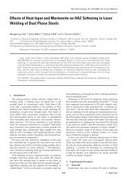
fracture while the DP780 produced a full button. Xia et al. 24)<br />
showed the effects <strong>of</strong> HAZ s<strong>of</strong>tening occurring for various<br />
DP alloys due to post-weld tempering. Higher grades <strong>of</strong> DP<br />
exhibit greater potential for HAZ s<strong>of</strong>tening due to larger<br />
volume fraction <strong>of</strong> martensite which experiences post-weld<br />
tempering. In the current study failure was found to occur<br />
near the HAZ for the higher grade DP780 compared to<br />
interfacial failure occurring for the DP600. BM microstructures<br />
for the dual phase alloys in Fig. 3(a) <strong>and</strong> Fig. 4(a)<br />
showed a higher volume fraction <strong>of</strong> martensite in the DP780<br />
making it more susceptible to HAZ s<strong>of</strong>tening. A detailed<br />
hardness trace from the BM to the FZ for the DP alloys is<br />
shown in Fig. 15. The DP780 exhibited HAZ s<strong>of</strong>tening<br />
compared to the DP600. Tempering <strong>of</strong> martensite within the<br />
DP780 base metal structure therefore evidently promoted<br />
HAZ failure while the lack <strong>of</strong> s<strong>of</strong>tening in DP600 may have<br />
contributed to interfacial failure.<br />
5.2 Fusion zone hardness<br />
The characteristic features <strong>of</strong> columnar grains growing<br />
towards the centerline <strong>and</strong> a largely martensitic microstructure<br />
are common to all the steel types shown in<br />
Figs. 1(d)–5(d). Results have shown the FZ for rich chemistry<br />
steels (DP <strong>and</strong> TRIP) to consist mainly <strong>of</strong> martensite.<br />
Leaner chemistry HSLA showed a mixed FZ microstructure<br />
(martensite <strong>and</strong> bainite), which is likely due to differences<br />
in the HSLA CCT diagram compared to the AHSS. CCT<br />
diagrams for leaner HSLA are usually shifted towards the<br />
left. In these experiments, the early electrode release <strong>and</strong><br />
resulting decrease in cooling rate could bring the bainite<br />
nose within the transformation time to start bainite nucleation<br />
in the FZ during RSW. However, all <strong>of</strong> the AHSS<br />
showed a fully martensitic FZ microstructure <strong>and</strong> so as<br />
expected the FZ hardness is mainly a function <strong>of</strong> alloy levels<br />
within the steel.<br />
Carbon, as an austenite stabilizer, increases the ability to<br />
form martensite (hardenability), <strong>and</strong> is also known to<br />
increase the hardness <strong>of</strong> martensite. Using carbon content<br />
to predict martensite hardness was viable for traditional lean<br />
chemistry steels, which mainly contained only iron <strong>and</strong><br />
carbon <strong>and</strong> low levels <strong>of</strong> other alloying elements. Yurioka<br />
et al. measured martensite hardness <strong>of</strong> various basic oxygen<br />
converter (BOC) steels produced using high cooling rates<br />
achieved from arc welding. 25) Using this experimental data<br />
the following relationship was derived:<br />
H M ¼ 884Cð1 0:03C 2 Þþ294 ð1Þ<br />
Where H M is martensite hardness <strong>and</strong> C is carbon content.<br />
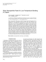
Figure 16 shows the FZ hardness as a function <strong>of</strong> carbon<br />
content for data from this work as well as data from other<br />
researchers. Calculated fusion zone martensite hardness<br />
attained from Equation 1 is also plotted. There were 5 steels<br />
studied in this work with a carbon range from 0.06 to<br />
0.188 mass%. This figure is further populated using experimental<br />
data from several sources including Marya et al., 7)<br />
Gould et al. 26) <strong>and</strong> Uijl et al. 22) who have also done work in<br />
this area.<br />
Examination <strong>of</strong> Fig. 16 shows an over-prediction <strong>of</strong><br />
hardness values for lower carbon steels, which includes an<br />
interstitial free (IF) steel alloy <strong>and</strong> the tested HSLA.<br />
Deviation from predicted values can be attributed to a mixed<br />
martensite-bainite microstructure in the FZ <strong>of</strong> these steels.<br />
Since Equation (1) was developed for martensitic structures,<br />
an over-prediction can occur when applied to lower carbon<br />
steels which do not form a fully martensitic structure.<br />
However the intermediate chemistry steels show a relatively<br />
good agreement to eq. (1).
1636 M. I. Khan, M. L. Kuntz, E. Biro <strong>and</strong> Y. Zhou<br />
Higher carbon steels, including AHSS, show higher FZ<br />
hardness than the predicted values. These steels also contain<br />
higher concentrations <strong>of</strong> alloying elements such as Mn, Mo,<br />
Si <strong>and</strong> Al. The effects <strong>of</strong> these elements on the RSW FZ<br />
hardness are not yet fully understood <strong>and</strong> further research is<br />
required to detail their influence. However, it known that<br />
the addition <strong>of</strong> some alloying elements can enhance the<br />
effectiveness <strong>of</strong> carbon in martensite. 27,28) Also, other studies<br />
have suggested secondary hardening, due to the formation <strong>of</strong><br />
carbides during tempering, resulting in increased material<br />
hardness. 29) Since the early electrode release used here<br />
evidently caused a significant reduction in final cooling rate<br />
for these welds, the martensite formed in the FZ <strong>and</strong> CG<br />
HAZ was likely auto-tempered to some degree, thus<br />
enhancing the influence <strong>of</strong> alloying additions other than<br />
carbon on the final hardness.<br />
The carbon equivalence (CE) value <strong>of</strong> transformable steels<br />
is an index measure which predicts a materials susceptibility<br />
to post-weld cold cracking in the HAZ. The susceptibility to<br />
cold cracking is directly related to the amount <strong>and</strong> hardness<br />
<strong>of</strong> martensite within the HAZ. Alloying elements can aid<br />
in the formation <strong>of</strong> martensite by retarding the kinetics <strong>of</strong><br />
ferrite <strong>and</strong> bainite formation, <strong>and</strong> hence the CE provides an<br />
index measure <strong>of</strong> the effects that alloying elements have on<br />
steel hardenability.<br />
Multiple CE equations are available in literature 30–32)<br />
each taking into account numerous alloying elements, which<br />
include both ferrite <strong>and</strong> austenite stabilizers. Available<br />
30)<br />
equations include the CE IIW <strong>and</strong> P cm developed by Ito<br />
et al. 31) Studies have shown the CE IIW to better suit higher<br />
carbon steels with greater then 0.16% carbon. 33) P cm on the<br />
other h<strong>and</strong> is more appropriate for low-carbon low-alloy<br />
steel. 14) However the wide range <strong>of</strong> carbon contents found in<br />
AHSS can not be accommodated using one simple equation.<br />
Yurioka et al. 34) used various test methods to determine<br />
preheating temperatures required to avoid cold cracking<br />
during welding. In particular, the stout slot weld tests were<br />
carried out on 20 different steels. 35) The steels had various<br />
structural applications with each containing various amount<br />
<strong>of</strong> alloying elements. From this work the following equation<br />
was proposed:<br />
<br />
CE Y ¼ C þ AðCÞ 5B þ Si<br />
24 þ Mn<br />
6<br />
where<br />
þ Cu<br />
15 þ Ni<br />
20<br />
þ<br />
Cr þ Mo þ Nb þ V<br />
5<br />
AðCÞ ¼0:75 0:25 tan hf20ðC 0:12Þg<br />
CE Y is the Yurioka carbon equivalence <strong>and</strong> AðCÞ is an<br />
accommodation factor. Equation (2) contains an accommodation<br />
factor, which approaches 0.5 when carbon is below<br />
0.08% <strong>and</strong> increases to 1.0 with carbon contents above<br />
0.18%. The accommodation factor eliminates the use <strong>of</strong><br />
two CE equations <strong>and</strong> allows for CE Y to be applicable for<br />
steels alloys with carbon contents ranging between 0.02 <strong>and</strong><br />
0.2. Furthermore this single equation can accommodate the<br />
unique chemistries <strong>of</strong> most AHSS.<br />
Alloying elements can aid the formation <strong>of</strong> martensite by<br />
increasing minimum cooling times, hence the CE provides an<br />
<br />
ð2Þ<br />
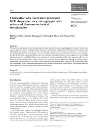
Fig. 17 Fusion zone hardness Vs P cm <strong>and</strong> CE IIW .<br />
Fig. 18<br />
CE Y Vs Fusion Zone Hardness.<br />
effective means <strong>of</strong> measuring the how alloying affects<br />
martensite formation. Figure 17 shows the relationship<br />
between FZ hardness <strong>and</strong> carbon equivalence calculated<br />
using CE IIW <strong>and</strong> P cm for the appropriate carbon range.<br />
Considerable scatter is observed for the CE IIW <strong>and</strong> P cm<br />
equation. Using a linear regression fit, an attempt was made<br />
to find a correlation between carbon equivalence <strong>and</strong> FZ<br />
hardness. However there is minimal agreement <strong>and</strong> the<br />
scatter is reflected in the relatively low linear correlation<br />
coefficient value (r ¼ 59:36%).<br />
CE Y <strong>and</strong> average FZ hardness are plotted in Fig. 18 for<br />
each steel alloy. Trends show FZ hardness increases with<br />
richer chemistries that produce higher CE values. CE Y shows<br />
an improved linear relationship between fusion zone hardness<br />
<strong>and</strong> base material chemistry (r ¼ 96:1%). Extracting<br />
the linear relationship between FZ hardness <strong>and</strong> CE gives<br />
the following equation:<br />
Hv FZ ¼ 630CE Y þ 188<br />
Where Hv FZ is fusion zone hardness <strong>and</strong> CE Y is carbon<br />
equivalence calculated using eq. (2).<br />
Equation (3) provides an improved method for determining<br />
the RSW FZ hardness <strong>of</strong> steels. Compared to eq. (1),<br />
Equation 3 accounts for various alloying elements used in<br />
ð3Þ
<strong>Microstructure</strong> <strong>and</strong> <strong>Mechanical</strong> <strong>Properties</strong> <strong>of</strong> <strong>Resistance</strong> <strong>Spot</strong> <strong>Welded</strong> Advanced High Strength Steels 1637<br />
the production <strong>of</strong> AHSS. By using the Yurioka CE equation,<br />
which includes an accommodation factor for a wide range <strong>of</strong><br />
chemistries, a more reliable relationship between RSW FZ<br />
hardness <strong>and</strong> chemistries can be made, for the particular<br />
resistance welding conditions used here.<br />
6. Conclusions<br />
The current study examined the microstructure <strong>and</strong><br />
mechanical properties <strong>of</strong> RSW AHSS. Using st<strong>and</strong>ard<br />
optimization methods, weldments were made using the<br />
optimal weld conditions <strong>and</strong> compared as to resultant<br />
structure <strong>and</strong> properties. The AHSS consistently achieved<br />
high tensile strength compared to the conventional HSS.<br />
Microstructural observations were presented for the different<br />
weld regions <strong>of</strong> each material. Furthermore, the microstructural<br />
observations <strong>and</strong> hardness testing revealed predominately<br />
harder microstructures within the FZ <strong>of</strong> the<br />
AHSS, which increased with richer chemistry steels. Finally,<br />
an equation to approximate FZ hardness in RSW was<br />
proposed. Some key conclusions include:<br />
(1) The typical IC HAZ microstructure comprised <strong>of</strong><br />
undissolved ferrite <strong>and</strong> dispersed martensite isl<strong>and</strong>s.<br />
The TRIP steel exhibited some retained austenite within<br />
the IC HAZ.<br />
(2) The FZ <strong>and</strong> CG HAZ were mainly comprised <strong>of</strong><br />
martensite for the rich chemistry AHSS alloys. The<br />
leaner chemistry HSLA showed areas <strong>of</strong> ferrite <strong>and</strong><br />
bainite in the CG HAZ, while bainite <strong>and</strong> martensite<br />
was observed in the FZ.<br />
(3) Materials having elevated carbon equivalence experience<br />
increased FZ hardness indicating a strong correlation<br />
between chemistry <strong>and</strong> mechanical properties.<br />
(4) The sole use <strong>of</strong> carbon content was shown to be<br />
insufficient in predicting FZ hardness <strong>of</strong> these resistance<br />
welds. The Yurioka CE equation was found to be<br />
well correlated with FZ hardness values <strong>and</strong> BM<br />
chemistries. FZ hardness can be estimated for a single<br />
pulse weld with a 5 cycle hold time using the following<br />
equation:<br />
Hv FZ ¼ 630 CE Y þ 188<br />
(5) AHSS produced superior tensile failure loads relative to<br />
HSLA. Interfacial fracture was observed during tensile<br />
testing <strong>of</strong> DP600; while button pullout failure modes<br />
occurred for HSLA, 590R, DP780 <strong>and</strong> TRIP780.<br />
REFERENCES<br />
1) K. Banerjee <strong>and</strong> U. K. Chatterjee: Metall. Mater. Trans. A 34A (2003)<br />
1297–309.<br />
2) S. Dinda, C. Belleau <strong>and</strong> D. K. Kelley: International Conference on<br />
Technology <strong>and</strong> Applications <strong>of</strong> HSLA Steels (ASM, 1984)<br />
pp. 475–483.<br />
3) J. Dufourny <strong>and</strong> A. Bragard: Welding in the World 23, No. 5–6, (1985)<br />
100–123.<br />
4) Y. Omiya et al.: R & D Kobe Steel Engineering Reports, 52, No. 3<br />
(2002) 10–14.<br />
5) T. B. Hilditch, D. K. Matlock, B. S. Levy <strong>and</strong> J. F. Siekirk: S.A.E.<br />
transactions [0096-736X] 113 (2005) Iss:Section 5.<br />
6) R. G. Davies: Metall. Mater. Trans. A 9A (1978) 671–679.<br />
7) M. Marya <strong>and</strong> X. Q. Gayden: Welding Journal 85, No. 11 (2005)<br />
172s–182s.<br />
8) W. Tong, H. Tao, X. Jiang, N. Zhang, M. P. Marya, L. G. Hector <strong>and</strong><br />
X. Gayden: Metall. Mater. Trans. A 36 (2006) 2651–2669.<br />
9) M. I. Khan, M. L. Kuntz <strong>and</strong> Y. Zhou: Science <strong>and</strong> Technology <strong>of</strong><br />
Welding <strong>and</strong> Joining 13 (2008) 49–59.<br />
10) S. J. Hu, J. Senkara <strong>and</strong> H. Zhang: Proc. <strong>of</strong> International Body<br />
Engineering Conf. IBEC’96, Body <strong>and</strong> Engineering Section, Detroit<br />
(MI), (1996), p. 91.<br />
11) S. Kou: Welding Metallurgy, 2nd Ed., (J. Wiley & Sons, Inc., Hoboken,<br />
NJ, 2003).<br />
12) H. Zhang <strong>and</strong> J. Senkara: <strong>Resistance</strong> Welding: Fundamentals <strong>and</strong><br />
Applications, (CRC Group, Boca Raton, FL, 2006)<br />
13) C. M. Adams: Welding Journal 37, No. 5, (1958) 210s–215s.<br />
14) H. Suzuki: Trans. Japan Welding Society 10 (1979) 82–91.<br />
15) S. A. Gedeon <strong>and</strong> T. W. Eagar: Metall. Mater. Trans. B 17B (1986)<br />
887–901.<br />
16) W. Tan, Y. Zhou <strong>and</strong> H. W. Kerr: Metall. Mater. Trans. A 33A (2002)<br />
2667–2676.<br />
17) ANSI/AWS/SAE/D8.9-97: Recommended Practices for test methods<br />
for evaluating the resistance spot welding behavior <strong>of</strong> automotive<br />
steels, (1997).<br />
18) F. S. Lepera: Journal <strong>of</strong> Metals 32, No. 3, (1980) 38–39.<br />
19) F. G. Caballero, G. Andrea, C. Carlos <strong>and</strong> D. C. Garcia: Mater. Trans.<br />
47 (2006) 2269–2276.<br />
20) A. Pichler, S. Traint, G. Amoldner, P. Stiaszny, M. Blaimschein <strong>and</strong><br />
E. A. Werner: Proc. 44th MWSP Conference Proceedings 35 (2002).<br />
21) W. D. Callister: Fundamentals <strong>of</strong> Materials Science <strong>and</strong> Engineering,<br />
(John Wiley <strong>and</strong> Sons Ltd, 2004).<br />
22) N. Uijl <strong>and</strong> S. Smith: Advances in <strong>Resistance</strong> Welding, Austria (2006)<br />
30–62.<br />
23) M. I. Khan, M. L. Kuntz, P. Su, A. Gerlich, T. North <strong>and</strong> Y. Zhou:<br />
Science <strong>and</strong> Technology <strong>of</strong> Welding <strong>and</strong> Joining 12 (2007) 175–182.<br />
24) M. Xia, N. Sreenivasan, S. Lawson, Y. Zhou <strong>and</strong> Z. Tian: Journal <strong>of</strong><br />
Engineering Materials <strong>and</strong> Technology 129 (2007) 446–452.<br />
25) N. Yurioka, M. Okumura, T. Kasuya <strong>and</strong> Cotton: Met. Constr. 19<br />
(1987) 217R–223R.<br />
26) J. E. Gould, S. P. Khurana <strong>and</strong> T. Li: Welding Journal 85, No. 5 (2006)<br />
111–116.<br />
27) M. D. Perkas: Met. Sci. Heat Treat. 6 (1968) 415–425.<br />
28) H. Cerjak: Mathematical modelling <strong>of</strong> weld phenomena 3, (Maney<br />
Publishing, 1997).<br />
29) H. Kwon, C. M. Kim, K. B. Lee, H. R. Yang <strong>and</strong> J. H. Lee: Metall.<br />
Mater. Trans. A 28 (1997) 621–627.<br />
30) British St<strong>and</strong>ard Institute. Dec. 1974 Specification for metal-arc<br />
welding <strong>of</strong> carbon <strong>and</strong> carbon manganese steels. BS5135.<br />
31) Y. Ito <strong>and</strong> K. Bessyo: J. <strong>of</strong> Japan Welding Society 37 (1968)<br />
683–991.<br />
32) J. Dearden <strong>and</strong> H. O’Niel: Trans. Int. Weld. 3 (1940) 203–214.<br />
33) T. Yatake, N. Yurioka, R. Kataoka <strong>and</strong> E. Tsunetomi: J. Japan Welding<br />
Society 49 (1980) 484–489.<br />
34) N. Yurioka, H. Suzuki, S. Ohshita <strong>and</strong> S. Saito: Welding Journal 62,<br />
No. 6 (1983) 147–153.<br />
35) R. D. Stout <strong>and</strong> R. Vasudevan: J. Japan Welding Society 37 (1968)<br />
683–991.