
You also want an ePaper? Increase the reach of your titles
YUMPU automatically turns print PDFs into web optimized ePapers that Google loves.
<strong>SCHMIDT</strong> ® Flow S<strong>en</strong>sor<br />
<strong>SS</strong> <strong>20.60</strong><br />
<strong>SS</strong> <strong>20.60</strong> FB<br />
Product description<br />
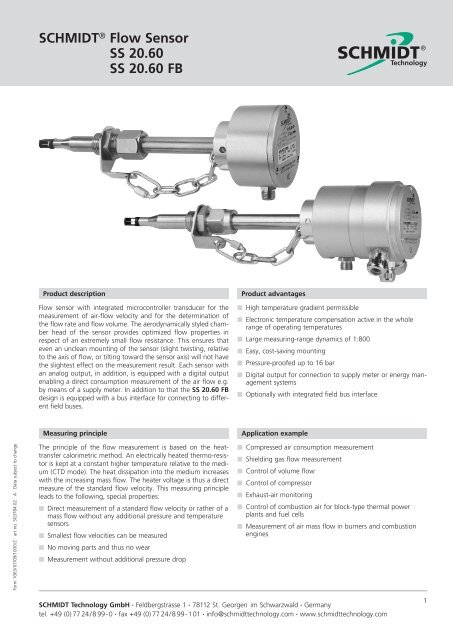
Flow s<strong>en</strong>sor with integrated microcontroller transducer for the<br />
measurem<strong>en</strong>t of air-flow velocity and for the determination of<br />
the flow rate and flow volume. The aerodynamically styled chamber<br />
head of the s<strong>en</strong>sor provides optimized flow properties in<br />
respect of an extremely small flow resistance. This <strong>en</strong>sures that<br />
ev<strong>en</strong> an unclean mounting of the s<strong>en</strong>sor (slight twisting, relative<br />
to the axis of flow, or tilting toward the s<strong>en</strong>sor axis) will not have<br />
the slightest effect on the measurem<strong>en</strong>t result. Each s<strong>en</strong>sor with<br />
an analog output, in addition, is equipped with a digital output<br />
<strong>en</strong>abling a direct consumption measurem<strong>en</strong>t of the air flow e.g.<br />
by means of a supply meter. In addition to that the <strong>SS</strong> <strong>20.60</strong> FB<br />
design is equipped with a bus interface for connecting to differ<strong>en</strong>t<br />
field buses.<br />
Product advantages<br />
n High temperature gradi<strong>en</strong>t permissible<br />
n Electronic temperature comp<strong>en</strong>sation active in the whole<br />
range of operating temperatures<br />
n Large measuring-range dynamics of 1:800<br />
n Easy, cost-saving mounting<br />
n Pressure-proofed up to 16 bar<br />
n Digital output for connection to supply meter or <strong>en</strong>ergy managem<strong>en</strong>t<br />
systems<br />
n Optionally with integrated field bus interface<br />
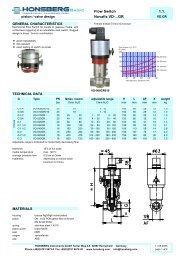
Measuring principle<br />
Application example<br />
Form 1063/07/09/1000/2 · art no. 503784.02 · A · Data subject to change<br />
The principle of the flow measurem<strong>en</strong>t is based on the heattransfer<br />
calorimetric method. An electrically heated thermo-resistor<br />
is kept at a constant higher temperature relative to the medium<br />
(CTD mode). The heat dissipation into the medium increases<br />
with the increasing mass flow. The heater voltage is thus a direct<br />
measure of the standard flow velocity. This measuring principle<br />
leads to the following, special properties:<br />
n Direct measurem<strong>en</strong>t of a standard flow velocity or rather of a<br />
mass flow without any additional pressure and temperature<br />
s<strong>en</strong>sors<br />
n Smallest flow velocities can be measured<br />
n No moving parts and thus no wear<br />
n Measurem<strong>en</strong>t without additional pressure drop<br />
n Compressed air consumption measurem<strong>en</strong>t<br />
n Shielding gas flow measurem<strong>en</strong>t<br />
n Control of volume flow<br />
n Control of compressor<br />
n Exhaust-air monitoring<br />
n Control of combustion air for block-type thermal power<br />
plants and fuel cells<br />
n Measurem<strong>en</strong>t of air mass flow in burners and combustion<br />
<strong>en</strong>gines<br />
<strong>SCHMIDT</strong> <strong>Technology</strong> GmbH · Feldbergstrasse 1 · 78112 St. Georg<strong>en</strong> im Schwarzwald · Germany<br />
tel. +49 (0)7724/899-0 · fax +49 (0)7724/899-101 · info@schmidttechnology.com · www.schmidttechnology.com<br />
1
<strong>SCHMIDT</strong> ® Flow S<strong>en</strong>sor<br />
<strong>SS</strong> <strong>20.60</strong><br />
<strong>SS</strong> <strong>20.60</strong> FB<br />
Product model types<br />
<strong>SS</strong> <strong>20.60</strong><br />
Standard s<strong>en</strong>sor with analog + digital output<br />
• Measuring ranges: up to 200 m/s<br />
• Signal outputs: 1 analog, 1 digital<br />
<strong>SS</strong> <strong>20.60</strong> FB<br />
Design<br />
Remote S<strong>en</strong>sor<br />
Field bus s<strong>en</strong>sor with bus interface integrated in the electronic housing<br />
• Measuring ranges: up to 160 m/s<br />
• Signal outputs: 1 analog, 1 digital<br />
• Field bus:<br />
PROFIBUS DP (V0) or DeviceNet<br />
• Additional functions: calculation of volume flow, monitoring of threshold<br />
value<br />
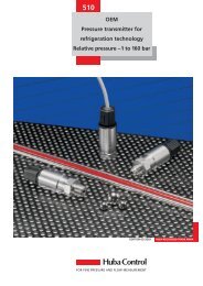
The above m<strong>en</strong>tioned models can be delivered, as shown in the picture, as<br />
so-called compact s<strong>en</strong>sors or as remote s<strong>en</strong>sors.<br />
The remote s<strong>en</strong>sor differs in the following characteristics:<br />
• 3 m cable betwe<strong>en</strong> s<strong>en</strong>sor and electronics, firmly fixed on both sides<br />
• Temperature of the medium up to 120 °C<br />
• Only for operation under atmospheric pressure<br />
Dim<strong>en</strong>sions Compact S<strong>en</strong>sor<br />
Dim<strong>en</strong>sions Remote S<strong>en</strong>sor<br />
7,2<br />
L<br />
17<br />
39,5<br />
190<br />
28<br />
18<br />
29,2<br />
12<br />
48<br />
Ø 9<br />
8<br />
Ø 15<br />
G 1/2<br />
Ø 26<br />
Ø 67,3<br />
36,5 26,5<br />
16<br />
8<br />
tube thread G 1/2<br />
SW 14<br />
10<br />
12,5<br />
15,2<br />
SW 27<br />
SW 24<br />
28<br />
flexible connection<br />
l = 3m<br />
Flow<br />
SW 32<br />
l = 5 m<br />
Ø 5<br />
Dim<strong>en</strong>sions Compact S<strong>en</strong>sor <strong>SS</strong> <strong>20.60</strong> FB<br />
Dim<strong>en</strong>sions Remote S<strong>en</strong>sor <strong>SS</strong> <strong>20.60</strong> FB<br />
190<br />
28<br />
7,2<br />
L<br />
17<br />
82,5<br />
Ø 9<br />
8<br />
18<br />
Ø 15<br />
29,2<br />
G 1/2<br />
12<br />
Ø 26<br />
48<br />
Ø 67,3<br />
Ø 75<br />
79,5 26,5<br />
16<br />
8<br />
SW 14<br />
tube thread G 1/2<br />
10<br />
12,5<br />
15,2<br />
O-Ring<br />
SW 27<br />
SW 24<br />
Flow<br />
screwed cable gland<br />
28<br />
flexible connection<br />
l = 3m<br />
SW 32<br />
All dim<strong>en</strong>sions in mm (if not otherwise noted)<br />
screwed cable gland<br />
2
<strong>SCHMIDT</strong> ® Flow S<strong>en</strong>sor<br />
<strong>SS</strong> <strong>20.60</strong><br />
<strong>SS</strong> <strong>20.60</strong> FB<br />
Technical data<br />
Measuring quantity standard flow velocity w N<br />
normalized to ϑ N = 20 °C and p N = 1013.25 hPa<br />
Measuring fluid<br />
air or nitrog<strong>en</strong><br />
other gases on request<br />
Measuring range (w N) 0 … 200 m/s / 656.2 ft/s<br />
0 … 160 m/s / 524.9 ft/s<br />
0 … 120 m/s / 393.7 ft/s<br />
0 … 60 m/s / 196.9 ft/s<br />
0 … 40 m/s / 131.2 ft/s<br />
0 … 20 m/s / 65.6 ft/s<br />
0 … 10 m/s / 32.8 ft/s<br />
0 … 2.5 m/s / 8.2 ft/s<br />
Lower range limit 0.2 m/s 0.66 ft/s<br />
Lower detection limit 0.1 m/s 0.33 ft/s<br />
Measuring inaccuracy ±(3 % of measurem<strong>en</strong>t value + 0.4 % of measuring<br />
range)<br />
Repeatability<br />
± 0.5 % of measurem<strong>en</strong>t value<br />
Response time (t 90) 3 s (0 to 5 m/s transi<strong>en</strong>t)<br />
Operating temperature<br />
- Compact s<strong>en</strong>sor - 20 ... +85 °C<br />
- Remote s<strong>en</strong>sor - 20 ... + 120 °C<br />
- Electronics 0 ... + 60 °C<br />
Storage temperature -20 ... +85 °C<br />
Humidity range<br />
0 ... 95 % RF<br />
Pressure range<br />
- Atmospheric 700 ... 1300 hPa<br />
- Overpressure 0 ... 16 bar (only compact s<strong>en</strong>sor)<br />
Temperature gradi<strong>en</strong>t 8 K/min @ w N = 5 m/s<br />
Recovery time constant 6 s at temperature jump<br />
∆ϑ air = 40 K, w N = 5 m/s<br />
Temperature dep<strong>en</strong>d<strong>en</strong>ce comp<strong>en</strong>sated within the operating temperature range<br />
Pressure dep<strong>en</strong>d<strong>en</strong>ce indep<strong>en</strong>d<strong>en</strong>t of medium pressure within pressure<br />
range<br />
Zero offset comp<strong>en</strong>sation pressure dep<strong>en</strong>d<strong>en</strong>t adaptation of characteristic<br />
line<br />
Supply voltage U B 24 V DC ± 20 %<br />
Curr<strong>en</strong>t consumption<br />
• Standard<br />
75 mA typ. @ w N = 0 m/s<br />
140 mA typ. @ w N = 200 m/s<br />
• Fieldbus<br />
250 mA typ. @ w N = 160 m/s<br />
Switch-on curr<strong>en</strong>t<br />
• Standard<br />
160 mA for max. 5 s<br />
• Fieldbus<br />
270 mA for max. 5 s<br />
Stabilization time<br />
approx. 10 s after switch-on<br />
1)<br />
Output with error indication according to NAMUR NE43<br />
(error signaling curr<strong>en</strong>t 2 mA)<br />
2)<br />
Tube throughpassage and safety chain are included in delivery of compact s<strong>en</strong>sors.<br />
Remote s<strong>en</strong>sors will solely be delivered with tube throughpassage.<br />
Electrical connection standard s<strong>en</strong>sor<br />
Electrical connection plug-in connector M12, 4-pin<br />
including connection cable with plug,<br />
4 x 0.34 mm², pigtail with wire <strong>en</strong>d sleeve<br />
Cable l<strong>en</strong>gth (standard) 5 m<br />
Cable l<strong>en</strong>gth (adm.)<br />
• Voltage output 15 m<br />
• Curr<strong>en</strong>t output 100 m<br />
• Digital output 100 m<br />
Analog output<br />
selectable wh<strong>en</strong> ordering<br />
• Type voltage<br />
0 ... 10 V<br />
• Type curr<strong>en</strong>t<br />
0 / 4 1) ... 20 mA<br />
Load resistance (adm.)<br />
• Voltage output ≥ 10 kΩ<br />
• Curr<strong>en</strong>t output ≤ 400 Ω<br />
Digital output<br />
pulse output<br />
high level: ≥ U B-3 V<br />
low level: < 0.7 V<br />
load resistance: ≥ 2 kΩ<br />
Digital output frequ<strong>en</strong>cy 0 ... 100 Hz<br />
0 ... 40 Hz<br />
0 ... 20 Hz<br />
0 ... 16 Hz<br />
0 ... 10 Hz (selectable wh<strong>en</strong> ordering)<br />
Digital pulse duration<br />
min. 1 / (2 x f max)<br />
Other features<br />
Housing<br />
aluminium anodised<br />
Probe tube stainless steel X6 CrNiMoTi 1.4571<br />
S<strong>en</strong>sor head<br />
thermoplast PPO/PA<br />
S<strong>en</strong>sor elem<strong>en</strong>t<br />
platinum resistor elem<strong>en</strong>t, glass passivated<br />
Mounting<br />
tube throughpassage, brass,<br />
pressure-proofed, probe tube adjustable,<br />
mounting thread G 1/2 x 12<br />
Mounting tolerance<br />
Installation position<br />
± 5° relative to flow direction<br />
as desired, for vertical downdraft flow lower<br />
range limit approx. 2m/s<br />
Dim<strong>en</strong>sions<br />
• Standard housing 67.3 mm x 56.5 mm (∅ x H)<br />
• Housing field bus 67.3 mm x 103.5 mm (∅ x H)<br />
• S<strong>en</strong>sor head 8 mm x 15.2 mm x 12.5 mm (W x H x D)<br />
• Probe tube<br />
15 mm (∅)<br />
Mounting l<strong>en</strong>gth (L)<br />
• Compact probe 120 / 180 / 250 / 400 mm optionally<br />
• Remote probe 190 mm, remote from housing,<br />
with 3 m connection cable firmly fixed<br />
Weight<br />
450 g max. (without cable)<br />
800 g (<strong>SS</strong> <strong>20.60</strong> FB)<br />
Protection type<br />
IP 65 (housing)<br />
IP 67 (s<strong>en</strong>sor head + tube)<br />
<strong>SCHMIDT</strong> <strong>Technology</strong> GmbH · Feldbergstrasse 1 · 78112 St. Georg<strong>en</strong> im Schwarzwald · Germany<br />
tel. +49 (0)7724/899-0 · fax +49 (0)7724/899-101 · info@schmidttechnology.com · www.schmidttechnology.com<br />
3
<strong>SCHMIDT</strong> ® Flow S<strong>en</strong>sor<br />
<strong>SS</strong> <strong>20.60</strong><br />
<strong>SS</strong> <strong>20.60</strong> FB<br />
Pin assignm<strong>en</strong>t <strong>SS</strong> 25.60 and <strong>SS</strong> 25.60 FB<br />
wh<br />
2<br />
3<br />
1<br />
4<br />
bn<br />
bk<br />
bl<br />
Digital<br />
+ 24 VDC<br />
Analog<br />
GND<br />
Digital output<br />
bk<br />
wh<br />
bn<br />
bl<br />
analog output<br />
U B<br />
View on s<strong>en</strong>sor plug pins.<br />
Color assignm<strong>en</strong>t of connection cable 300 722:<br />
wh = white, bn = brown, bk = black, bl = blue<br />
Minus pole of supply voltage (GND) is also refer<strong>en</strong>ce pot<strong>en</strong>tial for<br />
analog signal.<br />
LED display<br />
The standard version of <strong>SS</strong> <strong>20.60</strong> (not version FB) has a 4-fold double LED status display. The following states are indicated:<br />
No. state LED 1 LED 2 LED 3 LED 4 No. state LED 1 LED 2 LED 3 LED 4<br />
1 operational & flow < 5 %<br />
8 supply voltage too low<br />
2 operational > 5 %<br />
9 supply voltage too high<br />
3 operational > 20 %<br />
10 temperature of electronics too high<br />
4 operational > 50 %<br />
11 temperature of electronics too low<br />
5 operational > 80 %<br />
Leg<strong>en</strong>de<br />
6 operational > 100 % = Overflow<br />
LED off<br />
LED on: orange<br />
7 s<strong>en</strong>sor elem<strong>en</strong>t defective<br />
LED on: gre<strong>en</strong><br />
LED flashes (approx. 2 Hz): red<br />
Field bus interface DeviceNet<br />
Standardization ISO / DIS 11 898<br />
DeviceNet specification volume I + II<br />
release 2.0<br />
Electrical connection 8-pin screw-type terminal inside the housing<br />
cable feed via 3 cable bushings<br />
Terminal resistor The terminal resistor (120 Ohm, 0.25 W) is disabled<br />
on delivery and can be switched in by a<br />
single-pole DIP switch.<br />
Baud rate<br />
125 / 250 / 500 kbit/s, default value 125 kbit/s,<br />
adjustable via DIP switches or by software<br />
Address 0 .. 63, default value of address 63 (MAC ID 63),<br />
can be configured via rotary switch or by software<br />
Operating modes<br />
Process data<br />
Switch thresholds<br />
Warning flag<br />
Alarm flag<br />
Status display<br />
poll mode, Change of State (COS), cyclic<br />
32 bit; volume flow, alternatively flow velocity<br />
selectable<br />
upper and lower switch threshold adjustable for<br />
flow velocity and volume flow<br />
signal wh<strong>en</strong> exceeding measuring range<br />
signal of a defective s<strong>en</strong>sor<br />
two-color LED indicates status of field bus communication<br />
Field bus interface PROFIBUS DP<br />
Standardization<br />
PROFIBUS standard<br />
EN 50 170<br />
Electrical connection 8-pin screw-type terminal inside the housing<br />
cable feed via 3 cable bushings<br />
Terminal resistor The activated network terminal resistor (390-220-<br />
390 Ohm) is disabled on delivery and can be<br />
switched in by a two-pole DIP switch.<br />
Baud rate<br />
9600 Bd – 12 MBd,<br />
automatic adjustm<strong>en</strong>t by PROFIBUS master<br />
Address<br />
00 ... 99, adjustable via BCD rotary switch<br />
Operating modes "Data Exchange" to PROFIBUS DP-V0<br />
Process data<br />
32 bit; volume flow, alternatively flow velocity<br />
selectable<br />
Switch thresholds upper and lower switch threshold adjustable for<br />
flow velocity and volume flow<br />
Warning flag<br />
signal wh<strong>en</strong> exceeding measuring range<br />
Alarm flag<br />
signal of a defective s<strong>en</strong>sor<br />
Status display<br />
two-color LED indicates status of field bus communication<br />
4
<strong>SCHMIDT</strong> ® Flow S<strong>en</strong>sor<br />
<strong>SS</strong> <strong>20.60</strong><br />
<strong>SS</strong> <strong>20.60</strong> FB<br />
Pin assignm<strong>en</strong>t DeviceNet Interface<br />
Electrical connections (screw-type terminals)<br />
1<br />
CAN_L<br />
CAN_H<br />
ON<br />
DRAIN<br />
DRAIN<br />
CAN_L<br />
CAN_H<br />
UB<br />
GND<br />
Pos. Cable color Solder pin/terminal Explanation<br />
1 blue CAN_L CAN negative data line<br />
(dominant low)<br />
2 white CAN_H CAN positive data line<br />
(dominant high)<br />
3 without drain (CAN_SHLD) shield connection<br />
4 without drain (CAN_SHLD) shield connection<br />
5 blue CAN_L CAN negative data line<br />
(dominant low)<br />
6 white CAN_H CAN positive data line<br />
(dominant high)<br />
7 red U B (24 V ±20 %) supply voltage<br />
8 black GND connection to earth<br />
Pin assignm<strong>en</strong>t PROFIBUS Interface<br />
Electrical connections (screw-type terminals)<br />
1 2<br />
ON ON<br />
A<br />
B<br />
UB<br />
GND<br />
A<br />
B<br />
UB<br />
GND<br />
Pos. Solder pin/terminal Explanation<br />
1 A negative serial data line<br />
2 B positive serial data line<br />
3 U B supply voltage (24 V ± 20 %)<br />
4 GND connection to earth<br />
5 A negative serial data line<br />
6 B positive serial data line<br />
7 U B supply voltage (24 V ± 20 %)<br />
8 GND connection to earth<br />
Process data of field bus module<br />
The process data are transmitted<br />
to the bus master via the<br />
the field bus. According to the<br />
adjusted function, you will<br />
obtain the flow velocity or the<br />
volume flow in a 32-bit repres<strong>en</strong>tation<br />
of integers (only positive<br />
values). Optionally, a further<br />
byte can be transmitted<br />
which is transmitting the limit<br />
flag, the alarm flags and the<br />
warning flags.<br />
Parameters Meaning Value range Default value<br />
Flow velocity measured flow velocity w N of 0.00 ... 160.00 0<br />
medium (16 bit) 0<br />
Volume flow volume flow calculated from 0.00 ... 5773265.96 0<br />
flow velocity<br />
(32 bit)<br />
Lower flag lower switch threshold L U 0: w N ≥ L U 0<br />
not reached<br />
1: w N < L U<br />
Upper flag upper switch threshold L O 0: w N ≤ L O 0<br />
exceeded<br />
1: w N > L O<br />
Warning flag measuring range M N exceeded 0: w N ≤ M N 0<br />
1: w N > M N<br />
Alarm flag s<strong>en</strong>sor defective 0: OK 0<br />
1: Error<br />
<strong>SCHMIDT</strong> <strong>Technology</strong> GmbH · Feldbergstrasse 1 · 78112 St. Georg<strong>en</strong> im Schwarzwald · Germany<br />
tel. +49 (0)7724/899-0 · fax +49 (0)7724/899-101 · info@schmidttechnology.com · www.schmidttechnology.com<br />
5
<strong>SCHMIDT</strong> ® Flow S<strong>en</strong>sor<br />
<strong>SS</strong> <strong>20.60</strong><br />
<strong>SS</strong> <strong>20.60</strong> FB<br />
Calculation of volume flow in the field bus module<br />
The s<strong>en</strong>sor with field bus interface can convert the measured flow<br />
velocity w N in a standard volume flow V N if the correct inside<br />
diameter ID has be<strong>en</strong> communicated to the s<strong>en</strong>sor before. The<br />
necessary profile factors PF for the conversion are perman<strong>en</strong>tly<br />
stored in the s<strong>en</strong>sor.<br />
The conversion takes place using the following formula:<br />
UF = Π ⋅ (ID/2) 2 ⋅ PF<br />
V n = w N ⋅ UF ⋅ CF<br />
UF: unit factor<br />
CF: conversion factor<br />
Unit factors (UF):<br />
position unit factor<br />
1 [m 3 /min]<br />
2 [m 3 /h]<br />
3 [l/s]<br />
4 [ft 3 /min]<br />
5 [ft 3 /h]<br />
Mounting instructions<br />
Run-In distance 10 x ID min.<br />
Run-Out distance 5 x ID min.<br />
Ø ID<br />
Mounting parameters<br />
DA<br />
AL<br />
1) SL = welding stud l<strong>en</strong>gth<br />
D A = tube diameter outside<br />
57<br />
E = probe tube setting l<strong>en</strong>gth<br />
AL = compact s<strong>en</strong>sor projecting l<strong>en</strong>gth<br />
R = refer<strong>en</strong>ce l<strong>en</strong>gth<br />
L = probe tube mounting l<strong>en</strong>gth<br />
recomm<strong>en</strong>ded welding stud l<strong>en</strong>gth:<br />
min. 10 mm, max. 30 mm<br />
1)<br />
100 mm for <strong>SS</strong> <strong>20.60</strong> FB<br />
DA /2<br />
SL<br />
L<br />
R<br />
36<br />
E<br />
Formula for calculation:<br />
Which probe l<strong>en</strong>gth is at least necessary?<br />
L > D A /2 + SL + 36 mm<br />
Where must the immersion mark be placed at the probe<br />
tube?<br />
E = L - D A /2 - SL - 36 mm<br />
How much does the s<strong>en</strong>sor projects out of the tube?<br />
AL = L - D A /2 + 57 mm<br />
For <strong>SS</strong> <strong>20.60</strong> FB:<br />
AL = L - D A /2 + 100 mm<br />
6
<strong>SCHMIDT</strong> ® Flow S<strong>en</strong>sor<br />
<strong>SS</strong> <strong>20.60</strong><br />
<strong>SS</strong> <strong>20.60</strong> FB<br />
Selection table probe l<strong>en</strong>gth<br />
Probe l<strong>en</strong>gth Recomm<strong>en</strong>ded for tubes from diameter Suitable for tubes up to Wh<strong>en</strong> installing through ball valve for tubes up to<br />
120 mm DN 25 / 1" DN 65 / 2 1 / 2" –<br />
180 mm DN 50 / 2" DN 150 / 6" DN 25 1) / 1"<br />
250 mm DN 100 / 4" DN 300 / 12" DN 125 / 5"<br />
400 mm DN 250 / 10" DN 800 / 32" DN 450 / 18"<br />
1)<br />
only if welding stud l<strong>en</strong>gth = 10 mm<br />
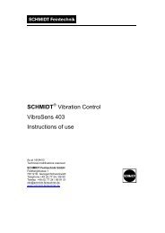
Mounting measurem<strong>en</strong>ts and measuring ranges for measuring tubes<br />
Tube diameters + corresponding PF Mounting measurem<strong>en</strong>ts Measuring range of volume flow in<br />
m 3 /h for s<strong>en</strong>sor measuring range<br />
DN Inside Outside PF L AL E R 60 m/s 120 m/s 160 m/s 200 m/s<br />
25 26.0 31.2 0.796 120.00 160.9 38.4 104.4 91.3 183 243 304<br />
28.5 33.7 0.796 120.00 159.7 37.2 103.2 110 219 292 366<br />
32.8 32.8 0.796 120.00 160.1 37.6 103.6 145 291 387 484<br />
36.3 0.770 120.00 176.5 54.0 120.0 172 344 459 574<br />
40 39.3 44.5 0.748 120.00 154.3 31.8 97.8 196 392 523 653<br />
43.1 48.3 0.757 120.00 152.4 29.9 95.9 239 477 636 795<br />
45.8 51.0 0.763 120.00 151.0 28.5 94.5 272 543 724 905<br />
50 51.2 57.0 0.772 120.00 148.0 25.5 91.5 343 687 916 1.144<br />
54.5 60.3 0.775 120.00 146.4 23.9 89.9 391 781 1041 1.302<br />
57.5 63.5 0.777 120.00 144.8 22.3 88.3 436 872 1162 1.453<br />
64.2 70.0 0.782 120.00 141.5 19.0 85.0 547 1094 1458 1.823<br />
65 70.3 76.1 0.786 120.00 138.5 16.0 82.0 659 1318 1757 2.197<br />
76.1 82.5 0.792 120.00 135.3 12.8 78.8 778 1556 2075 2.594<br />
80 82.5 88.9 0.797 180.00 192.1 69.6 135.6 920 1841 2454 3.068<br />
100 100.8 108.0 0.804 180.00 182.5 60.0 126.0 1386 2772 3696 4.620<br />
107.1 114.3 0.806 180.00 179.4 56.9 122.9 1568 3137 4182 5.228<br />
125 125.0 133.0 0.812 180.00 170.0 47.5 113.5 2152 4305 5740 7.175<br />
131.7 139.7 0.814 180.00 166.7 44.2 110.2 2395 4790 6387 7.984<br />
150 150.0 159.0 0.817 180.00 157.0 34.5 100.5 3119 6237 8316 10.395<br />
159.3 168.3 0.820 180.00 152.4 29.9 95.9 3530 7060 9414 11.767<br />
182.5 193.7 0.825 180.00 139.7 17.2 83.2 4661 9323 12431 15.538<br />
200 206.5 219.1 0.829 250.0 197.0 74.5 140.5 5997 11,994 15,992 19.990<br />
250 260.4 273.0 0.835 250.0 170.0 47.5 113.5 9602 19,205 25,606 32.018<br />
300 309.7 323.9 0.840 250.0 144.6 22.1 88.1 13,668 27,336 36,448 45.560<br />
350 339.6 355.6 0.842 400.0 278.7 156.2 222.2 16,474 32,947 43,930 54.912<br />
400 388.8 406.4 0.845 400.0 253.3 130.8 196.8 21,670 43,339 57,786 72.232<br />
450 437.0 457.0 0.847 400.0 228.0 105.5 171.5 27,440 54,881 73,174 91.468<br />
500 486.0 508.0 0.850 400.0 202.5 80.0 146.0 34,059 68,119 90,825 113.531<br />
550 534.0 559.0 0.852 400.0 177.0 54.5 120.5 41,216 82,432 109,909 137.387<br />
600 585.0 610.0 0.854 400.0 151.5 29.0 95.0 49,581 99,162 132,215 165.269<br />
All dim<strong>en</strong>sions in mm<br />
Calculation volume flow<br />
3<br />
m m ID[<br />
mm]<br />
2<br />
V N<br />
[ ] wN[<br />
] PF <br />
(<br />
) 0,0036<br />
h s<br />
2<br />
V˙ N: standard volume flow<br />
w N: standard flow velocity<br />
PF: profile factor<br />
ID: tube diameter inside<br />
Unit conversion factors<br />
1 m 3 /h 35.315 ft 3 /h<br />
1 mm 0.03937 inch<br />
1000 ft 3 /h 28.317 m 3 /h<br />
1 inch 25.4 mm<br />
<strong>SCHMIDT</strong> <strong>Technology</strong> GmbH · Feldbergstrasse 1 · 78112 St. Georg<strong>en</strong> im Schwarzwald · Germany<br />
tel. +49 (0)7724/899-0 · fax +49 (0)7724/899-101 · info@schmidttechnology.com · www.schmidttechnology.com<br />
7
<strong>SCHMIDT</strong> ® Flow S<strong>en</strong>sor<br />
<strong>SS</strong> <strong>20.60</strong><br />
<strong>SS</strong> <strong>20.60</strong> FB<br />
Accessories<br />
Coupler socket 4-in, with screw-type terminals for cable Ø 4..6 mm (not for <strong>SS</strong> <strong>20.60</strong> FB) 301 008<br />
Connecting cable with coupler socket 4-pin, l<strong>en</strong>gth 10 m, free of halog<strong>en</strong> (not for <strong>SS</strong> <strong>20.60</strong> FB) 300 722-2<br />
Through-bolt joint G½, stainless steel 1.4571, with Viton sealing, multi removable 511 958<br />
Welding sleeve G½, steel, according to EN 10241, 5 pieces 524 916<br />
Welding sleeve G½, stainless steel 1.4571, according to EN 10241, 2 pieces 524 882<br />
Power supply unit 24 V DC output, supply voltage 115/230 V AC 300 640<br />
8 digit display (counter), 72 x 72 x 108 mm, pulse input, 24 V DC 300 838<br />
Spare parts<br />
Connection cable, 4-pin, l<strong>en</strong>gth 5 m 300 722<br />
Tube throughpassage G ½, brass, multi-removable 300 730<br />
Ordering information<br />
Article number:<br />
Description:<br />
506 300 – K- X Y Z S F DD Flow S<strong>en</strong>sor <strong>SS</strong> <strong>20.60</strong><br />
Ordering key:<br />
K- = type<br />
X = probe tube mounting l<strong>en</strong>gth L<br />
Y = measuring range<br />
Z = analog output<br />
S = digital output<br />
F = digital output frequ<strong>en</strong>cy<br />
DD = operating overpressure<br />
Note on scope of delivery:<br />
Type compact s<strong>en</strong>sor:<br />
Type remote s<strong>en</strong>sor:<br />
<strong>SS</strong> <strong>20.60</strong>:<br />
<strong>SS</strong> <strong>20.60</strong> FB:<br />
with tube throughpassage<br />
(300 730) and safety chain<br />
with tube throughpassage<br />
(300 730)<br />
with connection cable,<br />
(300 722) 4-pin, l<strong>en</strong>gth 5 m<br />
with CD Rom with EDS/GSD<br />
file, without connection cable<br />
Type Mounting l<strong>en</strong>gth Measuring Analog<br />
Digital<br />
Digital output Operating<br />
range<br />
output<br />
output<br />
frequ<strong>en</strong>cy<br />
overpressure 1)<br />
K X L Y w N Z S F DD<br />
1 Standard 1 120 mm 1 0 ... 60 m/s 1 0 ... 10 V 1 Pulse output 2 0 ... 100 Hz 00 0 bar 2)<br />
2 DeviceNet with 2 180 mm 2 0 ... 40 m/s 2 0 ... 20 mA 3 0 ... 40 Hz 01 1 bar<br />
cable bushing<br />
4 250 mm 3 0 ... 20 m/s 3 4 ... 20 mA 3) 4 0 ... 20 Hz 02 2 bar<br />
3 PROFIBUS DP with 5 400 mm 4 0 ... 10 m/s 5 0 ... 16 Hz ... ...<br />
cable bushing<br />
3 190 mm / 3 m 4) 5 0 ... 2,5 m/s 6 0 ... 10 Hz ... ...<br />
4 DeviceNet with<br />
6 0 ... 120 m/s 16 16 bar<br />
plug connection<br />
7 0 ... 160 m/s<br />
5 PROFIBUS DP with<br />
plug connection<br />
8 0 ... 200 m/s<br />
1)<br />
Operating overpressure of the medium to be measured at the installation place<br />
2)<br />
Atmospheric air pressure<br />
3)<br />
Option with field bus not possible<br />
4)<br />
Measuring range > 60 m/s not possible, only for operation under atmospheric pressure<br />
Other configuration on request<br />
8