


You also want an ePaper? Increase the reach of your titles
YUMPU automatically turns print PDFs into web optimized ePapers that Google loves.
11<br />
<strong>TPE</strong> E-<strong>circulators</strong><br />
Motors for <strong>TPE</strong> pumps<br />
<strong>Grundfos</strong> variable frequency drive<br />
The variable frequency drive in the MLE motor of the<br />
<strong>TPE</strong>-pump is a highly integrated electronic unit. It is<br />
based on an integrated hybrid module developed by<br />
<strong>Grundfos</strong>.<br />
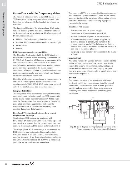
The functional blocks of the single-phase MLE motor<br />
variable frequency drive with PFC-circuit (Power Factor<br />
Correction) are shown in figure 10. Components of<br />
Power electronics are;<br />
• RFI filter (Radio Frequency Interference)<br />
• Rectifier, PFC-circuit and intermediate circuit (1 ph)<br />
• Inrush circuit<br />
• Inverter<br />
EMC (electromagnetic compatibility)<br />
The <strong>Grundfos</strong> MLE motors fulfill the EMC directive<br />
89/336/EEC and are tested according to standard EN<br />
61 800-3. All <strong>Grundfos</strong> MLE motors are equipped with<br />
radio interference filter and varistors in the mains<br />
supply input to protect the electronics against voltage<br />
peaks and noise present in the mains supply<br />
(immunity). All inputs included in the electronic unit are<br />
protected against peaks and noise which can damage<br />
or disturb the function of the unit.<br />
<strong>Grundfos</strong> MLE motors are designed to operate under a<br />
radiated electromagnetic disturbance well above<br />
requirements in EN61 800-3. MLE motors can be used<br />
in both residential areas and industrial areas.<br />
Integrated RFI filter<br />
The integrated radio interference filter (RFI) limits the<br />
amount of electrical noise which the MLE motor emits<br />
to the mains supply network (emission). At the same<br />
time the filter ensures that noise signals in the mains<br />
generated by other equipment do not enter the<br />
electronic devices of the variable frequency drive<br />
causing damage or disturbances.<br />
The purpose of PFC is to ensure that the mains are not<br />
"contaminated" by non-sinusoidal loads which have a<br />
tendency to distort the waveform of the mains voltage<br />
and furthermore cause unnecessarily high peak<br />
currents in the mains.<br />
Benefits of PFC circuit:<br />
• Low reactive load on power supply<br />
• the current will have 40-50% lower RMS<br />
• smaller fuses are required in the installation<br />
• when connecting several pumps supplied by<br />
different phases in parallel, the current in the<br />
common neutral lead will be balanced so that the<br />
neutral lead current will never exceed the current in<br />
any one of the mains phases.<br />
• the pump is less sensitive to variations in the mains<br />
voltage.<br />
Inrush circuit<br />
When the variable frequency drive is connected to the<br />
mains voltage, the intermediate circuit capacitor is<br />
charged to achieve its normal operating voltage. A<br />
series resistor ensures that the charging happens<br />
slowly to avoid large charge spike in supply power and<br />
intermediate capacitors.<br />
Inverter<br />
The inverter consists of six transistors which are<br />
"switched on/off" by control signals from the control<br />
electronics. The transistors have a diode placed in<br />
parallel and are arranged in three branches each<br />
consisting of a series connection comprising two<br />
transistors.<br />
M<br />
3<br />
Rectifier, PFC-circuit and intermediate circuit,<br />
single-phase E-pumps<br />
Single-phase MLE motors are equipped with<br />
PFC-circuit (Power Factor Correction). The purpose of<br />
this circuit is to ensure that the current input from the<br />
mains is sinusoidal and the power factor is close to 1.<br />
The single phase MLE motor range is not covered by<br />
EMC directive and not required to comply with it.<br />
<strong>Grundfos</strong> chose to include the PFC -circuit with the<br />
variable frequency drive design in order to comply with<br />
the EMC directive standard EN 61000-3-2 stipulating<br />
the limits for harmonic current emissions.<br />
Fig. 10 Block diagram showing the functional blocks of the<br />
frequency converter of a single-phase MLE motor<br />
TM02 1203 0601<br />
22


