24VDC Transmitter Manual - Vacuum Research Corp.
24VDC Transmitter Manual - Vacuum Research Corp.
24VDC Transmitter Manual - Vacuum Research Corp.
Create successful ePaper yourself
Turn your PDF publications into a flip-book with our unique Google optimized e-Paper software.
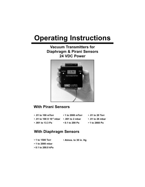
Operating Instructions<br />
<strong>Vacuum</strong> <strong>Transmitter</strong>s for<br />
Diaphragm & Pirani Sensors<br />
24 VDC Power<br />
With Pirani Sensors<br />
• .01 to 100 mTorr<br />
• .01 to 100 X 10 -3 mbar<br />
• .001 to 13.3 Pa<br />
• 1 to 2000 mTorr<br />
• .001 to 2 mbar<br />
• 0.1 to 200 Pa<br />
• .01 to 20 Torr<br />
• .01 to 26 mbar<br />
• 1 to 2660 Pa<br />
With Diaphragm Sensors<br />
• 1 to 1500 Torr<br />
• 1 to 2000 mbar<br />
• 0.1 to 200.0 kPa<br />
• Atmos. to 30 in. Hg
<strong>Vacuum</strong> <strong>Transmitter</strong>s for<br />
Diaphragm & Pirani Sensors<br />
24 VDC Power<br />
• .01 to 100 mTorr • .01 to 100 X 10 -3 mbar • .001 to 13.3 Pa<br />
• 1 to 2000 mTorr • .001 to 2 mbar • 0.1 to 200 Pa<br />
• .01 to 20 Torr • .01 to 26 mbar • 1 to 2660 Pa<br />
• 1 to 1500 Torr • 1 to 2000 mbar • 0.1 to 200.0 kPa<br />
• Atmos. to 30 in. Hg<br />
Contents<br />
Introduction . . . . . . . . . . . . . . . . . . . . . . . . . . . . . . . . . . . . . . . . . . . . . . .1<br />
Specifications . . . . . . . . . . . . . . . . . . . . . . . . . . . . . . . . . . . . . . . . . . . . .1<br />
Pirani Gauges, Analog Output Settings & Circuit Board Maps<br />
.01 to 100 mTorr / .01 to 100 X 10 -3 mbar / .001 to 13.3 Pa . . .2 & 3<br />
1 to 2000 mTorr / .001 to 2 mbar / 0.1 to 200 Pa . . . . . . . . . . . .4 & 5<br />
.01 to 20 Torr / .01 to 26 mbar / 1 to 2660 Pa . . . . . . . . . . . . . . .6 & 7<br />
Diaphragm Gauges, Analog Output Settings & Circuit Board Maps<br />
1 to 1500 Torr / 1 to 2000 mbar / 0.1 to 200.0 kPa . . . . . . . . . . .8 & 9<br />
Atmos. to 30 in. Hg . . . . . . . . . . . . . . . . . . . . . . . . . . . . . . . . .10 & 11<br />
Calibration of <strong>Transmitter</strong> . . . . . . . . . . . . . . . . . . . . . . . . . . . . . . . . . . .12<br />
Gauge Tube Wiring . . . . . . . . . . . . . . . . . . . . . . . . . . . . . . . . . . . . . . .14<br />
i
<strong>Vacuum</strong> <strong>Transmitter</strong>s for<br />
Diaphragm & Pirani Sensors<br />
24 VDC Power<br />
• .01 to 100 mTorr • .01 to 100 X 10 -3 mbar • .001 to 13.3 Pa<br />
• 1 to 2000 mTorr • .001 to 2 mbar • 0.1 to 200 Pa<br />
• .01 to 20 Torr • .01 to 26 mbar • 1 to 2660 Pa<br />
• 1 to 1500 Torr • 1 to 2000 mbar • 0.1 to 200.0 kPa<br />
• Atmos. to 30 in. Hg<br />
These vacuum transmitters are available with Pirani or Diaphragm sensors<br />
in ranges from 10 -5 Torr to 1500 Torr. Instruments are also available<br />
calibrated in microns, in. Hg, PSI, mbar, and Pascal.<br />
The basic transmitter has a non-linear 0 to 5 VDC output and an optional<br />
digital display is available. <strong>Transmitter</strong>s with the digital display have a<br />
linear 0 to 2 VDC output. We recommend that the gauge tube cable with<br />
the connector wired to one end be puchased with the transmitter.<br />
Cables up to 500 feet (150 m) can be used if wire gauge is #22 or larger.<br />
Specifications<br />
Absolute & Differential <strong>Vacuum</strong> Gauges/<strong>Transmitter</strong>s<br />
Power: Gauges operate from 12 to 35 VDC power, 150 mA. for all<br />
ranges except .01 to 20 Torr which requires 300 mA.<br />
Response time: With VRC Pirani; 0.3 sec time constant. With VRC<br />
Diaphragm tubes; less than 400 milliseconds.<br />
Accuracy: Pirani Gauges better than 5% of value or ±3 mT. whichever<br />
is larger. Diaphragm Gauges 1% of reading or ± 2 Torr whichever is<br />
larger.<br />
Relay: SPDT contacts rated for 5A @ 115 VAC, non-inductive.<br />
Remote Sensor Absolute or Differential<br />
1
Pirani Gauges<br />
.01 to 100 mTorr • .01 to 100 X 10 -3 mbar • .001 to 13.3 Pa<br />
Linear analog output for 100 mT transmitters with digital<br />
display 0 to 1 volts, 1 mV = 1 mTorr<br />
Non-linear analog output for 100 mT transmitters without<br />
digital display and linearizer.<br />
OUTPUT<br />
SIGNAL<br />
VOLTS<br />
0.000<br />
0.013<br />
0.026<br />
0.062<br />
0.121<br />
0.180<br />
0.239<br />
0.567<br />
1.065<br />
1.504<br />
1.890<br />
2.225<br />
2.516<br />
2.770<br />
2.992<br />
3.354<br />
3.639<br />
4.054<br />
4.765<br />
5.000<br />
PRESSURE<br />
in mTorr<br />
0.00<br />
0.05<br />
0.10<br />
0.25<br />
0.50<br />
0.75<br />
1.00<br />
2.50<br />
5.00<br />
7.50<br />
10.00<br />
12.50<br />
15.00<br />
17.50<br />
20.00<br />
25.00<br />
30.00<br />
40.00<br />
75.00<br />
100.0<br />
PRESSURE<br />
in mbar<br />
.00000<br />
.00006<br />
.00013<br />
.00033<br />
.00066<br />
.00100<br />
.00133<br />
00333<br />
.00606<br />
.01000<br />
.01333<br />
.01666<br />
.02000<br />
.02332<br />
.02666<br />
.03332<br />
.04000<br />
.05332<br />
0.09997<br />
0.13330<br />
PRESSURE<br />
in Pascal<br />
.000<br />
.006<br />
.013<br />
.033<br />
.066<br />
.100<br />
.133<br />
.333<br />
.666<br />
1.000<br />
1.333<br />
1.666<br />
2.000<br />
2.332<br />
2.666<br />
3.332<br />
4.000<br />
5.332<br />
9.997<br />
13.333<br />
2
Pirani Gauges<br />
• .01 to 100 mTorr • .01 to 100 X 10 -3 mbar • .001 to 13.3 Pa<br />
Gauge with Display<br />
Gauge with No Display<br />
3
Pirani Gauges<br />
• 1 to 2000 mTorr • .001 to 2 mbar • 0.1 to 200 Pa<br />
Linear analog output for 2000 mT transmitters with digital<br />
display 0 to 2 volts, 1 mV =1 mTorr<br />
Non-linear analog output for 2000 mT transmitters without<br />
digital display and linearizer.<br />
OUTPUT<br />
SIGNAL<br />
VOLTS<br />
0.000<br />
0.052<br />
0.105<br />
0.207<br />
0.499<br />
0.726<br />
0.937<br />
1.210<br />
1.319<br />
1.493<br />
1.655<br />
2.450<br />
2.662<br />
3.024<br />
3.686<br />
3.969<br />
4.127<br />
4.402<br />
4.674<br />
4.856<br />
5.000<br />
PRESSURE<br />
in mTorr<br />
0.0<br />
5.0<br />
10.0<br />
20.0<br />
50.0<br />
75.0<br />
100.0<br />
135.0<br />
150.0<br />
175.0<br />
200.0<br />
350.0<br />
400.0<br />
500.0<br />
750.0<br />
900.0<br />
1000.0<br />
1250.0<br />
1500.0<br />
1750.0<br />
2000.0<br />
PRESSURE<br />
in mbar<br />
4<br />
0.0<br />
6<br />
13<br />
27<br />
67<br />
100<br />
133<br />
180<br />
200<br />
233<br />
267<br />
467<br />
533<br />
666<br />
1000<br />
1200<br />
1,333<br />
1,666<br />
2,000<br />
2,333<br />
2,666<br />
PRESSURE<br />
in Pascal<br />
0.0<br />
0.7<br />
1.3<br />
2.7<br />
6.6<br />
10.0<br />
13.3<br />
19.8<br />
20.0<br />
23.3<br />
26.6<br />
46.6<br />
53.2<br />
66.5<br />
99.8<br />
119.7<br />
133.0<br />
166.3<br />
200.0<br />
232.7<br />
266.0
Pirani Gauges<br />
• 1 to 2000 mTorr • .001 to 2 mbar • 0.1 to 200 Pa<br />
Gauge with Display<br />
0 to 5 VDC<br />
Gauge with No Display<br />
5
Pirani Gauges<br />
• .01 to 20 Torr • .01 to 26 mbar • 1 to 2660 Pa<br />
Linear analog output for 20 Torr transmitters with digital<br />
display 0 to 2 volts, 1 mV =10 mTorr<br />
Non-linear analog output for 20 Torr transmitters without<br />
digital display and linearizer.<br />
OUTPUT<br />
SIGNAL<br />
VOLTS<br />
0.000<br />
0.011<br />
0.072<br />
0.149<br />
0.371<br />
0.703<br />
0.989<br />
1.239<br />
1.997<br />
2.530<br />
2.930<br />
3.243<br />
3.800<br />
3.816<br />
3.899<br />
4.057<br />
4.195<br />
4.482<br />
4.695<br />
4.864<br />
5.000<br />
PRESSURE<br />
in Torr<br />
0.000<br />
0.010<br />
0.050<br />
0.100<br />
0.250<br />
0.500<br />
0.750<br />
1.000<br />
2.000<br />
3.000<br />
4.000<br />
5.000<br />
6.000<br />
7.000<br />
8.000<br />
9.000<br />
10.000<br />
12.500<br />
15.000<br />
17.500<br />
20.000<br />
PRESSURE<br />
in mbar<br />
0.000<br />
0.013<br />
0.067<br />
0.133<br />
0.333<br />
0.667<br />
1.000<br />
1.333<br />
2.670<br />
4.000<br />
5.330<br />
6.670<br />
8.000<br />
9.330<br />
10.670<br />
12.000<br />
13.330<br />
16.660<br />
20.000<br />
23.330<br />
26.660<br />
PRESSURE<br />
in Pascal<br />
0<br />
1.33<br />
6.65<br />
13.3<br />
33.25<br />
66.5<br />
99.75<br />
133<br />
266<br />
399<br />
532<br />
665<br />
798<br />
931<br />
1064<br />
1197<br />
1333<br />
1663<br />
1995<br />
2328<br />
2660<br />
6
Pirani Gauges<br />
• .01 to 20 Torr • .01 to 26 mbar • 1 to 2660 Pa<br />
Gauge with Display<br />
Gauge with No Display<br />
7
Diaphragm Gauges<br />
• 1 to 1500 Torr • 1 to 2000 mbar • 0.1 to 200.0 kPa<br />
1 to 1500 Torr<br />
Linear analog output for 1500 Torr transmitters with or without<br />
digital display is 0 to 1.500 VDC, 1 mV =1 Torr<br />
1 to 2000 mbar<br />
Linear analog output for 2000 mbar transmitters with or without<br />
digital display is 0 to 2.000 VDC, 1 mV =1 mbar<br />
0.1 to 200.0 kPa<br />
Linear analog output for 200.0 kPa transmitters with or without<br />
digital display is 0 to 2.000 VDC, 1 mV = 0.1 kPa<br />
8
Diaphragm Gauges<br />
• 1 to 1500 Torr • 1 to 2000 mbar • 0.1 to 200.0 kPa<br />
Gauge with Display<br />
Gauge with No Display<br />
9
Diaphragm Gauges<br />
• Atmos. to 30 in. Hg<br />
Linear analog output for 30 in. Hg transmitters with digital<br />
display is 0 to +300 mV, 1 mV = 0.1 in. Hg<br />
Linear analog output for 30 in. Hg transmitters without digital<br />
display and linearizer.<br />
OUTPUT<br />
SIGNAL<br />
VOLTS<br />
0.000<br />
0.050<br />
0.100<br />
0.200<br />
0.210<br />
0.220<br />
0.230<br />
PRESSURE<br />
in inches Hg<br />
Atmosphere<br />
5.0<br />
10.0<br />
20.0<br />
21.0<br />
22.0<br />
23.0<br />
OUTPUT<br />
SIGNAL<br />
VOLTS<br />
0.240<br />
0.250<br />
0.260<br />
0.270<br />
0.280<br />
0.290<br />
0.300<br />
PRESSURE<br />
in inches Hg<br />
24.0<br />
25.0<br />
26.0<br />
27.0<br />
28.0<br />
29.0<br />
30.0<br />
Gauge Pressure vs. Absolute Pressure<br />
Please note that this is a “Gauge” pressure instrument. The<br />
other instruments in this manual are built to measure pressure<br />
in “Absolute” units such as Torr, Microns, and mbar. “Gauge”<br />
pressure means that atmospheric pressure is used as the reference<br />
for zero and 29.92 in. Hg designates high vacuum.<br />
“Gauge” pressure measurement can be useful in certain applications<br />
such as determining if a vacuum chamber is actually<br />
at atmospheric pressure so that the door can be opened safely.<br />
But, because the zero of “Gauge” measurements changes<br />
with atmospheric pressure the entire scale also changes. For<br />
example, if you are reading 28.00 inches Hg and the next day<br />
your instrument reads 28.39 inches Hg it may be that your<br />
pump is working better or it may be that a storm moved into<br />
your area and atmospheric pressure dropped. Changes in<br />
altitude also affect the readings of “Gauge” pressure instruments.<br />
For example, there is a difference of 5 inches Hg (127<br />
Torr) between sea level and Denver, Colorado.<br />
10
Diaphragm Gauge<br />
• Atmos. to 30 in. Hg<br />
0 to + 300 mV<br />
Gauge with Display<br />
0 to + 300 mV<br />
Gauge with No Display<br />
11
Calibration of <strong>Transmitter</strong><br />
Two methods for calibrating these transmitters are described below.<br />
Calibration using the Reference Gauge Calibrator<br />
This method requires a reference gauge calibrator, and for transmitters<br />
without the optional digital display, you will also need a digital voltmenter<br />
with an accuracy of + 0.1 mV or better and a current calibration<br />
certificate.<br />
Purchase the calibrator from the vacuum gauge manufacturer or your<br />
supplier. And be sure that the calibrator matches the range of your<br />
instrument.<br />
Connect the calibrator in place of the gauge tube and follow the<br />
instructions on the front panel of the calibrator.<br />
Calibration using a Manometer and <strong>Vacuum</strong> System<br />
This method requires a high vacuum system and a certified precision<br />
calibration "standard" such as a capacitance manometer. If your transmitter<br />
does not have a digital display a high quality digital voltmeter will<br />
be required. Be sure the instrument has been turned on with a gauge<br />
tube installed for at least one hour before calibrating.<br />
12
100 mTorr and 2000 mTorr Pirani (See pg. 3 for 100 mT<br />
circuit board map & pg. 5 for 2000 mT circuit board map)<br />
1. Short pins (#5 green wire and #8 white wire) on the terminal strip together.<br />
The tube does not have to be disconnected. Locate the “Offset” pot and<br />
adjust so the digital display reads “000”. Remove the wire short from<br />
between pins 5 and 8.<br />
2. Pump the tube to hard vacuum (1 hour for 100 mT and 30 minutes for<br />
2000 mTorr. Locate the “Zero” pot and adjust so the digital display reads<br />
“000”. Note: Hard vacuum means 10 -6 Torr or lower for 100 mT; 10 -5 Torr or<br />
lower for 2000 mT instruments.<br />
3. Raise the pressure in the system to a known upscale point.<br />
100 mT = 40.00 mT upscale point; 2000 mT = 900 mT upscale point.<br />
Locate the “Span” pot and adjust so the digital display reads the proper<br />
upscale number.<br />
4. Repeat steps 1, 2, and 3 until no further adjustments are necessary.<br />
20 Torr Pirani <strong>Transmitter</strong> (See pg. 7 for circuit board map)<br />
1. Short pins (#6 blue wire and #7 brown wire) on the terminal strip together.<br />
The tube does not have to be disconnected. Locate the “Offset” pot and<br />
adjust so the digital display reads “000”. Remove the wire short from<br />
between pins 6 and 7.<br />
2. Pump the tube to hard vacuum for 30 minutes. Locate the “Zero” pot and<br />
adjust so the digital display reads “0.00”. Note: Hard vacuum means 10 -4<br />
Torr or lower for 20 Torr instruments.<br />
3. Raise the pressure in the system to a known upscale point.<br />
20 T = 9 Torr upscale point.<br />
Locate the “Span” pot and adjust so the digital display reads “9.10”<br />
4. Repeat steps 1, 2, and 3 until no further adjustments are necessary.<br />
1500 Torr Diaphragm <strong>Transmitter</strong> (See pg. 9 for circuit board map)<br />
There are only 2 calibration adjustments that are normally necessary to restandardize<br />
the instrument. One is an offset adjustment. The second is a<br />
span adjustment to set up scale tracking at some known pressure.<br />
Plug in the power cord of the instrument for at least 30 minutes before calibrating.<br />
1. Pump the transducer to “hard vacuum” ( The term “hard vacuum” refers to<br />
any pressure lower than .1 Torr (100 mT). This is a “relative zero” below<br />
which the transducer no longer changes output. It need not be known as<br />
long as you are sure it is this low.) Adjust the OFFSET pot until the meter<br />
reads 0.<br />
2. Vent the transducer to atmosphere. Call the nearest airport weather station<br />
and obtain the immediate barometric pressure. Ask for “station pressure”<br />
not altimeter setting. Multiply the figure you are given for barometric<br />
pressure by 25.4 to convert to mmHg (Torr) from inches Hg. Then,<br />
13
adjust the “Span” pot until the display reads that pressure.<br />
For example, if you are in Pittsburgh and you are at 636 ft. altitude on a<br />
standard day the following is true: at sea level the Std. Barometer is 29.92<br />
in Hg = 760 Torr (29.92 X 25.4 = 759.968 Torr).<br />
This is the altimeter setting for an aircraft, so that at landing the plane’s<br />
altimeter reads 636 ft. (At sea level the altimeter reads 000.)<br />
Multiply the station pressure by 25.4 to convert inches Hg. to Torr and<br />
adjust the span to read the calculated number which in the above example<br />
is 743 Torr.<br />
To obtain this information, look in the phone book under US Government,<br />
Transportation Dept., and call the number for “Pilot One Call Briefing.”<br />
Ask for the “Station Pressure”. Tell them your application is for industrial<br />
calibration purposes.<br />
Atmosphere to 30 in. Hg Diaphragm <strong>Transmitter</strong> (See pg.<br />
11 for circuit board map)<br />
Zero adjustment is made by exposing the transducer to atmospheric pressure<br />
and setting the “Offset” pot to read 000 on the meter.<br />
Pump the transducer to a vacuum that is at least 2 mmHg (Torr) absolute<br />
or lower. It need not be known as long as it is less than the 2 mm Hg.<br />
Obtain the correct barometric pressure and adjust the pot marked “Span”<br />
to read the barometric pressure.<br />
To obtain the correct barometric pressure call the “FAA Pilot one call briefing”<br />
line at your local airport. Ask for the Station Pressure, not the<br />
Altimeter setting.<br />
Gauge Tube Wiring<br />
The gauge tube can be checked with an ohmmeter between pins 1 and 5<br />
to verify that the sensor is good. Generally, the reading is less than 2.5<br />
ohms if good; 900 ohms if the sensor is broken.<br />
The actual readings for each type of tube should be as follows:<br />
SENSOR PINS 1 TO 5<br />
BLACK AND GREEN WIRE<br />
APPROXIMATE RESISTANCE<br />
100 mT 2.4 Ohms<br />
2000 mT 2.1 Ohms<br />
20 Torr 1.3 Ohms<br />
14
Printed 7/26/03<br />
<strong>Vacuum</strong> <strong>Research</strong> <strong>Corp</strong>oration<br />
2419 Smallman Street • Pittsburgh, PA 15222 USA<br />
(800) 426-9340 • (412) 261-7630 • FAX: (412) 261-7220<br />
e-mail: vrc@vacuumresearchcorp.com


