ptac wire harness kit (pwhk01c) installation instructions - Amana PTAC
ptac wire harness kit (pwhk01c) installation instructions - Amana PTAC
ptac wire harness kit (pwhk01c) installation instructions - Amana PTAC

You also want an ePaper? Increase the reach of your titles
YUMPU automatically turns print PDFs into web optimized ePapers that Google loves.
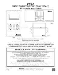
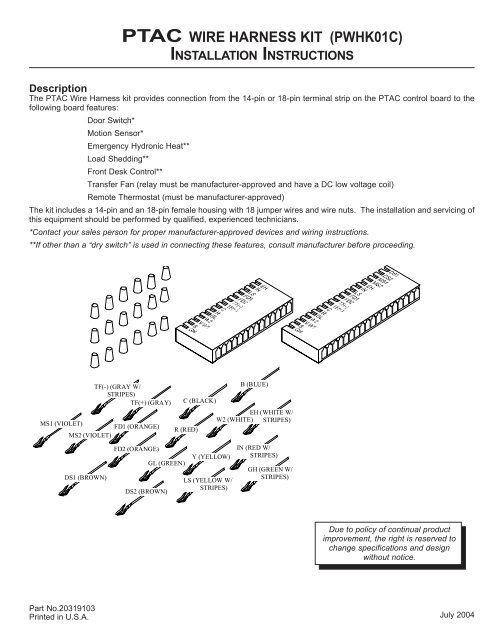
<strong>PTAC</strong> WIRE HARNESS KIT (PWHK01C)<br />
INSTALLATION INSTRUCTIONS<br />
Description<br />
The <strong>PTAC</strong> Wire Harness <strong>kit</strong> provides connection from the 14-pin or 18-pin terminal strip on the <strong>PTAC</strong> control board to the<br />
following board features:<br />
Door Switch*<br />
Motion Sensor*<br />
Emergency Hydronic Heat**<br />
Load Shedding**<br />
Front Desk Control**<br />
Transfer Fan (relay must be manufacturer-approved and have a DC low voltage coil)<br />
Remote Thermostat (must be manufacturer-approved)<br />
The <strong>kit</strong> includes a 14-pin and an 18-pin female housing with 18 jumper <strong>wire</strong>s and <strong>wire</strong> nuts. The <strong>installation</strong> and servicing of<br />
this equipment should be performed by qualified, experienced technicians.<br />
*Contact your sales person for proper manufacturer-approved devices and wiring <strong>instructions</strong>.<br />
**If other than a “dry switch” is used in connecting these features, consult manufacturer before proceeding.<br />
MS1 (VIOLET)<br />
FD1 (ORANGE)<br />
MS2 (VIOLET)<br />
DS1 (BROWN)<br />
TF(-) (GRAY W/<br />
STRIPES)<br />
TF(+) (GRAY)<br />
FD2 (ORANGE)<br />
GL (GREEN)<br />
DS2 (BROWN)<br />
Y (YELLOW)<br />
B (BLUE)<br />
C (BLACK)<br />
EH (WHITE W/<br />
W2 (WHITE) STRIPES)<br />
R (RED)<br />
LS (YELLOW W/<br />
STRIPES)<br />
IN (RED W/<br />
STRIPES)<br />
GH (GREEN W/<br />
STRIPES)<br />
Due to policy of continual product<br />
improvement, the right is reserved to<br />
change specifications and design<br />
without notice.<br />
Part No.20319103<br />
Printed in U.S.A.<br />
July 2004
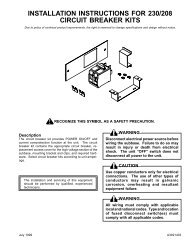
INSTALLATION<br />
WARNING<br />
DISCONNECT ELECTRICAL POWER SOURCE BEFORE WIRING THE UNIT.<br />
FAILURE TO DO SO MAY RESULT IN INJURY OR DEATH FROM ELECTRICAL<br />
SHOCK. THE UNIT "OFF" SWITCH DOES NOT DISCONNECT ALL POWER TO<br />
THE UNIT.<br />
1. Disconnect power and remove the front panel per unit<br />
<strong>installation</strong> <strong>instructions</strong>.<br />
2. Remove 14-pin (or 18-pin, if applicable) female housing<br />
from control board.**<br />
Using the following table and either Figure 1 or 2 as<br />
guides, (Figure 1 for boards with knobs; Figure 2 for<br />
boards with touchpads) choose the feature desired and<br />
insert the proper jumper <strong>wire</strong> into the appropriate slot on<br />
the housing. Ensure the jumper <strong>wire</strong>s are oriented as<br />
shown in Figure 3.<br />
Re-install the 14-pin or 18-pin housing. Ensure housing<br />
faces the direction shown in either Figure 1 or 2. Take<br />
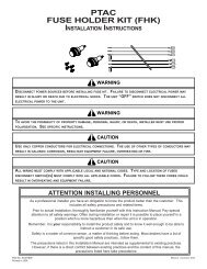
WARNING<br />
ALL WIRING MUST COMPLY WITH APPLICABLE LOCAL AND NATIONAL CODES.<br />
TYPE AND LOCATION OF FUSED DISCONNECT SWITCH(ES) MUST COMPLY<br />
WITH ALL APPLICABLE CODES.<br />
care to ensure the plastic housing and metal pins are<br />
aligned correctly; otherwise, the unit will not funciton<br />
properly.<br />
NOTE: Only load <strong>wire</strong>s intended for <strong>installation</strong>. Extra<br />
<strong>wire</strong>s can be used to connect other <strong>PTAC</strong> boards. One<br />
PWHK01C <strong>kit</strong> can be used for multiple boards.<br />
3. Connect the <strong>kit</strong> wiring to the field wiring using the <strong>wire</strong><br />
nuts provided. Route the <strong>kit</strong> wiring as shown in Figure 4.<br />
Do not run <strong>wire</strong>s through basepan or wall sleeve.<br />
4. With the unit in the OFF position, reconnect the power<br />
and ensure the master switch is in the ON position.<br />
5. Reinstall the front cover per unit <strong>installation</strong> <strong>instructions</strong>.<br />
Check the unit for proper operation.<br />
EH<br />
IN<br />
LS<br />
FD1<br />
FD2<br />
B<br />
TF(-)<br />
TF(+)<br />
C<br />
R<br />
GL<br />
W2<br />
Y/W1<br />
GH<br />
DS1 DS2 MS1 MS2 EH IN LS FD1 FD2 TF- TF+ C R GL W2 Y/W1 B GH<br />
Figure 1: Control Knobs (14-pin Units)<br />
Figure 2: Touchpad (18- Pin Units)<br />
Feature<br />
Pins Used<br />
Emergency Hydronic Heat EH, IN<br />
Load Shedding<br />
LS, IN<br />
Front Desk Control<br />
FD1, FD2<br />
Transfer Fan TF(-), TF (+)<br />
Remote Thermostat<br />
C, R, GL, W2, Y/W1, B, GH<br />
Motion Sensor*<br />
MS1, MS2<br />
Door Switch*<br />
DS1, DS2<br />
Table 1<br />
14-PIN<br />
18-PIN<br />
Figure 3<br />
*These features and connections are only available on touchpad control 18-pin units.<br />
**If a female housing is not present on the control board, use the housing supplied with this <strong>kit</strong>.<br />
2
ON<br />
1 23<br />
Route low voltage <strong>wire</strong> as<br />
shown above. No holes<br />
are permitted in chassis<br />
basepan or wallsleeve<br />
when routing low voltage<br />
<strong>wire</strong>.<br />
Route low voltage <strong>wire</strong> as<br />
shown above. No holes<br />
are permitted in chassis<br />
basepan or wallsleeve<br />
when routing low voltage<br />
<strong>wire</strong>.<br />
Figure 4<br />
3