466600 Oculus Anomaloscope Instructions - PDF - Good-Lite ...
466600 Oculus Anomaloscope Instructions - PDF - Good-Lite ...
466600 Oculus Anomaloscope Instructions - PDF - Good-Lite ...

Create successful ePaper yourself
Turn your PDF publications into a flip-book with our unique Google optimized e-Paper software.
HMC Anomaloskop MR<br />
Moreland and Rayleigh (Typ 47700)<br />
HMC Anomaloskop R<br />
Rayleigh (Typ 47720)<br />
Instruction Manual<br />
Copyright by<br />
G/47700/0403/e
Page 2<br />
Instruction Manual HMC Anomaloskop<br />
__________________________________________________________________________<br />
0. Foreword<br />
Thank you for the confidence which you<br />
have placed in us by purchasing this<br />
OCULUS product. With this unit you have<br />
made your decision for a modern product<br />
which has been manufactured and tested<br />
according to the highest standards of<br />
quality.<br />
Ongoing research and development at<br />
OCULUS, which are certainly in your<br />
interests, may lead to changes in the<br />
design and scope of standard equipment.<br />
The illustrations in this Instruction Manual<br />
may therefore differ in some respects from<br />
the unit as delivered.<br />
Our company can look back on a history<br />
extending more than 100 years into the<br />
past.<br />
OCULUS today is a middle-sized company<br />
whose sole focus is to provide top-quality<br />
products for the support of physicians and<br />
optometrists as they go about their<br />
demanding tasks of ocular examination<br />
and surgery.<br />
Your HMC (Heidelberg-Multi-Color) Anomaloskop<br />
is a microprocessor-controlled<br />
unit with integrated, automatic neutral<br />
adaptation for the precise diagnosis of<br />
color vision in the red-green range<br />
(Rayleigh equation) and the blue-to-bluegreen<br />
range (Moreland equation).<br />
OCULUS incorporated the Rayleigh redgreen<br />
equation several years ago when<br />
developing the Heidelberg Anomaloskop<br />
together with Prof. Krastel of the<br />
University of Heidelberg.<br />
The newest generation, the HMC<br />
Anomaloskop, has now been enhanced<br />
with the Moreland (blue-green) equation.<br />
Here we worked directly with Prof.<br />
Moreland.<br />
Use and control of the unit by the<br />
examinee have been greatly simplified by<br />
an improved ergonomic design, a hinged<br />
tube, and a strategic combination of keys<br />
and control knobs.<br />
The examiner can input information either<br />
via a control unit and an display or with a<br />
PC. When used with a PC, the unit's<br />
program is capable of storing, managing<br />
and comparing patient data and<br />
examination results.<br />
The new FeV (German Driver's License<br />
Ordinance), which went into effect on<br />
January 1, 1999, prescribes that a complete<br />
ophthalmological examination be<br />
carried out for automobile drivers with<br />
special visual requirements.<br />
In the area of color vision, only anomaloscopes<br />
which fulfill the requirements of<br />
DIN-Norm No. 6160 may be used for this<br />
purpose.<br />
The HMC Anomaloskop complies with this<br />
norm.<br />
Proper use is indispensable for safety in<br />
working with the unit. For this reason,<br />
please familiarize yourself thoroughly with<br />
the contents of this Manual before using<br />
the unit for the first time.<br />
Should you have questions or desire<br />
further information about your unit, please<br />
contact us by telephone or send us a<br />
telefax message. Our service team will be<br />
happy to assist you.<br />
OCULUS Optikgeräte GmbH -<br />
The Management and the Staff
Instruction Manual HMC Anomaloskop<br />
Page 3<br />
__________________________________________________________________________<br />
1. Table of Contents<br />
Page<br />
0. Foreword ................................................................<br />
................................................................<br />
......... 2<br />
1. Table of Contents ................................................................<br />
...............................................................<br />
3<br />
2. Standard Equipment List ................................................................<br />
......................................................<br />
4<br />
3. Safety Precautions................................<br />
................................................................<br />
..............................................................<br />
5<br />
4. Description of the Unit and Its Functions ................................................................<br />
6<br />
4.1. Components of the Unit ...................................................................................... 6<br />
4.2. Description of the Unit ........................................................................................ 7<br />
4.3. Description of the Control Unit ............................................................................. 8<br />
4.4. Displays on the Screen of the Control Unit ............................................................. 9<br />
4.5. Warnings and Printed <strong>Instructions</strong> on the Unit......................................................... 9<br />
5. Appropriate Use ................................................................<br />
................................................................<br />
.................................10<br />
6. First Use of the Unit................................<br />
................................................................<br />
............................................................<br />
11<br />
6.1. Before First Use of the Unit ................................................................................. 11<br />
6.2. Setup and Adjustment......................................................................................... 11<br />
6.3. Information about Transport and Storage ............................................................... 11<br />
7. General Remarks on the Color Vision Tests .............................................................<br />
12<br />
7.1. The Anomaly Quotient ........................................................................................ 12<br />
7.2. The Mean Normal Equation .................................................................................. 13<br />
7.3. The Matching Range ........................................................................................... 13<br />
7.4. The Different Examination Programs...................................................................... 13<br />
7.4.1. The Screening Test ...................................................................................... 14<br />
7.4.2. The Manual Test.......................................................................................... 14<br />
7.4.3. Specific Tests ............................................................................................. 14<br />
7.5. Preliminary Test before the Red-Green Test ............................................................ 15<br />
7.6. General Remarks on the Rayleigh Red-Green Test.................................................... 15<br />
7.6.1. Typical Results in Congenital Color Vision Deficiencies ...................................... 16<br />
7.6.2. Typical Results in Acquired Color Vision Deficiencies......................................... 17<br />
7.7. General Remarks on the Moreland Blue-Green Test ................................................. 18<br />
7.8. Overview of Clinical Syndromes: Acquired Color Vision Deficiencies .......................... 19<br />
7.9. Test of Color Vision According to the New FeV (Driver's License Ordinance)............... 20<br />
8. Operation of the Unit ................................................................<br />
..........................................................<br />
21<br />
8.1. Before Every Use................................................................................................ 21<br />
8.2. Preparing the Examinee ....................................................................................... 21<br />
8.3. Examination Procedure With the Control unit .......................................................... 22<br />
8.4. After Every Use ................................................................................................. 23<br />
9. Maintenance ................................................................<br />
................................................................<br />
...... 24<br />
9.1. Care, Cleaning and Disinfection ............................................................................ 24<br />
9.2. Replacing the Fuses............................................................................................ 24<br />
9.3. Troubleshooting ................................................................................................. 25<br />
9.4. Maintenance <strong>Instructions</strong> and Service Intervals ....................................................... 26<br />
10. Terms of Warranty and Service ................................................................<br />
............. 26<br />
10.1. Terms of Warranty ............................................................................................. 26<br />
10.2. Liability for Malfunction or Damage....................................................................... 27<br />
10.3. Manufacturer's and Service Address ..................................................................... 27<br />
11. Appendix................................<br />
................................................................<br />
................................................................<br />
........... 28<br />
11.1. <strong>Lite</strong>rature ......................................................................................................... 28<br />
11.2. Declaration of Compliance ................................................................................... 29<br />
11.3. Order Information, Accessories, Replacement Parts ................................................. 29<br />
11.4. Technical Data................................................................................................... 30<br />
11.5. Test Sheet for the Control Unit............................................................................. 31
Page 4<br />
Instruction Manual HMC Anomaloskop<br />
__________________________________________________________________________<br />
- HMC Anomaloskop MR or<br />
HMC Anomaloskop R<br />
- Control Unit With Display<br />
- Test Notepad (100 pages)<br />
- Mains cable<br />
- This Instruction Manual<br />
- Dust cover<br />
- 2 spare fuses 0.2 A T<br />
(for 230 V-version)<br />
or<br />
- 2 spare fuses 0.4 A T<br />
(for 115 V-version)<br />
2. Standard Equipment List<br />
If you have also selected the software<br />
module for the HMC Anomaloskop (Order-<br />
No. 47703), you will find it included with<br />
the device.<br />
If you have selected only the software<br />
module with or without a PC, the control<br />
unit, the monitor, and the test notepad are<br />
not included in standard delivery.<br />
Please give careful attention to the instruction<br />
manuals which correspond to<br />
each of these products and their accessories,<br />
depending on the technical equipment<br />
which you have received (i.e. control unit<br />
with display or the software module and<br />
PC).<br />
We reserve the right to change the scope<br />
and design of standard equipment during<br />
the course of ongoing technical development<br />
and improvement.
Instruction Manual HMC Anomaloskop<br />
Page 5<br />
__________________________________________________________________________<br />
3. Safety Precautions<br />
The manufacturer is required by law to<br />
provide the user with explicit information<br />
about safety aspects involved in dealing<br />
with this unit. This chapter contains a<br />
summary of the most important<br />
information which should be noted<br />
regarding these points of technical safety.<br />
Further safety instructions are found in the<br />
text of this Instruction Manual and<br />
are designated by the symbol:<br />
Please pay special attention to the<br />
instructions in these passages.<br />
Store this Instruction Manual carefully in a<br />
place where it is accessible for persons<br />
using the unit at all times; also, give due<br />
attention to instruction manuals for the<br />
unit's other accessories as required.<br />
The unit may be used only for its intended<br />
purpose, as described in Chapter 5 of this<br />
Instruction Manual, and by persons whose<br />
proper use of the unit is ensured by their<br />
training and practical experience.<br />
Use the unit only with original parts and<br />
accessories delivered by us and in a<br />
technically flawless condition. Do not<br />
attempt to use the unit should it become<br />
damaged; rather, contact your supplier.<br />
Please abide by accident prevention laws<br />
where applicable, and pay special heed to<br />
the printed instructions and information on<br />
the unit itself.<br />
The unit may be used in medical areas<br />
only if these areas are equipped according<br />
to the VDE 0107 norms of the Association<br />
of German Electrotechnical Engineers or<br />
their equivalent.<br />
Always disconnect all mains plugs from<br />
their power outlets before carrying out<br />
maintenance or cleaning work.<br />
Do not connect any electrical plug and<br />
socket by main force. If it is not possible<br />
to connect them, verify whether the plug<br />
is correct for the socket. If you find<br />
damage in either the plug or the socket,<br />
have them repaired by our service<br />
personnel.<br />
Do not disconnect electric plugs from their<br />
sockets by pulling on the cable, but rather<br />
on the plug in each case.<br />
Auxiliary equipment which is connected to<br />
the analog or digital interfaces of the unit<br />
must meet the respective EN and/or IEC<br />
technical specifications of these interfaces.<br />
Under no circumstances may a coupling of<br />
the HMC Anomaloskop with non-medical<br />
electric devices (e.g. data processing<br />
equipment) for purposes of creating an<br />
integrated electric medical system lead to<br />
a degree of patient safety which is below<br />
that required by IEC Norm 601-1.<br />
Safety equipment in the form of a<br />
disconnecting device must be present if it<br />
is possible that permissible values for<br />
leakage current could be exceeded due to<br />
this coupling.<br />
In addition, all configurations must<br />
conform to IEC Systems Norm 601-1-1.<br />
Do not use the items named in the above<br />
Standard Equipment List in the following<br />
situations:<br />
- Where there is danger of explosion.<br />
- In the presence of flammable anesthetics<br />
or volatile solvents such as alcohol,<br />
benzine or the like.<br />
Do not store or use the unit in damp<br />
rooms. Avoid placing the unit near<br />
dripping, gushing, or splashing water, and<br />
make certain that no fluid can enter the<br />
unit. For this reason, please do not place<br />
any containers full of liquid on or near the<br />
unit. When cleaning the unit with a damp<br />
cloth, take care that no fluid gets into the<br />
unit. Do not cover the air vents.<br />
This unit is a high-quality technical<br />
product. To ensure that it performs<br />
flawlessly and safely, we recommend<br />
having the unit inspected regularly every<br />
two years by our service personnel.<br />
Should any problem arise which you<br />
cannot solve with the enclosed<br />
troubleshooting list, label the unit as "Out<br />
of Order" and contact our service<br />
department.
Page 6<br />
Instruction Manual HMC Anomaloskop<br />
__________________________________________________________________________<br />
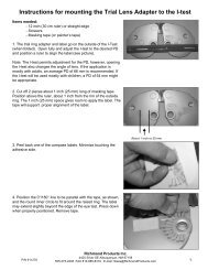
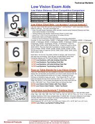
4. Description of the Unit and Its Functions<br />
1<br />
4.1. Components of the Unit<br />
2 5<br />
4<br />
5<br />
3<br />
8<br />
9<br />
7<br />
10<br />
6<br />
No.1 - Eyepiece<br />
No.2 - Housing cover<br />
No.3 - Upper housing, left-hand<br />
No.4 - Upper housing, right-hand<br />
No.5 - Housing caps<br />
No.6 - Lower housing<br />
No.7 - Left key (dissimilar colors)<br />
No.8 - Control knob, Mixed light<br />
No.9 - Control knob, Comparison<br />
light<br />
No.10 - Right key (identical colors)<br />
Figure 1 - HMC Anomaloskop, front view<br />
11<br />
No.11 - Reverse of lower housing<br />
No.12 - Type plate<br />
No.13 - Mains connection<br />
No.14 - Mains switch<br />
No.15 - Fuse drawer<br />
No.16 - Serial interface<br />
12<br />
16<br />
13 14<br />
15<br />
Figure 2 - HMC Anomaloskop, reverse view
Instruction Manual HMC Anomaloskop<br />
Page 7<br />
__________________________________________________________________________<br />
4.2. Description of the Unit<br />
The HMC Anomaloskop does more than<br />
merely allow you to carry out a qualitative<br />
and quantitative diagnostic analysis of<br />
congenital color vision deficiencies. It can<br />
also be of valuable assistance in clarifying<br />
the nature of maculopathy or optic nerve<br />
damage whenever biomicroscopic or<br />
perimetric findings do not lead to a clearcut<br />
diagnosis.<br />
Most anomaloscopes can be used only to<br />
examine red-green vision. This range quite<br />
frequently contains congenital color vision<br />
deficiencies (8% of males, 0.4% of the<br />
female population).<br />
The HMC Anomaloskop MR and R also<br />
meets this standard by using the Rayleigh<br />
equation:<br />
Green (549 nm) + Red (666 nm) =<br />
Yellow (589 nm)<br />
In addition, blue vision can also be<br />
examined with the HMC Anomaloskop<br />
MR. For this the HMC Anomaloskop MR<br />
uses the Moreland equation:<br />
Blue (436 nm) + Green (490 nm) =<br />
Cyan (480 nm) + Yellow (589 nm)<br />
In the case of green, the actual color is<br />
blue-green (turquoise).<br />
The color yellow is used here only for<br />
desaturation of cyan.<br />
We selected the Moreland-type equation<br />
for the HMC Anomaloskop MR because it<br />
has proven itself to be both the most<br />
sensitive and the most specific.<br />
The HMC Anomaloskop utilizes the<br />
principles of additive color mixing and<br />
metamerism.<br />
Two spectral color stimuli are overlapped<br />
in the upper half of the circular viewing<br />
test field, so that the additive color<br />
mixture appears identical with the spectral<br />
color stimulus presented in the lower<br />
hemifield.<br />
The ratio of the light mixture at the top is<br />
variable, and the brightness of the lower<br />
light is varied for comparison until the<br />
viewer subjectively experiences an identity<br />
of the two hemifields in color and<br />
brightness.<br />
In order to achieve reproducible and<br />
comparable results, the following viewing<br />
conditions and modes of presentation<br />
were employed in the HMC Anomaloskop:<br />
- Observation of the viewing test field at<br />
an angle of 2 degrees.<br />
- Sharp focus of the viewing test field by<br />
adjustment of the eyepiece (No. 1,<br />
figure 1)<br />
- Presentation of the viewing test field in<br />
an absolutely dark surrounding.<br />
- Adherence to the wavelength and<br />
bandwidth requirements of the color<br />
stimulus (DIN Norm No. 6160 for the<br />
Rayleigh-type equation).<br />
- Separation of the two halves of the<br />
viewing test field by a thin line; this is<br />
designed to disappear as far as possible<br />
in case of identity.<br />
- Homogeneity of the colored areas was<br />
achieved by mixing the colors in Ulbricht<br />
spheres.<br />
- Neutral adaptation of the eye.<br />
An important prerequisite for carrying out<br />
examinations with the HMC Anomaloskop<br />
is neutral adaptation of the examinee's<br />
eye. Neutral adaptation is achieved in this<br />
unit automatically by fading in white light<br />
from a light source comparable with<br />
standard type C (6770 K) in place of the<br />
viewing test field. Neutral adaptation<br />
occurs at two different intervals,<br />
depending on the selected matching range.<br />
Neutral adaptation is important because<br />
adaptation (accommodation) can occur<br />
when the viewing test field is regarded for<br />
a longer period of time, and this distorts<br />
the examination results.<br />
The upper part of the HMC<br />
Anomaloskop's housing is swivel-mounted<br />
in order to provide the examinee with the<br />
best possible sitting position and thus the<br />
best possible and most non-fatiguing angle<br />
of view.<br />
For downward adjustment, simply press<br />
down on the upper part of the housing to<br />
swivel it downwards. When adjusting it<br />
upwards, hold the bottom part of the<br />
housing lightly at the front in order to<br />
prevent the device from lifting up off the<br />
surface on which it rests.<br />
The HMC Anomaloskop has been provided<br />
with control knobs for improved use of the<br />
unit. These knobs are equipped with a fine<br />
notching mechanism and have no limit<br />
stop. For this reason, an acoustic signal
Page 8<br />
Instruction Manual HMC Anomaloskop<br />
__________________________________________________________________________<br />
signals that the end of the color scale has<br />
been reached.<br />
The control knobs are positioned above<br />
each other, corresponding to the viewing<br />
test fields, to facilitate orientation.<br />
The lower control knob (No. 9 in figure 1<br />
on page 6) is used to adjust the brightness<br />
of the comparison light. The upper knob<br />
(No. 8) is used to adjust the mixed light.<br />
A softer material has been used for the<br />
blue hand rests next to the control knobs<br />
in order to make contact between the<br />
hands and the unit more pleasant.<br />
Note that keys have been integrated into<br />
these hand rests (Nos. 7+10). The right<br />
key is used during the examination to<br />
confirm identity of colors, the left is<br />
pressed in case of dissimilarity.<br />
Here too, an acoustic signal confirms that<br />
a key has been pressed.<br />
At the back of the unit, you will find the<br />
type plate (No. 12, figure 2 in page 6), the<br />
mains connection (No. 13), the mains<br />
switch - illuminated with a green light-<br />
(No. 14), and the fuse drawer at the top<br />
(No. 15).<br />
For best use of the HMC Anomaloskop,<br />
connect our OCULUS PC with its specially<br />
developed Windows TM -compatible software<br />
to the serial interface of the unit (No.<br />
16). You can then electronically store,<br />
manage and compare both, patient data<br />
and examination results.<br />
This software can also be integrated into<br />
most of the widely-used software<br />
modules, which are commonly found in<br />
medical practices.<br />
A less comfortable, but also lower-priced<br />
alternative is offered by the control unit.<br />
The dialogue with the program is then<br />
carried out by means of a 4-line liquid<br />
crystal display with keys, which are<br />
arranged accordingly.<br />
You will find an exact description of the<br />
software modules in the corresponding<br />
instruction manual.<br />
20<br />
18<br />
19<br />
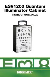
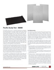
4.3. Description of the Control Unit<br />
17<br />
To lock the plug<br />
in place:<br />
Press the button<br />
when inserting<br />
and/or unlocking!<br />
The basic equipment for operating the<br />
HMC Anomaloskop consists of the control<br />
unit with display.<br />
The program dialogue is carried out via the<br />
keys and the 4-line display (LCD). During<br />
this dialogue, the row of keys below the<br />
display (Figure 3, No. 21) is always<br />
related directly to the text on the screen<br />
(Figure 3, No. 20). These keys change<br />
their allocations/functions during the<br />
examination.<br />
The "Start/Stop" key (Figure 3, No. 22) is<br />
used to start and stop the examination<br />
which is shown in the upper lines of the<br />
display.<br />
The "Next" key (Figure 3, No. 23) is used<br />
to page through the rest of the<br />
examination programs when settings are<br />
being selected.<br />
21<br />
22<br />
Figure 3 - Control unit with display<br />
23<br />
(24)<br />
No. 17 - Locking mechanism<br />
No. 18 - Plug for the serial interface<br />
No. 19 - Housing<br />
No. 20 - Display, 4-line LCD<br />
No. 21 - Row of keys (Allocations change<br />
according to display)<br />
No. 22 - "Start/Stop" key<br />
No. 23 - "Next" key<br />
No. 24 - Type plate (at the back of the<br />
unit)
Instruction Manual HMC Anomaloskop<br />
Page 9<br />
__________________________________________________________________________<br />
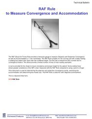
4.4. Displays on the Screen of the Control Unit<br />
A<br />
B<br />
Ray l e i gh absol u te<br />
ma n ua l<br />
s t a n d - b y<br />
Co l o r Examin Ma t chR<br />
Figure 4 - Structure of the display<br />
C<br />
D<br />
E<br />
A) Display of the Selected Color Vision<br />
Test<br />
Options: Rayleigh (Red-Green) or<br />
Moreland (Blue-Green)<br />
(only HMC-MR)<br />
B) Display of Selected Examination<br />
Rayleigh:<br />
Options: Manual,<br />
Screening<br />
or the specific examinations<br />
Normal (person with<br />
normal vision),<br />
Deuteranopia,<br />
Deuteranomaly,<br />
Protanopia or<br />
Protanomaly<br />
Display of Selected Examination<br />
Moreland (only HMC-MR):<br />
Options: Manual,<br />
Screening<br />
or specific examination<br />
Normal (person with<br />
normal vision)<br />
C) Display of Matching Range<br />
Options: Relative (neutral adaptation<br />
after 15 seconds),<br />
Absolute (neutral adaptation<br />
after 5 seconds)<br />
or<br />
NeutOff (without neutral<br />
adaptation)<br />
D) Display of Examination Status<br />
(shows whether an examination<br />
is currently in progress)<br />
Options: Standby or<br />
Aktive<br />
E) Display of Current Keyboard<br />
Allocations<br />
Options: Color,<br />
Examin (Examination),<br />
MatchR (Matching Range),<br />
Menu or<br />
all possibilities under<br />
A) to D)<br />
4.5. Warnings and Printed <strong>Instructions</strong> on the Unit<br />
Caution! / Always disconnect the<br />
mains plug before opening the unit.<br />
Important! / Please read the<br />
accompanying printed material carefully.
Page 10<br />
Instruction Manual HMC Anomaloskop<br />
__________________________________________________________________________<br />
5. Appropriate Use<br />
This unit may be used only for the<br />
purposes described in this Instruction<br />
Manual.<br />
This unit has been designed for precise<br />
qualitative and quantitative diagnosis of<br />
color vision of the human eye in the redgreen<br />
range (HMC Anomaloskop R) and in<br />
the red-green and blue-green ranges (HMC<br />
Anomaloskop MR).<br />
This unit may be used only by persons<br />
whose training and practical experience<br />
ensure that they will work with the unit in<br />
an appropriate manner.<br />
The diagnoses displayed must be individually<br />
verified, since it is quite possible for<br />
false diagnoses to occur due to adjacent<br />
and overlapping defects in color vision or<br />
through input errors on the part of the<br />
patient.<br />
Please use the unit only with original parts<br />
delivered by us and in a technically<br />
flawless condition.<br />
Operate the unit only with an electric<br />
power supply system whose supply<br />
voltage is within the range limits given on<br />
the rating plate.<br />
Please abide by the safety precautions<br />
given above.
Instruction Manual HMC Anomaloskop<br />
Page 11<br />
__________________________________________________________________________<br />
6. First Use of the Unit<br />
6.1. Before First Use of the Unit<br />
Remove the unit and its accessories from<br />
their packing materials and store the<br />
latter. You can then send or transport the<br />
unit correctly should service or repairs<br />
ever be required. In this way you will<br />
avoid unnecessary damage and costs.<br />
Please read this Instruction Manual<br />
carefully.<br />
Before connecting the unit to the electric<br />
power supply system, check whether the<br />
supply voltage of the electric power<br />
supply system is within the range given on<br />
the Type plate (No. 12, figure 2 on page<br />
6).<br />
This optical device should be treated with<br />
care. Do not subject it to vibration,<br />
impacts, soiling or high temperatures.<br />
6.2. Setup and Adjustment<br />
Please set up the HMC Anomaloskop on a<br />
firm, clean and level surface (e.g. a table<br />
surface) in such a way that the air vents<br />
on the bottom of the unit are not covered.<br />
Also avoid setting up the unit near heating<br />
units or moisture which might make its<br />
way into the unit.<br />
In preparation for using the unit for the<br />
first time, connect the control panel (or<br />
the serial cable of the PC) to the jack of<br />
the serial interface (No. 16, Figure 2 on<br />
page 6). Use the mains cable to connect<br />
the mains connection (No. 13) with the<br />
electric power supply. The latter must be<br />
equipped with a protective earth<br />
conductor which is in flawless working<br />
condition.<br />
6.3. Information about Transport and Storage<br />
Please use the original packing material if<br />
you must transport the unit. In this way<br />
you will avoid unnecessary costs and<br />
damage.<br />
Avoid unnecessary impacts when<br />
transporting the unit to another location.<br />
These may have a negative effect on the<br />
optical and electronic components as well<br />
as on the adjustment of the unit.<br />
Inspect the unit for damage whenever it is<br />
relocated. Under no circumstances should<br />
you put the unit into operation if it has<br />
been damaged; instead, please contact our<br />
service representative.<br />
If you keep the unit in a vehicle during the<br />
cold season of the year, its optical parts<br />
may become fogged with condensation<br />
after abrupt changes in temperature from<br />
cold to warm.<br />
Please give the unit time to acclimatize to<br />
its new surroundings before using it for<br />
the first time.<br />
The proper conditions for transporting and<br />
storage according to IEC Norm No. 601-1<br />
are:<br />
- Ambient temperature: -40°C to +70°C<br />
- Relative humidity: 10% to 100%,<br />
including condensation<br />
- Air pressure: 500 hPa to 1060 hPa<br />
These values apply in the unit's original<br />
packaging materials for a period of 15<br />
weeks at most.
Page 12<br />
Instruction Manual HMC Anomaloskop<br />
__________________________________________________________________________<br />
7. General Remarks on the Color Vision Tests<br />
Impairments in color vision are usually<br />
classified as either anomalies or anopia.<br />
"Anomaly" in this case refers to a color<br />
vision deficiency, and "Anopia" refers to<br />
color blindness.<br />
"Protanomaly" and "Protanopia" always<br />
involve the color red, "Deuteranomaly"<br />
and "Deuteranopia" the color green, "Tritanomaly"<br />
and "Trianopia" the color blue.<br />
Both congenital and acquired anomalies of<br />
color vision can be diagnosed qualitatively<br />
and quantitatively with the Red-Green and<br />
Blue-Green color vision tests of the HMC<br />
Anomaloskop.<br />
Examinations of congenital impairments in<br />
color vision, such as protanopia, deuteranopia,<br />
tritanopia, achromatopsia or similar<br />
deficiencies, are usually required for<br />
written evaluative reports and are often a<br />
prerequisite for acquiring licenses (e.g. a<br />
driver's license).<br />
These impairments of color visions may be<br />
evoked by genetic deficiencies or heredity.<br />
However, they always affect both eyes<br />
and remain unchanged during the course<br />
of time.<br />
In patients with congenital color vision<br />
deficiencies, the type of impairment can<br />
be identified immediately inasmuch as the<br />
findings are displayed with absolute<br />
matching range and brightness of the<br />
comparison field.<br />
In the case of congenital protanopia or<br />
deuteranopia, the red-green equation has a<br />
characteristic value which depends on the<br />
respective color vision deficiency. The<br />
blue-green equation, on the other hand, is<br />
usually normal, often somewhat enhanced.<br />
Exactly the opposite is true in congenital<br />
tritanomaly.<br />
Acquired color vision deficiencies have<br />
numerous features in common; these distinguish<br />
them from congenital color vision<br />
deficiencies. The former are usually the<br />
consequence of illness or poisoning, but<br />
may also be related to other visual impairments,<br />
e.g. visual deterioration or visual<br />
field defects. This may make it more<br />
difficult for the examinee to locate the<br />
viewing test field in the anomaloscope.<br />
Impaired adaptation to brightness and<br />
darkness may also make their appearance.<br />
Examination in this case can serve primarily<br />
the purpose of recognizing and monitoring<br />
these disorders.<br />
In contrast to the congenital type, such<br />
color vision deficiencies may affect one<br />
eye alone or both eyes to different degrees<br />
and may also change during the course of<br />
time.<br />
The onset of a deterioration in color vision<br />
manifests itself in the form of a shift or an<br />
increased adjustment of the color equation<br />
in only one of the two color vision tests.<br />
In addition, disorders such as glaucomatous<br />
damage, diabetic retinopathy, retinal<br />
damage in cystoid macular edema, macula<br />
pucker, macular degeneration or central<br />
serous retinopathy as well as drug damage<br />
or toxic retinopathy can be detected and<br />
confirmed.<br />
Both types of color vision deficiencies are<br />
described quantitatively by the Anomaly<br />
Quotient.<br />
7.1. The Anomaly Quotient<br />
The Anomaly Quotient gives the ratio of<br />
the color mixture in the form of a numeric<br />
value and must be determined when the<br />
eye is neutrally adapted, i.e. with relation<br />
to the absolute matching range during the<br />
course of the examination.<br />
The quotient is 1.0 with the mean normal<br />
equation.<br />
The Anomaly Quotient is derived from the<br />
formula:<br />
AQ =<br />
E−<br />
P<br />
P<br />
E−<br />
M<br />
M<br />
The abbreviations here have the following<br />
meanings:<br />
AQ: Anomaly Quotient<br />
E: End value of the light mixture scale.<br />
P: Adjustment value on the light mixture<br />
scale.<br />
M: Color vision adaptation of an observer<br />
with normal color vision.
Instruction Manual HMC Anomaloskop<br />
Page 13<br />
__________________________________________________________________________<br />
The examination results are given in the<br />
form of a pair of numbers, since the<br />
Anomaly Quotient alone provides no information<br />
on the luminance of the comparison<br />
field. In each pair of numbers, the<br />
Anomaly Quotient is given first, followed<br />
by a semicolon and then the respective<br />
value of the comparison field (e.g. 0.9 ;<br />
14).<br />
7.2. The Mean Normal Equation<br />
The color adjustment of the mixed color<br />
field of a colorimetric 2°- normal observer<br />
is designated as the mean normal equation<br />
(cf. also German DIN-Norm No. 5033-2).<br />
In the Red-Green Test, this setting is<br />
about (55±5)% of the upper limit of the<br />
scale, which is 73, i.e. about 40/15.<br />
The ±5% here indicates the permissible<br />
matching range of a normal observer.<br />
The number "15" is related to the value<br />
on the brightness adjustment scale of the<br />
comparison field.<br />
The matching range differs in the two<br />
color vision tests (Red-Green and Blue-<br />
Green), inasmuch as it lies somewhat<br />
higher in the Blue-Green Test.<br />
7.3. The Matching Range<br />
The range of different color mixtures in<br />
the mixed color field, which can be<br />
brought into equilibrium with the comparison<br />
field, is designated as the "matching<br />
range".<br />
The matching range provides an estimate<br />
of the ability to distinguish colors in the<br />
mixed color field. Higher sensitivity in differentiating<br />
between wavelengths is therefore<br />
present whenever the matching range<br />
is low.<br />
The absolute matching range is the basis<br />
for aptitude tests in written evaluations<br />
and certificates. It must be determined<br />
when the eye is neutrally adapted, i.e.<br />
during 5-second cycles of observation of<br />
the colored area. The white fluorescent<br />
surface for neutral adaptation is shown<br />
intermittently.<br />
The relative matching range, on the other<br />
hand, is derived during observation of the<br />
viewing test field for a period of at least<br />
15 seconds. It is usually greater than the<br />
absolute matching range, since adaptation<br />
(or accommodation) takes place when the<br />
viewing test field is regarded for a longer<br />
period of time, and this influences the<br />
examination result.<br />
The relative matching range has special<br />
diagnostic importance in diagnosing acquired<br />
color vision deficiencies. However,<br />
the eyes of some examinees with congenital<br />
color vision deficiencies are also capable<br />
of adaptation.<br />
7.4. The Different Examination Programs<br />
The examination programs which are<br />
available to you are described in the following.<br />
Note: false examination results nearly always<br />
result when the examinee presses<br />
the "Same" key erroneously.<br />
After completion of the different examination<br />
programs, a diagnosis is made for<br />
you. If there is uncertainty about the diagnosis<br />
or no color equation was recognized<br />
as "Same", a message reports to you that<br />
no diagnosis is possible.<br />
The diagnoses which are dis-<br />
played must be individually<br />
verified, since adjacent and<br />
overlapping color vision v<br />
de-d<br />
fects or input errors by the<br />
patient can easily lead to false<br />
diagnoses.
Page 14<br />
Instruction Manual HMC Anomaloskop<br />
__________________________________________________________________________<br />
7.4.1. The Screening Test<br />
This examination program, with its rapid<br />
and uncomplicated procedure, can be used<br />
only as a preliminary test in order to uncover<br />
defects in color vision.<br />
The examinee is shown 6 different color<br />
equations in succession by the program;<br />
he must evaluate them as identical or different.<br />
All known defects in color vision<br />
can be discovered and screened out with<br />
these color equations.<br />
Since it is not desirable here that the examinee<br />
undertake a color adjustment in<br />
the upper mixed color field, only the lower<br />
control knob is put in readiness for him.<br />
He can use this knob, if necessary, to<br />
change the brightness of the lower comparison<br />
field.<br />
If the examinee has evaluated a color<br />
equation as identical or different, a neutral<br />
adaptation is always carried out prior to<br />
the next color equation.<br />
The diagnosis which has been reached is<br />
shown to you at the end of the program.<br />
You must then turn to the manual or specific<br />
tests if more precise information is<br />
required, such as quotients of anomaly<br />
and matching ranges.<br />
7.4.2. The Manual Test<br />
This examination program requires that the<br />
examinee bring the two hemifields into<br />
mutual correspondence by using both control<br />
knobs to adjust them. He uses the<br />
upper control knob to adjust colors in the<br />
mixed field and the lower knob to adjust<br />
the brightness of the comparison light.<br />
We recommend that you first let the examinee<br />
adjust the mixed color field with<br />
the upper control knob, so that he can<br />
acquire a feeling for the adjustment procedure.<br />
After approximate correspondence<br />
has been reached, he must attempt to<br />
arrive at the best possible correspondence<br />
by adjusting the brightness of the comparison<br />
light (lower control knob). It is<br />
quite normal for him to correct the mixed<br />
light adjustment repeatedly during this<br />
time.<br />
The examination starts with the mean<br />
normal equation.<br />
If the examinee confirms a setting as identical<br />
with the right key, the program keeps<br />
this setting. In order to get an indicative<br />
matching range, the value of the color<br />
setting must be changed a little bit before<br />
proceeding with the examination. The<br />
adjustment procedure described above<br />
must then be repeated by the examinee.<br />
You can interrupt the program at any time;<br />
however, please remember that a matching<br />
range can be only determined after at<br />
least two successful settings by the examinee.<br />
The test repeats itself endlessly until you<br />
exit from the examination program.<br />
7.4.3. Specific Tests<br />
Specific tests are recommended whenever<br />
a precise defect in color vision is known or<br />
has been diagnosed by means of the<br />
Screening Test.<br />
The following specific Rayleigh Red/Green<br />
tests can be selected: Normal, Deuteranopia,<br />
Deuteranomaly, Protanopia and Protanomaly.<br />
Only "Normal" can be selected as a specific<br />
Moreland Blue/Green Test (only HMC-<br />
MR) for examinees with normal vision.<br />
These examination programs are even<br />
more precise than the Manual Test, since<br />
they determine each of the two threshold<br />
equations through a process of elimination.<br />
For this purpose, the program selects a<br />
color vision adaptation which lies beyond<br />
the limit of the clinical syndrome in question<br />
(or of the normal range). The examinee<br />
must then evaluate the correspondence<br />
of the colored fields. Since this is<br />
carried out in the same way as with the<br />
Screening Test, he can only influence the<br />
brightness of the comparison field. After<br />
his evaluation (i.e. as identical or different),<br />
the program springs to the opposite<br />
limit of the clinical syndrome (or of the<br />
normal range).
Instruction Manual HMC Anomaloskop<br />
Page 15<br />
__________________________________________________________________________<br />
In this way, the program narrows down<br />
the specific threshold equations precisely,<br />
using large steps at the beginning. These<br />
increments grow steadily smaller during<br />
the course of the examination.<br />
Since the steps at the end are so small<br />
that the color display in the test field<br />
changes only minimally, the examinee<br />
often does not notice this change at all<br />
and reports that the mixture in the color<br />
field remains constant. Even so, he must<br />
carry the examination to its conclusion,<br />
since the sameness of the color display is<br />
illusive, and it is precisely the final options<br />
which deliver the most exact results.<br />
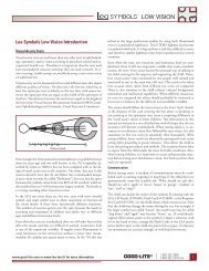
7.5. Preliminary Test before the Red-Green Test<br />
First examine the patient with pseudoisochromatic<br />
charts. In doing so, please<br />
observe the manufacturer's recommendations<br />
regarding proper illumination and<br />
observation distance. We recommend the<br />
use of two chart systems due to differences<br />
in the quality of print.<br />
The sensitivity of these search-and-find<br />
tests is generally above 95% when the<br />
Ishihara plates are used together with a<br />
second series of charts.<br />
Color vision deficiency is very likely the<br />
correct diagnosis if some charts are seen<br />
erroneously or not at all during the test.<br />
It is nearly impossible to differentiate between<br />
protanopia and deuteranopia with<br />
such charts, much less between anomaly<br />
and anopsia. This is possible only with an<br />
anomaloscope.<br />
7.6. General Remarks on the Rayleigh Red-Green Test<br />
The Red-Green Test of the HMC<br />
Anomaloskop uses the Rayleigh equation<br />
for examinations of normal color vision:<br />
Green (549 nm)+ Red (666 nm)=<br />
Yellow (589 nm)<br />
In the horizontally divided viewing test<br />
field, the mixed color field of green and<br />
red is in the upper part and the comparison<br />
field with yellow is below.<br />
The mixed color field can be set from 0 to<br />
73; for example, 73 means a setting of<br />
the mixed color field without the color<br />
green. Persons with normal vision have a<br />
setting of 34 to 46 on the scale here. The<br />
mean value of 40/15 is taken as the mean<br />
normal equation.<br />
The comparison field has a value of 15 on<br />
the scale and can be adjusted from 0 to<br />
45 in brightness.<br />
The Anomaly Quotient with the mean<br />
normal equation is 1.0.<br />
According to the Board of Professional<br />
Norms for Color, examinees with an<br />
Anomaly Quotient of<br />
0 to 1,4 - ∞(infinity) are Deuteranomalous.<br />
Total color blindness (achromatopsia) is<br />
characterized by an extreme loss of<br />
brightness in the direction of red and an<br />
increase of brightness in the direction of<br />
green. Possible adjustment values here<br />
are, for example:<br />
73/1; 60/25; 50/40<br />
The program will show you the results of<br />
evaluation after the examination.<br />
Figure 5 - The Rayleigh Red-Green Color Test
Page 16<br />
Instruction Manual HMC Anomaloskop<br />
__________________________________________________________________________<br />
7.6.1. Typical Results In Congenital Color Vision Deficiencies<br />
A) Anomalies<br />
Anomalies may result from a deficiency in<br />
cone pigment sensitivity to medium or<br />
long wavelengths. The mean normal equation<br />
and the threshold equations are usually<br />
rejected (an exception: extreme<br />
anomalies).<br />
1. Deuteranomaly<br />
"Deuteranomaly" is the most frequent<br />
congenital color vision deficiency. The<br />
green part of the mixture is perceived as<br />
reduced. This is indicated by a designation<br />
of the mean normal equation as "up to<br />
red". Finding an accepted equation by<br />
mixing green into the mixed color field.<br />
Anomaly Quotient: 1.7 to 20.<br />
Extreme deuteranomaly:<br />
Anomaly Quotient: 1.0 to infinity.<br />
2. Protanomaly<br />
Also called "protanomalopia". The red part<br />
of the mixed color field is perceived as<br />
diminished. This is expressed by a designation<br />
of the mean normal equation as "up<br />
to green". Finding an accepted equation<br />
by mixing red into the comparison field<br />
and reducing its brightness. The loss of<br />
brightness is a characteristic feature of<br />
protanomaly.<br />
Anomaly Quotient: 0.6 to 0.11.<br />
Extreme protanomaly:<br />
Anomaly Quotient: 0 to 1.0.<br />
B) Anopia<br />
Anopia is due to the absence of a cone<br />
pigment, so that only a single pigment is<br />
present for the long wavelength half of the<br />
visible spectrum. For this reason there is<br />
no possibility of differentiating between<br />
red and green, and red-green blindness is<br />
the result.<br />
The mean normal equation is accepted.<br />
Both threshold equations are also accepted,<br />
but with different distributions of<br />
light intensity depending on the type of<br />
anopia. Anopia has no Anomaly Quotient.<br />
1. Deuteranopia<br />
Red-green blindness due to an absence of<br />
cones which are sensitive to medium<br />
wavelengths.<br />
The mean normal equation and both<br />
threshold equations are accepted, but both<br />
tend towards yellow light intensities of<br />
about 15. The absence of major differences<br />
in brightness between the threshold<br />
equations is characteristic.<br />
2. Protanopia<br />
Red-green blindness due to the absence of<br />
cones which are sensitive to long wavelengths.<br />
The mean normal equation and both<br />
threshold equations are accepted, but a<br />
very bright yellow (about 30 increments<br />
on the scale) is selected for the green<br />
threshold equation (0 on the scale) and a<br />
very dark yellow (about 5 on the scale) for<br />
the red threshold equation (73 on the<br />
scale). This loss of brightness in the direction<br />
of red is characteristic of protanopia.<br />
Differences in brightness may be designated<br />
by the patient as differences in<br />
color. Brightness adaptation should always<br />
be carried out first for this reason, and the<br />
patient should then be asked about identity<br />
of colors.<br />
C) Achromatopsia<br />
Congenital, total color blindness, absence<br />
of all cone functions: rod monochromatism.<br />
In spite of a poor visual acuity of about<br />
0.1, the viewing test field of the HMC<br />
Anomaloskop is easily found by the examinee.<br />
The red threshold equation (73 on<br />
the scale) is perceived as extremely dark<br />
(darker than in protanopia).<br />
There is an extreme increase of brightness<br />
toward green: A yellow of about 40 on<br />
the scale is selected for a mixed light of<br />
50 on the scale. This corresponds to the<br />
perception of brightness by the rods.
Instruction Manual HMC Anomaloskop<br />
Page 17<br />
__________________________________________________________________________<br />
7.6.2. Typical Results in Acquired Color Vision Deficiencies<br />
A) Widening of the Setting Range<br />
During progressive retinal and optic nerve<br />
diseases which affect either the central<br />
visual field either alone or together with<br />
other areas, the matching range increases<br />
on the HMC Anomaloskop. The relative<br />
matching range (observation of the viewing<br />
test field > 15 s) may be particularly<br />
enhanced in patients with acquired color<br />
vision deficiencies.<br />
A symmetric widening of the matching<br />
range, starting within normal limits, or a<br />
tendency towards an increase toward<br />
green, is frequently found in conductivity<br />
disorders of the optic nerve. This initially<br />
proceeds without loss of brightness,<br />
which then appears in the advanced<br />
stages. Typical examples: retrobulbar optic<br />
neuritis, other optic nerve injuries (e.g.<br />
toxic: ethambutol).<br />
B) Pseudo-Protanomaly<br />
Protanomaly<br />
The equation of the HMC Anomaloskop<br />
typically shifts towards red in the case of<br />
inflammatory, toxic and hereditary macular<br />
diseases. In the process, there is also a<br />
loss of brightness. For this reason the<br />
findings may be identical to those of protanomaly<br />
with regard both to the position<br />
of the equation and the reduced brightness<br />
of the control yellow.<br />
Typical examples: central serous retinopathy,<br />
chloroquine maculopathy, Stargardt's<br />
macular degeneration.<br />
As the disorder progresses, particularly in<br />
the case of degenerative macular processes,<br />
there is an increase in the red shift,<br />
a widening of the setting range, and a loss<br />
of brightness towards red, possibly to the<br />
point of scotopia.<br />
C) Scotopia<br />
A complete loss of cone function may<br />
result if there is pronounced cone damage<br />
in the tested visual field. The examinee<br />
then uses the rods, i.e. his own scotopic<br />
system, for the evaluation of color vision<br />
adaptation. We speak of "scotopia" in this<br />
case. The examination result resembles<br />
that of congenital achromatopsia. The<br />
extremely abrupt increase of brightness<br />
towards green in the accepted equations,<br />
and the extreme loss of brightness towards<br />
red, correspond to the long wavelength<br />
flank of the rhodopsin wavelength,<br />
i.e. rhodopsin, the visual substance of the<br />
rods.
Page 18<br />
Instruction Manual HMC Anomaloskop<br />
__________________________________________________________________________<br />
7.7. General Remarks on the Moreland Blue-Green Test (only HMC-MR)<br />
The Blue-Green Test of the HMC<br />
Anomaloskop uses the Moreland equation<br />
to evaluate normal color vision:<br />
Blue (436 nm) + Green (490 nm)=<br />
Cyan (480 nm) + Yellow (589 nm)<br />
The horizontally divided, two-part viewing<br />
test field consists of an upper, mixed color<br />
field of green and blue and a lower comparison<br />
field with cyan and desaturation<br />
with yellow.<br />
The mixed color field can be adjusted from<br />
0 to 100; 100, for example, results in a<br />
setting of the mixed color field without the<br />
color blue.<br />
The comparison field can be adjusted in<br />
brightness from 0 to 100.<br />
The mean value of 50/50 has been selected<br />
as the mean normal equation.<br />
The Anomaly Quotient is 1.0 with the<br />
mean normal equation as well.<br />
Congenital impairments in the blue area<br />
(tritanomaly) have a frequency of ca.<br />
0.003 % and are therefore much less<br />
common than congenital impairments in<br />
the red-green area. Men and women are<br />
affected equally often by tritanomaly.<br />
Confirmation of these impairments is<br />
much more difficult than that of red-green<br />
impairments due to pronounced individual<br />
differences in macular pigmentation,<br />
which heavily affects the perception of<br />
blue.<br />
In contrast, the Blue-Green Test is very<br />
important for the examination of acquired<br />
color vision deficiencies and for early detection<br />
of progressive diseases and intoxication<br />
of the retina and the optic nerve.<br />
These may be macular diseases, retinitis<br />
pigmentosa, diabetes mellitus, dominant<br />
hereditary optic nerve atrophy, or various<br />
types of optic nerve and retinal damage.<br />
If an acquired color vision deficiency displays<br />
a shift of the blue-green equation<br />
towards blue (0 on the scale), we speak of<br />
pseudo-tritanomaly.<br />
You should suspect glaucoma, diabetes,<br />
achromatopsia, or monochromasy of the<br />
retinal blue photoreceptors if the adjustments<br />
made by the examinee are located<br />
in the areas shown in Figure 6.<br />
100<br />
80<br />
60<br />
40<br />
20<br />
Suspect of<br />
Blue cone<br />
Monochromasy<br />
Suspect of<br />
glaukoma / diabetes<br />
Suspect of<br />
Achromatopsie<br />
0<br />
0 20 40 60 80 100<br />
Figure 6 - The Moreland Blue-Green Color Scale<br />
The clinical importance has become increasingly<br />
clear with the availability of the<br />
Blue-Green Test. All disorders which undermine<br />
spatial organization in the retina<br />
and the optic nerve increase the likelihood<br />
that the Blue-Green Test will reveal early<br />
pathologic changes.<br />
The findings in older persons depend on<br />
the thickness of the lens. In spite of normal<br />
visual acuity levels, a slight shift towards<br />
blue in the blue-green equation appears<br />
here with increasing thickness of the<br />
lens. This must be taken into account<br />
when assessing the results.
Instruction Manual HMC Anomaloskop<br />
Page 19<br />
__________________________________________________________________________<br />
7.8. Overview of Clinical Syndromes: Acquired Color Vision Deficiencies<br />
The following interrelationships between<br />
specific categories of disease and changes<br />
in color vision were determined by Hermès,<br />
Roth and Borot (1989).<br />
Acquired Color Vision Deficiencies<br />
Early Stages<br />
Advanced Stages<br />
Color vision Midpoint of Matching Midpoint of Matching Results<br />
deficiencies Matching Range Range Matching Range Range<br />
Red/Green R Pseudo-<br />
Normal Pseudo-<br />
Wider a)<br />
Protanomaly<br />
Protanomaly<br />
M Normal Normal n. green shift Wider<br />
Red/Green+ R Normal Normal Normal Wider (R
Page 20<br />
Instruction Manual HMC Anomaloskop<br />
__________________________________________________________________________<br />
7.9. Color Vision Testing According to the New FeV<br />
(German Driver's License Ordinance)<br />
Minimum legal visual requirements on the<br />
part of those who apply for a driver's license<br />
are described in § 12 of the FeV<br />
(German Driver's License Ordinance) of<br />
January 1, 1999 and in Appendix 6 of the<br />
same.<br />
Color recognition provides automobile<br />
drivers with valuable and important additional<br />
information in many traffic situations.<br />
A person with impaired color vision<br />
can make only partial use or none at all of<br />
information which the trichromatic person<br />
perceives. Especially important here is a<br />
good recognition of red signal lights, e.g.<br />
the position and brake lights of vehicles<br />
ahead, especially under poor conditions of<br />
visibility.<br />
Poor conditions of visibility can occur during<br />
driving in fog, in heavy rain, during a<br />
snowstorm, against the sun when it is low<br />
on the horizon, or when there is dirt on<br />
the headlights.<br />
Limited perception in the red range (protanopia<br />
and protanomaly) is therefore relevant<br />
for automobile traffic. For this reason,<br />
legal restrictions are required for this<br />
area.<br />
The signal colors of traffic lights, on the<br />
other hand, can usually be correctly recognized<br />
and classified even by persons<br />
with impaired color vision.<br />
The test of color vision must be carried<br />
out with suitable color panel systems or<br />
with color vision test disks. Two different<br />
systems must always be used for the examination,<br />
since slight deviations in color<br />
can result from different qualities of print.<br />
If errors occur during the test, §§ 12 and<br />
48, Paragraphs 4 and 5 of the abovenamed<br />
ordinance prescribe an examination<br />
with the anomaloscope as mandatory for<br />
applicants for driver's licenses in categories<br />
C, C1, CE, C1E, D, D1, DE, D1E and<br />
the Driver's License for Transport of Passengers.<br />
Appendix 6 requires in paragraph<br />
2.2.2 a quotient of anomaly of at least<br />
0.5 with an absolute matching range.<br />
If an anomaly is found, AQ is evaluated as<br />
the value which deviates farthest from the<br />
mean normal equation as a result of examination<br />
with the anomaloscope.<br />
An impairment in color vision does not<br />
constitute a reason for disqualification for<br />
driver's licenses in categories A, A1, B,<br />
BE, M, L and T. The person affected must<br />
merely be made aware of the possible<br />
dangers of this situation in automobile<br />
traffic.<br />
According to the FeV (Driver's License<br />
Ordinance), the quotient of anomaly for<br />
categories C, C1, CE, C1E must be determined<br />
with an anomaloscope. As before,<br />
however, it suffices to inform the affected<br />
person about the possible dangers. The<br />
person must be made aware of the fact<br />
that he must always maintain a greater<br />
safety distance from the vehicle in front of<br />
him in order to compensate for his handicap.<br />
It is to be noted in passing that this<br />
regulation contradicts the recommendations<br />
of the German Ophthalmological<br />
Association in Heidelberg.<br />
Driver's licenses in the categories D, D1,<br />
DE, D1E and the Driver's License for<br />
Transport of Passengers are not permitted<br />
in case of protanopia and protanomaly<br />
with an AQ of less than 0.5.
Instruction Manual HMC Anomaloskop<br />
Page 21<br />
__________________________________________________________________________<br />
8. Operation of the Unit<br />
8.1. Before Every Use<br />
Before each use, please check to make<br />
sure that:<br />
- The unit is in flawless technical<br />
condition.<br />
- All cables and plugs are in flawless<br />
working condition.<br />
- You are using the unit with the mains<br />
cable designed for the unit.<br />
- You have inserted the mains plug into a<br />
power outlet, which is equipped with a<br />
protective earth conductor in flawless<br />
working condition.<br />
When using the unit with a<br />
PC, please turn on the PC first<br />
and then the HMC<br />
Anomaloskop.<br />
Always comply with the ap-<br />
a<br />
propriate instruction i<br />
manuals<br />
which are found included i<br />
with<br />
the software module and the<br />
PC.<br />
Use the green mains switch on the back<br />
side of the unit to turn on the unit before<br />
using it to carry out an examination.<br />
8.2. Preparing the Examinee<br />
Ask the examinee to sit in a relaxed<br />
manner in front of the unit.<br />
The upper part of the HMC<br />
Anomaloskop's housing has been provided<br />
with a swivel-mount to ensure both the<br />
best sitting position, i.e. a non-fatiguing<br />
posture, and the best possible angle of<br />
view for the examinee.<br />
Always make sure that nothing<br />
can interfere with the unit's<br />
rotation and that your own<br />
fingers and those of the ex-<br />
e<br />
aminee are out of the way.<br />
To adjust the unit downwards, simply<br />
press down on the upper part of the housing.<br />
When adjusting the unit upwards, lightly<br />
hold the bottom part of the housing at the<br />
front to keep the unit from lifting up off<br />
the surface on which it stands.<br />
Explain the positions, function and arrangement<br />
of the control knobs and push<br />
buttons to the examinee.<br />
Inform the examinee which eye will be<br />
examined first. The examinee should relax<br />
as much as possible and look into the<br />
middle of the aperture with this eye, so<br />
that the viewing test field is exactly centered<br />
in his gaze. The examinee can keep<br />
the unexamined fellow eye open or closed,<br />
whichever he finds easier.<br />
Alert the examinee to the fact that a<br />
white, luminous field will appear during<br />
the examination and that during this phase<br />
he must continue to gaze into the eyepiece<br />
in order to maintain neutral adaptation<br />
of his eye.<br />
If the examinee reports an absence of<br />
either neutral adaptation or the viewing<br />
test field, please interrupt the examination<br />
and follow the instructions in Chapter 9.3.<br />
(Troubleshooting).<br />
Best results are obtained when the examinee<br />
sees the viewing test field with its<br />
border in sharp focus. To achieve this, he<br />
can correct his own visual acuity at the<br />
eyepiece at the beginning of the examination.<br />
The unit is capable of a correction of<br />
±6 diopters. If this diopter adjustment<br />
range is insufficient, the examinee can use<br />
his own eyeglasses or contact lenses.<br />
Under no circumstances should<br />
the eyeglasses or contact lens<br />
be tinted, since this affects<br />
the results of measurement.
Page 22<br />
Instruction Manual HMC Anomaloskop<br />
__________________________________________________________________________<br />
8.3. Examination Procedure With the Control Unit<br />
The HMC Anomaloskop carries out a selftest<br />
as soon as it is turned on with the<br />
mains switch (Figure 2, No. 14 on page<br />
6). During this period, two black bars can<br />
appear on the screen. The following interim<br />
display appears briefly on the screen<br />
immediately following this self-test (Figure<br />
7).<br />
OCULUS<br />
Op t i k ge r ä t e Gmb H<br />
D -35582 We t z l a r<br />
Ve r s i on 1.00<br />
Figure 7 - Interim display after the unit is turned on<br />
The number of the program version is<br />
found in the last line (here: 1.00). Please<br />
give this number when making inquiries.<br />
Above this interim display, the program<br />
automatically proceeds on to the following<br />
basic settings (Figure 8).<br />
Press the key under "Examin" if you wish<br />
to set the unit for a different examination<br />
program. You will then be shown the following<br />
display (Figure 10) on the screen.<br />
Ray l e i gh<br />
ma n ua l<br />
absol u te<br />
s t a n d - b y<br />
Sc r een i ng<br />
normal<br />
Figure 10 - Selection of examinations<br />
Now you can use the left key to select the<br />
Screening Test or the right key to select a<br />
specific examination for a person with<br />
normal vision.<br />
Please use the "Next" key of the control<br />
unit (Figure 3, No. 23 on page 8) to select<br />
other examinations. The following display<br />
on the screen is intended to serve as an<br />
example for the other specific examination<br />
programs (Figure 11).<br />
Rayl ei gh<br />
ma n ua l<br />
absol ute<br />
s t a n d - b y<br />
Rayl e i gh<br />
ma n ua l<br />
absol ute<br />
s t a n d - b y<br />
Co l o r Examin Ma t chR<br />
Figure 8 - Display of basic settings<br />
This set of basic settings appears each<br />
time the unit is turned on, even if the program<br />
was previously ended with other<br />
settings.<br />
Press the "Start/Stop" key of the control<br />
unit in order to carry out an examination<br />
with these settings, (Figure 3, No. 22 on<br />
page 8).<br />
Press the key below "Color" in order to<br />
reset the unit to the other color vision<br />
test. You can then set the unit for the<br />
desired test of color vision (Figure 9).<br />
Rayl e i gh<br />
ma n ua l<br />
absol ute<br />
s t a n d - b y<br />
Ray l e i gh Mo r e l a n d<br />
Figure 9 - Selection of color vision tests<br />
Deut anop . Deut anom.<br />
Figure 11 - Selection of other examinations<br />
Other examinations are shown when the<br />
"Next" key is pressed repeatedly. After all<br />
available examinations have been paged<br />
through, the series of selections begins<br />
again from the start.<br />
Use the key under "MatchR" to select the<br />
matching range. You then have a choice<br />
of Relative (rel.) or Absolute (abs.) matching<br />
range and an examination without<br />
neutral adaptation (NeutOff), as shown in<br />
Figure 12.<br />
Rayl e i gh<br />
ma n ua l<br />
absol ute<br />
s t a n d - b y<br />
r e l . abs . NeutOff<br />
Figure 12 - Selection of matching range<br />
Use the left key to select the Rayleigh<br />
Red/Green test and the right key to select<br />
the Moreland Blue/Green test (only HMC-<br />
MR).
Instruction Manual HMC Anomaloskop<br />
Page 23<br />
__________________________________________________________________________<br />
After selecting all basic settings, you can<br />
start the examination with the<br />
"Start/Stop" key of the control unit (Figure<br />
3, No. 22, on page 8).<br />
The test field of the unit switches from<br />
black to the currently selected color equation<br />
when the examination starts; you can<br />
see this equation and follow the examinee's<br />
adjustments in the last line of the<br />
display (Figure 13). The display of the<br />
examination status changes from<br />
"standby" to "active". On the right side of<br />
the third line you get than the information<br />
(two stars), when the neutral adaptation<br />
for the patient is working.<br />
Rayl e i gh<br />
ma n u a l<br />
absol ute<br />
act ive<br />
**<br />
M00 . 0 R16 . 0 AQ99 . 9<br />
Figure 13 - Display during an examination<br />
The three keys under the display remain<br />
inactivated during the examination.<br />
If the examinee accepts at least one color<br />
equation as identical during the manual<br />
examination, you can stop the examination<br />
program by pressing the "Start/Stop"<br />
key of the control unit (Figure 3, No. 22).<br />
However, at least two color equations<br />
should be accepted in order to arrive at an<br />
upper and lower threshold equation.<br />
A display like that in Figure 14 is shown<br />
on the screen after the Manual Test has<br />
been stopped with the "Start/Stop" key.<br />
Such a display appears automatically and<br />
shows the end of the examination after<br />
completion of the Screening Test or the<br />
specific tests.<br />
M3 9 . 0 R14 . 5 AQ 1. 04<br />
M4 1 . 0 R15 . 5 AQ0 . 93<br />
D i a g : norma l<br />
Me n u Menu Menu<br />
Figure 14 - Display of the examination findings<br />
The HMC Anomaloskop changes again to<br />
Standby Mode at the end of the examination<br />
in order to avoid wear and tear on the<br />
technical components, and the test field<br />
switches again to black.<br />
The two threshold equations which have<br />
been determined then appear on the<br />
screen, subdivided into: mixed light setting<br />
(M), comparison light setting (R), and quotient<br />
of anomaly (AQ).<br />
Note down the results on the special<br />
form sheet for examination results of the<br />
HMC Anomaloskop (Order-No. 47717),<br />
since the results are not stored and can-<br />
not be recalled to the screen subse-<br />
quently.<br />
The diagnosis which results from the options<br />
of the examinee is shown in the third<br />
line.<br />
The diagnoses which are dis-<br />
played must be individually<br />
verified, since adjacent and<br />
overlapping color vision de-<br />
d<br />
fects or input errors by the<br />
patient can easily lead to false<br />
diagnoses.<br />
The following diagnoses may be suggested<br />
by the examination program as a<br />
result of the Red-Green Test:<br />
Normal,<br />
Deuteranopia,<br />
Deuteranomaly,<br />
Extr. Deuteranomaly,<br />
Protanopia,<br />
Protanomaly,<br />
Extr. Protanomaly,<br />
Achromatopsia, and<br />
Diagnosis Not Possible.<br />
The following diagnoses may be suggested<br />
by the examination program as a<br />
result of the Blue-Green test (only HMC-<br />
MR):<br />
Normal and<br />
Diagnosis Not Possible<br />
The three keys below Menu in Figure 14<br />
bring you back to the initial menu from<br />
which you started this examination program.<br />
8.4. After Every Use<br />
Turn off the unit after using it and use the<br />
dust cover to protect it against damage.
Page 24<br />
Instruction Manual HMC Anomaloskop<br />
__________________________________________________________________________<br />
9. Maintenance<br />
9.1. Care, Cleaning and Disinfection<br />
General Remarks<br />
Always disconnect the mains<br />
plug before cleaning the unit!<br />
Do not clean the unit with agents which<br />
are aggressive, contain chorine, are<br />
abrasive, or have sharp edges.<br />
Always take care to observe the product<br />
descriptions and instruction manuals of<br />
agents and equipment which you use for<br />
the care, cleaning and disinfection of the<br />
unit or its accessories.<br />
Cleaning painted surfaces or the housing g of the unit.<br />
Do not permit cleansing fluids to make<br />
their way into the unit.<br />
In general, we recommend that a cleaning<br />
agent with antistatic effect (low static<br />
attraction of dust particles) be used to<br />
clean plastic surfaces.<br />
If this is not possible, you can clean the<br />
outer surfaces of the unit by wiping them<br />
off with a damp cloth.<br />
To remove traces of dirt, wipe off the unit<br />
with a mixture of equal parts of alcohol<br />
and distilled water. You can also add a<br />
few drops of a standard commercial<br />
dishwashing liquid to this liquid.<br />
Cleaning the eyepiece lens<br />
Soiling in the form of dust or a fingerprint<br />
can have a negative effect on the<br />
examination.<br />
If the eyepiece lens requires cleaning, use<br />
a soft cloth or a lens brush, with a bit of<br />
alcohol or a lens cleaning agent as<br />
required.<br />
Cleaning the elastic cup of the eyepiece<br />
A material which is pleasant to the touch<br />
was selected for the elastic cup of the<br />
eyepiece.<br />
Use mild soapsuds to clean the eye cup.<br />
We recommend the use of alcohol or<br />
spirits for disinfection.<br />
9.2. Replacing the Fuses<br />
Disconnect the mains plug<br />
before replacing the fuses!<br />
The unit's two fuses are located in a small<br />
fuse drawer (No. 15, figure 2 on page 6).<br />
Open the drawer by inserting a small<br />
screwdriver into the narrow slit at its bottom<br />
and then levering it upwards in direction<br />
of the arrow marker. This unlocks the<br />
drawer, which moves a bit forward from<br />
its mounting. Now pull the drawer outward<br />
with your fingers.<br />
Always use the type of fuse<br />
which is named on the Type<br />
plate (No. 12, figure 2 on<br />
page 6).<br />
Repeated burnout of the fuses<br />
indicates a defect in the unit.<br />
In this case, get in touch with<br />
our service representative.<br />
To close the drawer, push it back into its<br />
receptacle until the tab of the drawer<br />
clicks into place.
Instruction Manual HMC Anomaloskop<br />
Page 25<br />
__________________________________________________________________________<br />
9.3. Troubleshooting<br />
If a problem occurs which you cannot<br />
solve with the following troubleshooting<br />
table, please mark the unit "Out of Order"<br />
and get in touch with our service representative.<br />
Impairment<br />
No function after the mains<br />
switch is turned on, the mains<br />
switch does not light up.<br />
No function after turning on<br />
the mains switch, but the<br />
mains switch lights up.<br />
The examinee is unable to recognize<br />
anything.<br />
Two black bars on the screen<br />
of the control unit.<br />
Display on the screen of the<br />
PC: "No Communication".<br />
Possible Cause<br />
The HMC Anomaloskop is not<br />
connected to the mains supply.<br />
There has been a power failure<br />
or the power outlet is not active.<br />
The control panel unit or the<br />
serial cable of the PC is not<br />
correctly connected.<br />
The unit was turned on and<br />
immediately off again.<br />
Program "crash".<br />
The unit's fuses are defective.<br />
No examination has been<br />
started.<br />
The unit is in "Stand-By"<br />
mode.<br />
Program "crash".<br />
Initialization Error.<br />
The serial cable of the PC is<br />
incorrectly connected.<br />
The wrong interface of the PC<br />
has been used or selected in<br />
the program.<br />
Remedy<br />
Plug the mains cable into the<br />
power outlet or the inlet connector<br />
for non-heating appliances<br />
on the HMC Anomaloskop.<br />
Inform the electrician.<br />
Check that the plug has been<br />
correctly connected.<br />
Wait ca. 5 seconds between<br />
turning the unit on and off<br />
again.<br />
Turn off the HMC Anomaloskop<br />
and if necessary the PC<br />
as well and start them again (in<br />
case of the PC version start the<br />
PC first, then the unit).<br />
Replace the fuses. (cf. Chap.<br />
9.2.)<br />
Start the examination.<br />
Activate any key or control<br />
knob.<br />
Turn off the HMC Anomaloskop<br />
and if necessary the PC<br />
as well and start them again (in<br />
case of the PC version start the<br />
PC first, then the unit).<br />
Turn off the HMC Anomaloscop<br />
and restart it after ca. 5<br />
seconds.<br />
Connect the plug correctly,<br />
restart the unit.<br />
Select the correct interface on<br />
the PC or in the program (in<br />
the "Settings" menu under<br />
["System->"] in the "Data<br />
transmission" field).
Page 26<br />
Instruction Manual HMC Anomaloskop<br />
__________________________________________________________________________<br />
9.4. Maintenance <strong>Instructions</strong> and Service Intervals<br />
The HMC Anomaloskop is constructed in<br />
such a way that no special maintenance is<br />
required.<br />
For safety's sake, however, we recommend<br />
a check of the unit's photometric<br />
values every 2 years. Please contact your<br />
OCULUS service representative for this<br />
purpose.<br />
10. Terms of Warranty and Service<br />
10.1. Terms of Warranty<br />
In purchasing this unit you have acquired<br />
an OCULUS quality product.<br />
The unit was built with care, using highquality<br />
materials and modern production<br />
techniques.<br />
Warranty is granted according to legislative<br />
regulations on this system, beginning<br />
from the date of delivery. This warranty<br />
includes all defects and malfunctions<br />
caused by materials or construction.<br />
Not included in this warranty are malfunctions<br />
and defects due to improper use and<br />
outside influences.<br />
However, should you have reason for justified<br />
complaints within the warranty period,<br />
they will be repaired without charge.<br />
These warranty services are valid only if<br />
the bill of sale with the date of purchase is<br />
included.<br />
If manipulations of the unit are undertaken<br />
by non-authorized persons, all warranty<br />
claims are cancelled, since considerable<br />
danger to the user and the patient can<br />
arise from incorrect changes and maintenance.<br />
In case of damage during shipment, please<br />
lodge a complaint with the shipping company<br />
immediately thereafter and have<br />
them confirm the damage on the bill of<br />
lading, in order that the damage can be<br />
correctly processed and repaired.<br />
Our terms of business and delivery apply<br />
in the version which is valid on the date of<br />
purchase.
Instruction Manual HMC Anomaloskop<br />
Page 27<br />
__________________________________________________________________________<br />
10.2. Liability for Malfunction or Damage<br />
OCULUS considers itself responsible for<br />
the safety, reliability and serviceability of<br />
the unit only if the unit is used in accordance<br />
with this Instruction Manual.<br />
The unit contains no parts which require<br />
maintenance or repair by the user.<br />
Only the exchange of the fuses can be<br />
carried out by you.<br />
No liability whatever is possible on the<br />
part of OCULUS if assembly work, additions<br />
to the unit, readjustments, maintenance<br />
work, alterations, or repairs are<br />
carried out on the unit by non-authorized<br />
persons or if the unit is improperly cared<br />
for or handled.<br />
If the above-mentioned work is carried out<br />
by authorized persons, these persons must<br />
certify the type and extent of their repair<br />
work, including details on changes made<br />
in the ratings or the capacities of the unit<br />
if required. The certification must bear the<br />
date on which the work was carried out as<br />
well as the name of the service company<br />
and must be signed.<br />
If desired, OCULUS will provide authorized<br />
persons with circuit diagrams, replacement<br />
parts lists, additional descriptions, and<br />
adjustment instructions for this purpose.<br />
Use only original parts from OCULUS for<br />
repairs.<br />
10.3. Manufacturer's and Service Address<br />
You can receive additional information<br />
from our service department or from our<br />
authorized representatives.<br />
Manufacturer's and Service Address:<br />
OCULUS Optikgeräte GmbH<br />
Münchholzhäuser Str. 29<br />
D - 35582 Wetzlar<br />
Tel.: ++49/ 641 / 2005-0<br />
Fax: ++49/ 641 / 2005-255<br />
E-Mail: sales@oculus.de
Page 28<br />
Instruction Manual HMC Anomaloskop<br />
__________________________________________________________________________<br />
11. Appendix<br />
11.1. <strong>Lite</strong>rature<br />
- DIN 6160<br />
Anomaloskope zur Diagnose von Rot-<br />
Grün-Farbenfehlsichtigkeiten<br />
- DIN 5031-6<br />
Strahlungsphysik im optischen Bereich<br />
und Lichttechnik - Pupillen-Lichtstärke als<br />
Maß für die Netzhautbeleuchtung<br />
- DIN 5033-2<br />
Farbmessung - Normvalenz-Systeme<br />
- Roth, A., M. Pelizzone, D. Hermès and J.<br />
Sommerhalder<br />
Fortschr. Ophthalmol. (1989) 86:374-<br />
379<br />
Neuere Überlegungen und Entwicklungen<br />
zur klinischen Untersuchung des Farbensehens<br />
- die Zwei-Gleichungsmethode<br />
- Grützner, P. and H. Krastel<br />
der Augenspiegel 11/95<br />
Farbensinnprüfung mit dem Anomaloskop<br />
- Untersuchungsempfehlungen für<br />
die Praxis<br />
- Marrè, M. and E. Marrè.<br />
(1986) Gustav Fischer Verlag, Stuttgart.<br />
Erworbene Störungen des Farbensehens,<br />
Diagnostik<br />
- Jonas, J.B. and F.M. Zäch.<br />
Fortschr. Ophthalmol. (1990) 87: S.<br />
255-259<br />
Farbsehstörungen bei chronischem Offenwinkelglaukom.<br />
- Berke, A.<br />
Neues Optiker Journal 11/93<br />
Farbsinnstörungen<br />
- Krastel, H.<br />
Untersuchungen des Farbsinns mit Spektralgleichungen:<br />
Anomaloskopie<br />
in Straub, W. (Hrsg.)<br />
Augenärztliche Untersuchungsmethoden<br />
Enke Verlag, Stuttgart (1995) S. 542-<br />
245<br />
- Hèrmes, D., A. Roth, N. Borot, B. Drum,<br />
G. Verriest<br />
Colour Vision Deficiencies IX. ISBN 0-<br />
8938-403-6 (1989) Kluver Academic<br />
Publishers, Dordrecht.<br />
The Two Equation Method - Results in<br />
Retinal and Optic Nerve Disorders<br />
- Moreland, J.D.<br />
Mod. Probl. Ophthal., vol. 11, pp. 12-18<br />
Karger, Basel 1972<br />
The Effect of Inert Ocular Pigments on<br />
<strong>Anomaloscope</strong> Matches and its Reduction<br />
- Moreland, J.D.<br />
Colour Vision Deficiencies XI, pp. 129-<br />
134 (1993) Kluver Academic Publishers,<br />
Netherland.<br />
Matching range and age in a blue-green<br />
equation<br />
- Drum, B., J.D. Moreland and A. Serra<br />
Colour Vision Deficiencies X, pp. 347-<br />
352 (1991) Kluver Academic Publishers,<br />
Netherland.<br />
Rayleigh and Moreland matches in the<br />
ageing eye<br />
- Drum, B.<br />
Colour Vision Deficiencies XI, pp. 335-<br />
344 (1993) Kluver Academic Publishers,<br />
Netherland.<br />
Design criteria for a clinical anomaloscope<br />
- Moreland, J.D. and J. Kerr<br />
Vision Research., vol. 19, No. 12,<br />
pp. 1369-1375<br />
Pergamon Press, New York 1979<br />
Optimization of a Rayleigh-Type Equation<br />
for the Detection of Tritanomaly<br />
- Moreland, J.D. and J. Kerr<br />
Mod. Probl. Ophthal., vol. 19, pp. 162-<br />
166<br />
Karger, Basel 1978<br />
Optimization of Stimuli for Trit-Anomaloscopy
Instruction Manual HMC Anomaloskop<br />
Page 29<br />
__________________________________________________________________________<br />
We declare in our own responsibility that<br />
this product complies with the following<br />
norms or normative documents:<br />
- DIN 6160<br />
- DIN 5031-6<br />
- DIN 5033-2<br />
- IEC 601-1<br />
- IEC 601-1-2<br />
as stipulated by Guideline No. 93/42/EEC<br />
for medical devices.<br />
11.2. Declaration of Compliance<br />
Diploma'd.-Engineer Rainer Kirchhübel<br />
Managing Director<br />
OCULUS Optikgeräte GmbH<br />
11.3. Order Information, Accessories, Replacement Parts<br />
47700 HMC Anomaloskop MR<br />
47701 Control unit with LCD-module<br />
47702 Test notepad (100 sheets) for the HMC Anomaloskop<br />
47703 HMC Software module, Windows TM -compatible,<br />
for patient examination and guidance<br />
of the HMC Anomaloskop, incl. interface cable<br />
47715 HMC Anomaloskop MR, 115 V-version<br />
47716 Control unit with English display<br />
47717 English test notepad (100 sheets) for the HMC Anomaloskop<br />
47720 HMC Anomaloskop R<br />
47750 PC with monitor and keyboard<br />
47760 Printer for printout of results<br />
(only possible with a PC)<br />
05 100 060 Fuse T 0.2 A (for 230 V-version)<br />
05 100 090 Fuse T 0.4 A (for 115 V-version)<br />
05 200 320 Mains cable<br />
05 200 360 Data transfer cable, for PC-interface<br />
05 110 900 Adapter RS 232, Sub D<br />
60100|05|001 Dust cover<br />
On request Various electrical elevating platforms
Page 30<br />
Instruction Manual HMC Anomaloskop<br />
__________________________________________________________________________<br />
11.4. Technical Data<br />
Mains connection<br />
115 or 230 V AC<br />
50 - 60 Hz<br />
30 VA<br />
Fuses<br />
2x T 0.2 A, 230 V-version<br />
2x T 0.4 A, 115 V-version<br />
Weight<br />
approx. 5.5 kg, without accessories<br />
Dimensions<br />
(WxDxH) 245 x 356 x 315-410 mm<br />
White light from a light source comparable<br />
standard type C (6770 K)<br />
Viewing test field<br />
Horizontal, two-part<br />
Created by two Ulbricht spheres,<br />
thus very homogeneous<br />
Viewing angle of the viewing test field<br />
2 degrees<br />
Color vision tests used<br />
Rayleigh red-green color vision test<br />
Moreland blue-green color vision test (only<br />
HMC-MR)<br />
Light sources of the viewing test field<br />
LEDs in the corresponding colors, combined<br />
with interference filters<br />
Control unit with display:<br />
(not shown here)<br />
(WxDxH) 82 x 152 x 45 mm<br />
Unit viewer angle<br />
(A) 35-55 degrees<br />
by adjustment of the housing<br />
Control by the examiner<br />
through an external control unit with LCDmodule;<br />
connection via cable to the serial<br />
interface<br />
Or: operation of the unit via PC<br />
Interface<br />
RS 232 / V 24 , Sub D<br />
Control by the examinee<br />
Adjustment of colors and brightness by<br />
means of control knobs; confirmation of<br />
options via keyboard<br />
Viewing aperture<br />
Elastic eye cup of pleasant-feeling material<br />
Diopter compensation<br />
± 6 D.<br />
Light source for neutral adaptation<br />
Wavelengths of the viewing test field<br />
colors:<br />
ors:<br />
Moreland (only HMC-MR):<br />
Blue 436 ± 2 nm (10 ± 2 nm)<br />
Cyan 480 ± 2 nm (10 ± 2 nm)<br />
Blue-Green 490 ± 2 nm (10 ± 2 nm)<br />
Rayleigh:<br />
Green 549 ± 2 nm (10 ± 2 nm)<br />
Yellow 589 ± 2 nm (10 ± 2 nm)<br />
Red 666 ± 4 nm (10 ± 2 nm)<br />
(Half-widths in parentheses)<br />
Classification acc. to IEC Norm No. 601-<br />
1<br />
Type of protection against electric shock:<br />
Safety class 1<br />
Degree of protection against electrical<br />
shock: Type B<br />
Degree of protection against harmful entry<br />
of water: IP 20<br />
Operating conditions<br />
Temperature +10°C to +40°C,<br />
Humidity 30 % to 75 %<br />
Air pressure 700 hPa to 1060 hPa<br />
Transport and setup conditions<br />
(acc. to IEC Norm No. 601-1)<br />
Ambient temperature -40°C to +70°C<br />
Relative humidity 10% to 100%,<br />
incl. condensation<br />
Air pressure 500 hPa to 1060 hPa<br />
Right reserved to change the scope and design of standard equipment<br />
when technical development so requires.
Instruction Manual HMC Anomaloskop<br />
Page 31<br />
__________________________________________________________________________<br />
11.5. Test Sheet for the Control Unit<br />
OCULUS<br />
Optikgeräte GmbH<br />
D-35549 Wetzlar<br />
Tel.: ++49/641/20 05-0<br />
Test sheet 47717<br />
Name:<br />
Street, House No.:<br />
Zip Code, City:<br />
Examiner:<br />
City, Date:<br />
Date of birth:<br />
Name of Employer:<br />
Profession:<br />
Complaints:<br />
Special remarks:<br />
Last eye examination:<br />
If examined with untinted lenses<br />
Type of lens: Normal corrective lenses<br />
Contact lenses<br />
1<br />
1<br />
1<br />
1<br />
2<br />
2<br />
2<br />
2<br />
1<br />
1<br />
2<br />
2<br />
100<br />
1<br />
1<br />
2<br />
2<br />
80<br />
60<br />
uspect of<br />
Blue cone<br />
Monochromasy<br />
S<br />
Suspect of<br />
Achromatopsie<br />
1<br />
1<br />
2<br />
2<br />
40<br />
20<br />
Suspect of<br />
glaukoma / diabetes<br />
Copyright by 07/99<br />
1<br />
1<br />
2<br />
2<br />
0<br />
0 20 40 60 80 100