Circuit breakers Thermal-magnetic GMU... GMB... - Entrelec
Circuit breakers Thermal-magnetic GMU... GMB... - Entrelec
Circuit breakers Thermal-magnetic GMU... GMB... - Entrelec

You also want an ePaper? Increase the reach of your titles
YUMPU automatically turns print PDFs into web optimized ePapers that Google loves.
590<br />
S01002 010103<br />
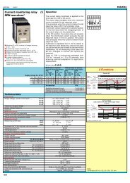
<strong>Circuit</strong> <strong>breakers</strong><br />
<strong>Thermal</strong>-<strong>magnetic</strong><br />
Alternating current<br />
Series GM<br />
DIN 3<br />
Spacing 17,6 mm (.693’’)<br />
<strong>GMU</strong>...<br />
1 pole<br />
Spacing 35,2 mm (1.39’’)<br />
<strong>GMB</strong>...<br />
2 poles<br />
Type Rating<br />
Complete the<br />
product type<br />
designation by<br />
replacing ..... with<br />
the desired current<br />
rating.<br />
For example :<br />
<strong>GMU</strong> 0.5 L<br />
<strong>GMB</strong> 10 U<br />
GMT 32 D<br />
Rated current<br />
in Amps<br />
0.1<br />
0.5<br />
1<br />
2<br />
3<br />
4<br />
6<br />
10<br />
Standard blocks. Products with other options are available,<br />
example : auxiliary contact. Consult us.<br />
Part number<br />
Curve B (1) Curve C (1) Curve D (1)<br />
<strong>GMU</strong>.....L <strong>GMU</strong>.....U <strong>GMU</strong>.....D<br />
811 112 201 811 112 301<br />
811 118 221 811 118 321<br />
811 123 221 811 123 321<br />
811 128 221 811 128 321<br />
811 132 221 811 132 321<br />
811 134 221 811 134 321<br />
811 138 201 811 138 301 811 138 401<br />
811 146 221 811 146 321 811 146 421<br />
Standard blocks. Products with other options are available,<br />
example : auxiliary contact. Consult us.<br />
Part number<br />
Curve B (1) Curve C (1) Curve D (1)<br />
<strong>GMB</strong>.....L <strong>GMB</strong>.....U <strong>GMB</strong>.....D<br />
811 212 201 811 212 301<br />
811 218 221 811 218 321<br />
811 223 221 811 223 321<br />
811 228 221 811 228 321<br />
811 232 221 811 232 321<br />
811 234 221 811 234 321<br />
811 238 201 811 238 301 811 238 401<br />
811 246 221 811 246 321 811 246 421<br />
Other ratings<br />
available,<br />
consult us.<br />
16<br />
20<br />
25<br />
32<br />
811 152 201 811 152 301 811 152 401<br />
811 156 221 811 156 321 811 156 421<br />
811 158 221 811 158 321 811 158 421<br />
811 162 201 811 162 301 811 162 401<br />
811 252 201 811 252 301 811 252 401<br />
811 256 221 811 256 321 811 256 421<br />
811 258 221 811 258 321 811 258 421<br />
811 262 201 811 262 301 811 262 401<br />
See table 1 on<br />
page 591 for<br />
current correction<br />
factor vs.<br />
temperature.<br />
: Current ratings of 0.5, 1, 2, 3, 4, 10, 20, and 25 Amps : Current ratings of 0.5, 1, 2, 3, 4, 10, 20, and 25 Amps<br />
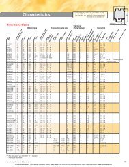
Characteristics<br />
Rated voltage<br />
V<br />
240-415 V AC, 50 - 60 Hz<br />
415 V AC, 50 - 60 Hz<br />
Rated wire size AWG / mm²<br />
Interrupting capacity<br />
According to standard NF-EN 60 898<br />
According to standard I.E.C. 947-2<br />
screw clamp for 5 AWG (16 mm²)<br />
6 000 Amps<br />
10 000 Amps<br />
screw clamp for 5 AWG (16 mm²)<br />
6 000 Amps<br />
10 000 Amps<br />
Other characteristics<br />
Life, number of cycles (On+Off)<br />
Dielectric withstanding voltage<br />
Internal resistance<br />
Tripping curves<br />
Degree of protection<br />
Weight<br />
Mechanical shock<br />
S<br />
4 000<br />
2 000 V rms<br />
See table 2 on page 591<br />
Curve B : 3 In < S < 5 In - Curve C : 5 In < S < 10 In - Curve D : 10 In < S < 20 In<br />
IP 20<br />
.21 lb (94 gr.)<br />
30 g.<br />
4 000<br />
2 000 V rms<br />
See table 2 on page 591<br />
Curve B : 3 In < S < 5 In - Curve C : 5 In < S < 10 In - Curve D : 10 In < S < 20 In<br />
IP 20<br />
.42 lb (188 gr.)<br />
30 g.<br />
Ambient temperature<br />
Connection<br />
-5° C to 40° C<br />
Ø 4,5 mm max.<br />
-5° C to 40° C<br />
Ø 4,5 mm max.<br />
Accessories<br />
Adaptor for DIN 1 rail mount<br />
Type<br />
Part number<br />
A466 822A 466 01<br />
Type<br />
Part number<br />
A466 822A 466 01<br />
Note: (1) See Curves on pages 591 and 604.
S01003 010103<br />
Spacing 52,8 mm (2.08’’)<br />
GMT...<br />
3 poles<br />
Spacing 70,4 mm (2.77’’)<br />
GMQ...<br />
4 poles<br />
Table 1<br />
Current correction<br />
factor vs. temperature<br />
Ambient Correction<br />
temperature<br />
factor<br />
°C °F (multiply by)<br />
- 20 - 4 1.25<br />
- 10 + 14 1.20<br />
- 5 + 23 1.17<br />
- 0 + 32 1.15<br />
+ 10 + 50 1.10<br />
+ 20 + 68 1.05<br />
+ 30 + 86 1.00<br />
+ 40 + 104 0.95<br />
+ 50 + 122 0.90<br />
+ 60 + 140 0.85<br />
+ 70 + 158 0.80<br />
Standard blocks. Products with other options are available,<br />
example : auxiliary contact. Consult us.<br />
Part number<br />
Curve B Curve C Curve D<br />
GMT.....L GMT.....U GMT.....D<br />
811 312 201 811 312 301<br />
811 318 221 811 318 321<br />
811 323 221 811 323 321<br />
811 328 221 811 328 321<br />
811 332 221 811 332 321<br />
811 334 221 811 334 321<br />
811 338 201 811 338 301 811 338 401<br />
811 346 221 811 346 321 811 346 421<br />
811 352 201 811 352 301 811 352 401<br />
811 356 221 811 356 321 811 356 421<br />
811 358 221 811 358 321 811 358 421<br />
811 362 201 811 362 301 811 362 401<br />
Standard blocks. Products with other options are available,<br />
example : auxiliary contact. Consult us.<br />
Part number<br />
Curve B Curve C Curve D<br />
GMQ.....L GMQ.....U GMQ.....D<br />
811 412 201 811 412 301<br />
811 418 221 811 418 321<br />
811 423 221 811 423 321<br />
811 428 221 811 428 321<br />
811 432 221 811 432 321<br />
811 434 221 811 434 321<br />
811 438 201 811 438 301 811 438 401<br />
811 446 221 811 446 321 811 446 421<br />
811 452 201 811 452 301 811 452 401<br />
811 456 221 811 456 321 811 456 421<br />
811 458 221 811 458 321 811 458 421<br />
811 462 201 811 462 301 811 462 401<br />
Table 2<br />
Internal resistance<br />
vs. current rating<br />
Time in seconds<br />
Current<br />
rating<br />
(A)<br />
Internal<br />
resistance<br />
(mΩ)<br />
0.5 4 000<br />
1 1 200<br />
2 420<br />
4 160<br />
10 13<br />
20 6<br />
Curve B<br />
: Current ratings of 0.5, 1, 2, 3, 4, 10, 20, and 25 Amps : Current ratings of 0.5, 1, 2, 3, 4, 10, 20, and 25 Amps<br />
415 V AC, 50 - 60 Hz<br />
415 V AC, 50 - 60 Hz<br />
Multiples of In (rating)<br />
Curve C<br />
screw clamp for 5 AWG (16 mm²)<br />
screw clamp for 5 AWG (16 mm²)<br />
6 000 Amps<br />
10 000 Amps<br />
6 000 Amps<br />
10 000 Amps<br />
Time in seconds<br />
Multiples of In (rating)<br />
4 000<br />
2 000 V rms<br />
See table 2<br />
Curve B : 3 In < S < 5 In - Curve C : 5 In < S < 10 In - Curve D : 10 In < S < 20 In<br />
IP 20<br />
.62 lb (282 gr.)<br />
30 g.<br />
-5° C to 40° C<br />
Ø 4,5 mm max.<br />
4 000<br />
2 000 V rms<br />
See table 2<br />
Curve B : 3 In < S < 5 In - Curve C : 5 In < S < 10 In - Curve D : 10 In < S < 20 In<br />
IP 20<br />
.83 lb (376 gr.)<br />
30 g.<br />
-5° C to 40° C<br />
Ø 4,5 mm max.<br />
Time in seconds<br />
Curve D<br />
Type Part number Type Part number<br />
ADAPTATEUR<br />
A466 822A 466 A466 01 A466 ADAPTATEUR<br />
822A 466 A466 01<br />
PXXX 123 456 78 PXXX 123 456 78<br />
Multiples of In (rating)<br />
See page 604 for larger scale curves.<br />
591
592<br />
S01004 010103<br />
<strong>Circuit</strong> <strong>breakers</strong><br />
<strong>Thermal</strong>-<strong>magnetic</strong><br />
Alternating current<br />
Series GM<br />
DIN 3<br />
Spacing 35.2 mm (1.39’’)<br />
GM1+N...<br />
1 pole + neutral<br />
Spacing 70.4 mm (2.77’’)<br />
GM3+N...<br />
3 poles + neutral<br />
Type Rating<br />
Complete the<br />
product type<br />
designation by<br />
replacing ..... with<br />
the desired current<br />
rating.<br />
For example :<br />
GM1+N 0.5 L<br />
GM1+N 10 U<br />
GM3+N 32 D<br />
Rated current<br />
in Amps<br />
0.1<br />
0.5<br />
1<br />
2<br />
3<br />
4<br />
6<br />
10<br />
Standard blocks. Products with other options are available,<br />
example : auxiliary contact. Consult us.<br />
Part number<br />
Curve B (1) Curve C (1) Curve D (1)<br />
GM1+N.....L GM1+N.....U GM1 +N.....D<br />
811 512 201 811 512 301<br />
811 518 201 811 518 301<br />
811 523 201 811 523 301<br />
811 528 201 811 528 301<br />
811 532 201 811 532 301<br />
811 534 201 811 534 301<br />
811 538 201 811 538 301 811 538 401<br />
811 546 201 811 546 301 811 546 401<br />
Standard blocks. Products with other options are available,<br />
example : auxiliary contact. Consult us.<br />
Part number<br />
Curve B (1) Curve C (1) Curve D (1)<br />
GM3+N.....L GM3+N.....U GM3+N.....D<br />
811 612 201 811 612 301<br />
811 618 201 811 618 301<br />
811 623 201 811 623 301<br />
811 628 201 811 628 301<br />
811 632 201 811 632 301<br />
811 634 201 811 634 301<br />
811 638 201 811 638 301 811 638 401<br />
811 646 201 811 646 301 811 646 401<br />
Other ratings<br />
available,<br />
consult us.<br />
16<br />
20<br />
25<br />
32<br />
811 552 201 811 552 301 811 552 401<br />
811 556 201 811 556 301 811 556 401<br />
811 558 201 811 558 301 811 558 401<br />
811 562 201 811 562 301 811 562 401<br />
811 652 201 811 652 301 811 652 401<br />
811 656 201 811 656 301 811 656 401<br />
811 658 201 811 658 301 811 658 401<br />
811 662 201 811 662 301 811 662 401<br />
See table 1 on<br />
page 591 for<br />
current correction<br />
factor vs.<br />
temperature.<br />
Characteristics<br />
Rated voltage<br />
V<br />
Approvals: Contact <strong>Entrelec</strong><br />
240 V AC, 50 - 60 Hz<br />
Approvals: Contact <strong>Entrelec</strong><br />
415 V AC, 50 - 60 Hz<br />
Rated wire size<br />
AWG / mm²<br />
Interrupting capacity<br />
According to standard I.E.C. 898<br />
According to standard I.E.C. 947-2<br />
screw clamp for 5 AWG (16 mm²)<br />
6 000 Amps<br />
10 000 Amps<br />
screw clamp for 5 AWG (16 mm²)<br />
6 000 Amps<br />
10 000 Amps<br />
Other characteristics<br />
Life, number of cycles (On+Off)<br />
Dielectric withstanding voltage<br />
Internal resistance<br />
Tripping curves<br />
Degree of protection<br />
Weight<br />
Mechanical shock<br />
S<br />
4 000<br />
2 000 V rms<br />
See table 2 on page 591<br />
Curve B : 3 In < S < 5 In - Curve C : 5 In < S < 10 In - Curve D : 10 In < S < 20 In<br />
IP 20<br />
.42 lb (188 gr.)<br />
30 g.<br />
4 000<br />
2 000 V rms<br />
See table 2 on page 591<br />
Curve B : 3 In < S < 5 In - Curve C : 5 In < S < 10 In - Curve D : 10 In < S < 20 In<br />
IP 20<br />
.83 lb (376 gr.)<br />
30 g.<br />
Ambient temperature<br />
Connection<br />
-5° C to 40° C<br />
Ø 4.5 mm max.<br />
-5° C to 40° C<br />
Ø 4.5 mm max.<br />
Accessories<br />
Adaptor for DIN 1 rail mount<br />
Type<br />
Part number<br />
A466 822A 466 01<br />
Type<br />
Part number<br />
A466 822A 466 01<br />
Note: (1) See Curves on pages 591 and 604.
593<br />
S01005 010103<br />
<strong>Circuit</strong> <strong>breakers</strong><br />
<strong>Thermal</strong>-<strong>magnetic</strong><br />
Alternating current<br />
Series GZ<br />
DIN 3<br />
Spacing 17,6 mm (.693’’)<br />
GZ1+N...<br />
1 pole + neutral<br />
Spacing 17,6 mm (.693’’)<br />
GZB...<br />
2 poles<br />
Standard blocks. Products with other options are available,<br />
Standard blocks. Products with other options are available,<br />
example : auxiliary contact. Consult us.<br />
example : auxiliary contact. Consult us.<br />
Type Rating Part number Part number<br />
Rated wire size AWG / mm 2 screw clamp for 5 AWG (16 mm²)<br />
screw clamp for 5 AWG (16 mm²)<br />
Complete the Rated current Curve B (1) Curve C (1) Curve D (1)<br />
Curve B (1) Curve C (1) Curve D (1)<br />
product type in Amps<br />
GZ1+N.....L GZ1+N.....U GZ1+N.....D<br />
GZB.....L GZB.....U GZB.....D<br />
designation by 0.1<br />
814 512 201 814 512 301<br />
814 212 201 814 212 301<br />
replacing ..... with 0.5<br />
814 518 201 814 518 301<br />
814 218 201 814 218 301<br />
the desired current 1<br />
814 523 201 814 523 301<br />
814 223 201 814 223 301<br />
rating.<br />
2<br />
814 528 201 814 528 301<br />
814 228 201 814 228 301<br />
For example :<br />
GZ1+N 0.5 L<br />
3<br />
814 532 201 814 532 301<br />
814 232 201 814 232 301<br />
GZ1+N 10 U<br />
4<br />
814 534 201 814 534 301<br />
814 234 201 814 234 301<br />
GZB 32 D<br />
6<br />
814 538 201 814 538 301 814 538 401 814 238 201 814 238 301 814 238 401<br />
10<br />
814 546 201 814 546 301 814 546 401 814 246 201 814 246 301 814 246 401<br />
Other ratings<br />
16<br />
814 552 201 814 552 301 814 552 401 814 252 201 814 252 301 814 252 401<br />
available,<br />
20<br />
814 556 201 814 556 301 814 556 401 814 256 201 814 256 301 814 256 401<br />
consult us.<br />
25<br />
814 558 201 814 558 301 814 558 401 814 258 201 814 258 301 814 258 401<br />
32<br />
814 562 201 814 562 301 814 562 401 814 262 201 814 262 301 814 262 401<br />
See table 1 on<br />
page 591 for<br />
current correction<br />
factor vs.<br />
temperature.<br />
Approvals: Contact <strong>Entrelec</strong><br />
Approvals: Contact <strong>Entrelec</strong><br />
Characteristics<br />
Rated voltage V<br />
240 V AC, 50 - 60 Hz<br />
415 V AC, 50 - 60 Hz<br />
Interrupting capacity<br />
According to standard NF-EN 60 898<br />
According to standard IEC 947-2<br />
3 000 Amps<br />
4 500 Amps<br />
4 500 Amps<br />
6 000 Amps<br />
Other characteristics<br />
Life, number of cycles (On+Off)<br />
Dielectric withstanding voltage<br />
Internal resistance<br />
Tripping curves<br />
Degree of protection<br />
Weight<br />
Mechanical shock<br />
Ambient temperature<br />
Connection<br />
S<br />
4 000<br />
2 000 V rms<br />
See table 2 on page 591<br />
Curve B : 3 In < S < 5 In - Curve C : 5 In < S < 10 In - Curve D : 10 In < S < 20 In<br />
IP 20<br />
.22 lb (99 gr.)<br />
30 g.<br />
-5° C to 40° C<br />
Ø 4.5 mm max.<br />
4 000<br />
2 000 V rms<br />
See table 2 on page 591<br />
Curve B : 3 In < S < 5 In - Curve C : 5 In < S < 10 In - Curve D : 10 In < S < 20 In<br />
IP 20<br />
.24 lb (110 gr.)<br />
30 g.<br />
-5° C to 40° C<br />
Ø 4.5 mm max.<br />
Accessories<br />
Adaptor for DIN 1 rail mount<br />
Type<br />
Part number Type<br />
Part number<br />
A466 822A 466 01 A466 822A 466 01<br />
Note: (1) See Curves on pages 591 and 604.
594<br />
S01006 010103<br />
<strong>Circuit</strong> <strong>breakers</strong><br />
<strong>Thermal</strong><br />
Alternating current<br />
Series GM<br />
DIN 3<br />
Spacing 17,6 mm (.693’’)<br />
<strong>GMU</strong>...T<br />
1 pole<br />
Spacing 35,2 mm (1.39’’)<br />
<strong>GMB</strong>...T<br />
2 poles<br />
Type<br />
Other ratings<br />
available,<br />
consult us.<br />
See table 1 on<br />
page 595 for<br />
current correction<br />
factor vs.<br />
temperature.<br />
Rated current<br />
in Amps<br />
0.1<br />
0.5<br />
1<br />
2<br />
3<br />
4<br />
6<br />
10<br />
Standard blocks. Products with other options are available,<br />
example : auxiliary contact. Consult us.<br />
<strong>GMU</strong> 0.1T 811 112 601<br />
<strong>GMU</strong> 0.5 T 811 118 620<br />
<strong>GMU</strong> 1 T 811 123 620<br />
<strong>GMU</strong> 2 T 811 128 620<br />
<strong>GMU</strong> 3 T 811 132 620<br />
<strong>GMU</strong> 4 T 811 134 620<br />
<strong>GMU</strong> 6 T 811 138 601<br />
<strong>GMU</strong> 10 T 811 146 620<br />
Standard blocks. Products with other options are available,<br />
example : auxiliary contact. Consult us.<br />
Type Part number Type Part number<br />
Curve T (1)<br />
Curve T (1)<br />
<strong>GMB</strong> 0.1T 811 212 601<br />
<strong>GMB</strong> 0.5 T 811 218 620<br />
<strong>GMB</strong> 1 T 811 223 620<br />
<strong>GMB</strong> 2 T 811 228 620<br />
<strong>GMB</strong> 3 T 811 232 620<br />
<strong>GMB</strong> 4 T 811 234 620<br />
<strong>GMB</strong> 6 T 811 238 601<br />
<strong>GMB</strong> 10 T 811 246 620<br />
16<br />
20<br />
25<br />
32<br />
<strong>GMU</strong> 16 T 811 152 601<br />
<strong>GMU</strong> 20 T 811 156 620<br />
<strong>GMU</strong> 25 T 811 158 620<br />
<strong>GMU</strong> 32 T 811 162 601<br />
<strong>GMB</strong> 16 T 811 252 601<br />
<strong>GMB</strong> 20 T 811 256 620<br />
<strong>GMB</strong> 25 T 811 258 620<br />
<strong>GMB</strong> 32 T 811 262 601<br />
: Current ratings of 0.5, 1, 2, 3, 4, 10, 20, and 25 Amps<br />
: Current ratings of 0.5, 1, 2, 3, 4, 10, 20, and 25 Amps<br />
Characteristics<br />
Rated voltage<br />
240-415 V AC, 50 - 60 Hz<br />
415 V AC, 50 - 60 Hz<br />
Rated wire size<br />
AWG / mm²<br />
Interrupting capacity<br />
Curve T<br />
screw clamp for 5 AWG (16 mm²)<br />
screw clamp for 5 AWG (16 mm²)<br />
10 In Rating < 5 Amps - 20 In Rating ≥ 5 Amps 10 In Rating < 5 Amps - 20 In Rating ≥ 5 Amps<br />
Other characteristics<br />
Life, number of cycles (On+Off)<br />
Dielectric withstanding voltage<br />
Internal resistance<br />
Tripping curves<br />
Degree of protection<br />
Weight<br />
Mechanical shock<br />
Ambient temperature<br />
Connection<br />
4 000<br />
2 000 V rms<br />
See table 3 on page 595<br />
IP 20<br />
.2 lb (87 gr.)<br />
30 g.<br />
-5° C to 40° C<br />
Ø 4.5 mm max.<br />
4 000<br />
2 000 V rms<br />
See table 3 on page 595<br />
IP 20<br />
.38 lb (174 gr.)<br />
30 g.<br />
-5° C to 40° C<br />
Ø 4.5 mm max.<br />
Accessories<br />
Adaptor for DIN 1 rail mount<br />
Type<br />
Part number Type<br />
Part number<br />
A466 822A 466 01 A466 822A 466 01<br />
Note: (1) See Curves on pages 595 and 605.
595<br />
S01007 010103<br />
Spacing 52,8 mm (2.08’’)<br />
GMT...T<br />
3 poles<br />
Spacing 70,4 mm (2.77’’)<br />
GMQ...T<br />
4 poles<br />
Table 1<br />
Current correction<br />
factor vs. temperature<br />
Ambient Correction<br />
temperature<br />
factor<br />
°C °F (multiply by)<br />
- 20 - 4 1.25<br />
- 10 + 14 1.20<br />
- 5 + 23 1.17<br />
- 0 + 32 1.15<br />
+ 10 + 50 1.10<br />
+ 20 + 68 1.05<br />
+ 30 + 86 1.00<br />
+ 40 +104 0.95<br />
+ 50 +122 0.90<br />
+ 60 +140 0.85<br />
+ 70 +158 0.80<br />
Standard blocks. Products with other options are available,<br />
example : auxiliary contact. Consult us.<br />
GMT 0.1T 811 312 601<br />
GMT 0.5 T 811 318 620<br />
GMT 1 T 811 323 620<br />
GMT 2 T 811 328 620<br />
GMT 3 T 811 332 620<br />
GMT 4 T 811 334 620<br />
GMT 6 T 811 338 601<br />
GMT 10 T 811 346 620<br />
Standard blocks. Products with other options are available,<br />
example : auxiliary contact. Consult us.<br />
Type Part number Type Part number<br />
Curve T (1) Curve T (1)<br />
GMQ 0.1T 811 412 601<br />
GMQ 0.5 T 811 418 620<br />
GMQ 1 T 811 423 620<br />
GMQ 2 T 811 428 620<br />
GMQ 3 T 811 432 620<br />
GMQ 4 T 811 434 620<br />
GMQ 6 T 811 438 601<br />
GMQ 10 T 811 446 620<br />
Table 3<br />
Current<br />
rating<br />
(A)<br />
Internal resistance<br />
vs. current rating<br />
Internal<br />
resistance<br />
(mΩ)<br />
0.5 3 000<br />
1 1 000<br />
2 350<br />
4 130<br />
10 10<br />
20 5<br />
Curve T<br />
GMT 16 T 811 352 601<br />
GMT 20 T 811 356 620<br />
GMT 25 T 811 358 620<br />
GMT 32 T 811 362 601<br />
GMQ 16 T 811 452 601<br />
GMQ 20 T 811 456 620<br />
GMQ 25 T 811 458 620<br />
GMQ 32 T 811 462 601<br />
: Current ratings of 0.5, 1, 2, 3, 4, 10, 20, and 25 Amps : Current ratings of 0.5, 1, 2, 3, 4, 10, 20, and 25 Amps<br />
415 V AC, 50 - 60 Hz<br />
screw clamp for 5 AWG (16 mm²)<br />
415 V AC, 50 - 60 Hz<br />
screw clamp for 5 AWG (16 mm²)<br />
See page 605 for larger scale curve.<br />
10 In Rating < 5 Amps - 20 In Rating ≥ 5 Amps<br />
10 In Rating < 5 Amps - 20 In Rating ≥ 5 Amps<br />
4 000<br />
2 000 V rms<br />
See table 3<br />
IP 20<br />
.58 lb (261 gr.)<br />
30 g.<br />
-5° C to 40° C<br />
Ø 4.5 mm max.<br />
4 000<br />
2 000 V rms<br />
See table 3<br />
IP 20<br />
.77 lb (348 gr.)<br />
30 g.<br />
-5° C to 40° C<br />
Ø 4.5 mm max.<br />
Type Part number Type Part number<br />
ADAPTATEUR<br />
A466 ADAPTATEUR 822A 466 01 A466 A466<br />
822A 466 01<br />
A466<br />
PXXX 123 456 78
596<br />
S01008 010103<br />
<strong>Circuit</strong> <strong>breakers</strong><br />
<strong>Thermal</strong>-<strong>magnetic</strong><br />
Direct current<br />
100 V max.<br />
Series GF<br />
DIN 3<br />
Spacing 17,6 mm (.693’’)<br />
GFU...S<br />
1 pole<br />
Spacing 35,2 mm (1.39’’)<br />
GFB...S<br />
2 poles<br />
Rating<br />
Other ratings<br />
available,<br />
consult us.<br />
Rated current<br />
in Amps<br />
0.1<br />
0.5<br />
1<br />
2<br />
Standard blocks. Products with other options are available,<br />
example : auxiliary contact. Consult us.<br />
Type<br />
Part number<br />
GFU 0.1 S 812 112 501<br />
GFU 0.5 S 812 118 501<br />
GFU 1 S 812 123 501<br />
GFU 2 S 812 128 501<br />
Standard blocks. Products with other options are available,<br />
example : auxiliary contact. Consult us.<br />
Type<br />
Part number<br />
GFB 0.1 S 812 212 501<br />
GFB 0.5 S 812 218 501<br />
GFB 1 S 812 223 501<br />
GFB 2 S 812 228 501<br />
3<br />
4<br />
6<br />
10<br />
GFU 3 S 812 132 501<br />
GFU 4 S 812 134 501<br />
GFU 6 S 812 138 501<br />
GFU 10 S 812 146 501<br />
GFB 3 S 812 232 501<br />
GFB 4 S 812 234 501<br />
GFB 6 S 812 238 501<br />
GFB 10 S 812 246 501<br />
16<br />
20<br />
25<br />
32<br />
GFU 16 S 812 152 501<br />
GFU 20 S 812 156 501<br />
GFU 25 S 812 158 501<br />
GFU 32 S 812 162 501<br />
GFB 16 S 812 252 501<br />
GFB 20 S 812 256 501<br />
GFB 25 S 812 258 501<br />
GFB 32 S 812 262 501<br />
Characteristics<br />
Rated voltage<br />
V<br />
Approvals: Contact <strong>Entrelec</strong><br />
100 V DC max.<br />
Approvals: Contact <strong>Entrelec</strong><br />
100 V DC max.<br />
Rated wire size<br />
AWG / mm²<br />
Interrupting capacity<br />
According to standard NF F62 001<br />
screw clamp for 5 AWG (16 mm²)<br />
screw clamp for 5 AWG (16 mm²)<br />
1 000 Amps 1 000 Amps<br />
Other characteristics<br />
Life, number of cycles (On+Off)<br />
Dielectric withstanding voltage<br />
Internal resistance<br />
Tripping curves<br />
Degree of protection<br />
Weight<br />
Mechanical shock<br />
V<br />
S<br />
4 000<br />
2 000 V rms<br />
See table 2 on page 591<br />
Current rating 0.1 to 2 A : 5 In < S < 10 In - 3 to 32 A : 7 In < S < 14 In<br />
IP 20<br />
.21 lb (94 gr.)<br />
30 g.<br />
4 000<br />
2 000 V rms<br />
See table 2 on page 591<br />
Current rating 0.1 to 2 A : 5 In < S < 10 In - 3 to 32 A : 7 In < S < 14 In<br />
IP 20<br />
.42 lb (188 gr.)<br />
30 g.<br />
Ambient temperature<br />
Connection<br />
- 25° C to + 70° C<br />
Ø 4.5 mm max.<br />
- 25° C to + 70° C<br />
Ø 4.5 mm max.<br />
Accessories<br />
Adaptor for DIN 1 rail mount<br />
Type<br />
Part number Type<br />
Part number<br />
A466 822A 466 01 A466 822A 466 01
597<br />
S01009 010103<br />
<strong>Circuit</strong> <strong>breakers</strong><br />
<strong>Thermal</strong>-<strong>magnetic</strong><br />
Direct current<br />
150 V max.<br />
Series GC<br />
DIN 3<br />
Spacing 17,6 mm (.693)<br />
GCU...S<br />
1 pole<br />
Spacing 35,2 mm (1.39’’)<br />
GCB...S<br />
2 poles<br />
Rating<br />
Other ratings<br />
available,<br />
consult us.<br />
Rated current<br />
in Amps<br />
0.1<br />
0.5<br />
1<br />
2<br />
Standard blocks. Products with other options are available,<br />
example : auxiliary contact. Consult us.<br />
Type<br />
Part number<br />
GCU 0.1 S 813 112 501<br />
GCU 0.5 S 813 118 501<br />
GCU 1 S 813 123 501<br />
GCU 2 S 813 128 501<br />
Standard blocks. Products with other options are available,<br />
example : auxiliary contact. Consult us.<br />
Type<br />
Part number<br />
GCB 0.1 S 813 212 501<br />
GCB 0.5 S 813 218 501<br />
GCB 1 S 813 223 501<br />
GCB 2 S 813 228 501<br />
3<br />
4<br />
6<br />
10<br />
GCU 3 S 813 132 501<br />
GCU 4 S 813 134 501<br />
GCU 6 S 813 138 501<br />
GCU 10 S 813 146 501<br />
GCB 3 S 813 232 501<br />
GCB 4 S 813 234 501<br />
GCB 6 S 813 238 501<br />
GCB 10 S 813 246 501<br />
16<br />
20<br />
25<br />
32<br />
GCU 16 S 813 152 501<br />
GCU 20 S 813 156 501<br />
GCU 25 S 813 158 501<br />
GCU 32 S 813 162 501<br />
GCB 16 S 813 252 501<br />
GCB 20 S 813 256 501<br />
GCB 25 S 813 258 501<br />
GCB 32 S 813 262 501<br />
Characteristics<br />
Rated voltage<br />
V<br />
Approvals: Contact <strong>Entrelec</strong><br />
150 V DC max.<br />
Approvals: Contact <strong>Entrelec</strong><br />
150 V DC max.<br />
Rated wire size AWG / mm²<br />
Interrupting capacity<br />
According to standard NF F62 001<br />
screw clamp for 5 AWG (16 mm²)<br />
screw clamp for 5 AWG (16 mm²)<br />
1 500 Amps 1 500 Amps<br />
Other characteristics<br />
Life, number of cycles (On+Off)<br />
Dielectric withstanding voltage<br />
Internal resistance<br />
Tripping curves<br />
Degree of protection<br />
Weight<br />
Mechanical shock<br />
Ambient temperature<br />
Connection<br />
V<br />
S<br />
4 000<br />
2 000 V rms<br />
See table 2 on page 591<br />
Current rating 0.1 to 2 A : 5 In < S < 10 In - 3 to 32 A : 7 In < S < 14 In<br />
IP 20<br />
.21 lb (94 gr.)<br />
30 g.<br />
- 25° C to + 70° C<br />
Ø 4.5 mm max.<br />
4 000<br />
2 000 V rms<br />
See table 2 on page 591<br />
Current rating 0.1 to 2 A : 5 In < S < 10 In - 3 to 32 A : 7 In < S < 14 In<br />
IP 20<br />
.42 lb (188 gr.)<br />
30 g.<br />
- 25° C to + 70° C<br />
Ø 4.5 mm max.<br />
Accessories<br />
Adaptor for DIN 1 rail mount<br />
Type<br />
Part number Type<br />
Part number<br />
A466 822A 466 01 A466 822A 466 01
598<br />
S01010 010103<br />
<strong>Circuit</strong> <strong>breakers</strong><br />
<strong>Thermal</strong><br />
Direct current<br />
100 V max.<br />
Series GF<br />
DIN 3<br />
Spacing 17,6 mm (0.693’’)<br />
GFU...T<br />
1 pole<br />
Spacing 35,2 mm (1.39’’)<br />
GFB...T<br />
2 poles<br />
Type<br />
Other ratings<br />
available,<br />
consult us.<br />
See table 1 on<br />
page 595 for<br />
current correction<br />
factor vs.<br />
temperature.<br />
Rated current<br />
in Amps<br />
0.1<br />
0.5<br />
1<br />
2<br />
3<br />
4<br />
6<br />
10<br />
Standard blocks. Products with other options are available,<br />
example : auxiliary contact. Consult us.<br />
GFU 0.1 T 812 112 601<br />
GFU 0.5 T 812 118 601<br />
GFU 1 T 812 123 601<br />
GFU 2 T 812 128 601<br />
GFU 3 T 812 132 601<br />
GFU 4 T 812 134 601<br />
GFU 6 T 812 138 601<br />
GFU 10 T 812 146 601<br />
Standard blocks. Products with other options are available,<br />
example : auxiliary contact. Consult us.<br />
Type Part number Type Part number<br />
Curve T (1)<br />
Curve T (1)<br />
GFB 0.1 T 812 212 601<br />
GFB 0.5 T 812 218 601<br />
GFB 1 T 812 223 601<br />
GFB 2 T 812 228 601<br />
GFB 3 T 812 232 601<br />
GFB 4 T 812 234 601<br />
GFB 6 T 812 238 601<br />
GFB 10 T 812 246 601<br />
16<br />
20<br />
25<br />
32<br />
GFU 16 T 812 152 601<br />
GFU 20 T 812 156 601<br />
GFU 25 T 812 158 601<br />
GFU 32 T 812 162 601<br />
GFB 16 T 812 252 601<br />
GFB 20 T 812 256 601<br />
GFB 25 T 812 258 601<br />
GFB 32 T 812 262 601<br />
Characteristics<br />
Rated voltage<br />
V<br />
Approvals: Contact <strong>Entrelec</strong><br />
Approvals: Contact <strong>Entrelec</strong><br />
100 V DC max. 100 V DC max.<br />
Rated wire size<br />
AWG / mm²<br />
Interrupting capacity<br />
Curve T<br />
10 In Rating < 5 Amps - 20 In Rating ≥ 5 Amps 10 In Rating < 5 Amps - 20 In Rating ≥ 5 Amps<br />
Other characteristics<br />
Life, number of cycles (On+Off)<br />
Dielectric withstanding voltage<br />
Internal resistance<br />
Degree of protection<br />
Weight<br />
Mechanical shock<br />
Ambient temperature<br />
Connection<br />
4 000<br />
2 000 V rms<br />
See table 3 on page 595<br />
IP 20<br />
.2 lb (87 gr.)<br />
30 g.<br />
- 5° C to 40° C<br />
Ø 4.5 mm. max.<br />
4 000<br />
2 000 V rms<br />
See table 3 on page 595<br />
IP 20<br />
.38 lb (174 gr.)<br />
30 g.<br />
-5° C to 40° C<br />
Ø 4.5 mm. max.<br />
Accessories<br />
Adaptor for DIN 1 rail mount<br />
Type<br />
Part number Type<br />
Part number<br />
A466 822A 466 01 A466 822A 466 01<br />
Note: (1) See Curves on pages 595 and 605.
599<br />
S01011 010103<br />
<strong>Circuit</strong> <strong>breakers</strong><br />
<strong>Thermal</strong><br />
Direct current<br />
150 V max.<br />
Series GC<br />
DIN 3<br />
Spacing 17,6 mm (0.693’’)<br />
GCU...T<br />
1 pole<br />
Spacing 35,2 mm (1.39’’)<br />
GCB...T<br />
2 poles<br />
Type<br />
Other ratings<br />
available,<br />
consult us.<br />
See table 1 on<br />
page 595 for<br />
current correction<br />
factor vs.<br />
temperature.<br />
Rated current<br />
in Amps<br />
0.1<br />
0.5<br />
1<br />
2<br />
3<br />
4<br />
6<br />
10<br />
Standard blocks. Products with other options are available,<br />
example : auxiliary contact. Consult us.<br />
GCU 0.1 T 813 112 601<br />
GCU 0.5 T 813 118 601<br />
GCU 1 T 813 123 601<br />
GCU 2 T 813 128 601<br />
GCU 3 T 813 132 601<br />
GCU 4 T 813 134 601<br />
GCU 6 T 813 138 601<br />
GCU 10 T 813 146 601<br />
Standard blocks. Products with other options are available,<br />
example : auxiliary contact. Consult us.<br />
Type Part number Type Part number<br />
Curve T (1)<br />
Curve T (1)<br />
GCB 0.1 T 813 212 601<br />
GCB 0.5 T 813 218 601<br />
GCB 1 T 813 223 601<br />
GCB 2 T 813 228 601<br />
GCB 3 T 813 232 601<br />
GCB 4 T 813 234 601<br />
GCB 6 T 813 238 601<br />
GCB 10 T 813 246 601<br />
16<br />
20<br />
25<br />
32<br />
GCU 16 T 813 152 601<br />
GCU 20 T 813 156 601<br />
GCU 25 T 813 158 601<br />
GCU 32 T 813 162 601<br />
GCB 16 T 813 252 601<br />
GCB 20 T 813 256 601<br />
GCB 25 T 813 258 601<br />
GCB 32 T 813 262 601<br />
Characteristics<br />
Rated voltage<br />
V<br />
Approvals: Contact <strong>Entrelec</strong><br />
Approvals: Contact <strong>Entrelec</strong><br />
150 V DC max. 150 V DC max.<br />
Rated wire size AWG / mm²<br />
Interrupting capacity<br />
Curve T<br />
10 In Rating < 5 Amps - 20 In Rating ≥ 5 Amps 10 In Rating < 5 Amps - 20 In Rating ≥ 5 Amps<br />
Other characteristics<br />
Life, number of cycles (On+Off)<br />
Dielectric withstanding voltage<br />
Internal resistance<br />
Degree of protection<br />
Weight<br />
Mechanical shock<br />
Ambient temperature<br />
Connection<br />
4 000<br />
2 000 V rms<br />
See table 3 on page 595<br />
IP 20<br />
.2 lb (87 gr.)<br />
30 g.<br />
- 5° C to 40° C<br />
Ø 4.5 mm. max.<br />
4 000<br />
2 000 V rms<br />
See table 3 on page 595<br />
IP 20<br />
.38 lb (174 gr.)<br />
30 g.<br />
-5° C to 40° C<br />
Ø 4.5 mm. max.<br />
Accessories<br />
Adaptor for DIN 1 rail mount<br />
Type<br />
Part number Type<br />
Part number<br />
A466 822A 466 01 A466 822A 466 01<br />
Note: (1) See Curves on pages 595 and 605.
600<br />
S01015 010103<br />
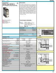
<strong>Circuit</strong> <strong>breakers</strong><br />
Earth leakage device<br />
<strong>Thermal</strong>-<strong>magnetic</strong><br />
Alternating current<br />
Series DDI<br />
DIN 3<br />
Spacing 35 mm (1.38’’)<br />
DDI1+N...C...<br />
1 pole + neutral in 2 modules<br />
Spacing 52,5 mm (2.07)<br />
DDIB...C...<br />
2 poles protected in 3 modules<br />
Type Rating<br />
Complete the<br />
product type<br />
designation by<br />
replacing ..... with<br />
the desired current<br />
rating.<br />
For example :<br />
DDI1+N 6 C 0.03<br />
DDI1+N 10 C 0.01<br />
DDIB 25 C 0.3<br />
Other ratings<br />
available,<br />
consult us.<br />
Curve :<br />
Type :<br />
Sensitivity :<br />
Rated current<br />
in Amps<br />
6<br />
10<br />
16<br />
20<br />
25<br />
32<br />
40<br />
Standard blocks. Products with other options are available.<br />
Consult us.<br />
Part number<br />
Curve C (1) Curve C (1) Curve C (1) Curve C (1) Curve C (1) Curve C (1)<br />
DDI1+N...C0.01 DDI1+N...C0.03 DDI1+N...C0.3 DDIB...C0.01 DDIB...C0.03 DDIB...C0.3<br />
10 mA 30 mA 300 mA<br />
10 mA 30 mA 300 mA<br />
863 538 311 863 538 321 863 538 341<br />
863 546 311 863 546 321 863 546 341<br />
863 552 311 863 552 321 863 552 341<br />
863 556 321 863 556 341<br />
863 558 321 863 558 341<br />
863 562 321 863 562 341<br />
863 566 321 863 566 341<br />
Standard blocks. Products with other options are available.<br />
Consult us.<br />
Part number<br />
863 238 311 863 238 321 863 238 341<br />
863 246 311 863 246 321 863 246 341<br />
863 252 311 863 252 321 863 252 341<br />
863 256 321 863 256 341<br />
863 258 321 863 258 341<br />
863 262 321 863 262 341<br />
863 266 321 863 266 341<br />
Approvals: Contact <strong>Entrelec</strong><br />
Approvals: Contact <strong>Entrelec</strong><br />
Characteristics<br />
Rated voltage<br />
V<br />
240 V AC, 50/60 Hz<br />
240 V AC, 50/60 Hz<br />
Rated wire size<br />
AWG / mm²<br />
Interrupting capacity<br />
According to standard I.E.C. 1 009 - 1<br />
screw clamp for 3 AWG (25 mm²)<br />
6 000 Amps<br />
screw clamp for 3 AWG (25 mm²)<br />
6 000 Amps (10 000 Amps on request)<br />
Curve C (1)<br />
Other characteristics<br />
Life, number of cycles (On+Off)<br />
Dielectric withstanding voltage<br />
4 000<br />
2 000 V rms<br />
4 000<br />
2 000 V rms<br />
Tripping curves<br />
Degree of protection<br />
Weight<br />
Mechanical shock<br />
S<br />
5 In < S < 10 In<br />
IP 20<br />
.49 lb (220 gr.)<br />
30 g.<br />
Time in seconds<br />
5 In < S < 10 In<br />
IP 20<br />
.72 lb (325 gr.)<br />
30 g.<br />
Ambient temperature<br />
-5° C to 40° C<br />
-5° C to 40° C<br />
Multiples of In (rating)<br />
Accessories<br />
Adaptor for DIN 1 rail mount<br />
Type<br />
Part number Type<br />
Part number<br />
A466 822A 466 01 A466 822A 466 01<br />
Note: (1) See page 604 for larger scale curves.
601<br />
S01013 010103<br />
DDI3+N<br />
3 poles protected + neutral in 4<br />
Spacing 52,8 mm (2.08’’)<br />
Table 1<br />
Current correction<br />
factor vs. temperature<br />
Ambient Correction<br />
temperature<br />
factor<br />
°C °F (multiply by)<br />
- 20 - 4 1.25<br />
- 10 + 14 1.20<br />
- 5 + 23 1.17<br />
- 0 + 32 1.15<br />
+ 10 + 50 1.10<br />
+ 20 + 68 1.05<br />
+ 30 + 86 1.00<br />
+ 40 + 104 0.95<br />
+ 50 + 122 special P/N<br />
+ 60 + 140 special P/N<br />
+ 70 + 158 special P/N<br />
Standard blocks. Products with other options are available,<br />
example : auxiliary contact. Consult us.<br />
Part number<br />
Curve C<br />
DDI3+N...C0.01 DDI3+N...C0.03 DDI3+N...C0.3<br />
10 mA 30 mA 300 mA<br />
863 638 311 863 638 321 863 638 341<br />
863 646 311 863 646 321 863 646 341<br />
863 652 311 863 652 321 863 652 341<br />
863 656 311 863 656 321 863 656 341<br />
863 658 311 863 658 321 863 658 341<br />
863 662 311 863 662 321 863 662 341<br />
863 666 311 863 666 321 863 666 341<br />
Table 2<br />
Internal resistance<br />
vs. current rating<br />
Current<br />
rating<br />
(A)<br />
Curve C<br />
Internal<br />
resistance<br />
(mΩ)<br />
0.5 4 000<br />
1 1 200<br />
2 420<br />
4 160<br />
10 13<br />
20 6<br />
Time in seconds<br />
Multiples of In (rating)<br />
Approvals: Contact <strong>Entrelec</strong><br />
415 V AC, 50 - 60 Hz<br />
See page 604 for larger scale curves.<br />
screw clamp for 3 AWG (25 mm²)<br />
6 000 Amps<br />
4 000<br />
2 000 V rms<br />
5 In < S < 10 In<br />
IP 20<br />
.58 lb (261 gr.)<br />
30 g.<br />
-5° C to 40° C<br />
Type<br />
Part number<br />
A466 ADAPTATEUR 822A 466 01<br />
A466
602<br />
S01014 010103<br />
Switches<br />
Earth leakage device<br />
Alternating current<br />
Series IDI<br />
DIN 3<br />
Spacing 35 mm (1.38’’)<br />
IDIB...N...<br />
2 poles<br />
Spacing 70 mm (2.76’’)<br />
IDIQ...N...<br />
4 poles<br />
Poles<br />
N° 1 N° 2 N° 3 N° 4<br />
Type Rating<br />
Complete the<br />
product type<br />
designation by<br />
replacing ..... with<br />
the desired current<br />
rating.<br />
For example :<br />
IDIB 25 N 0.03<br />
IDIQ 40 N 0.3<br />
Type :<br />
Sensitivity :<br />
Rated current<br />
in Amps<br />
25<br />
40<br />
Standard blocks. Products with other options are available.<br />
Consult us.<br />
Part number<br />
IDIB... N 0.03 IDIB... N 0.3<br />
30 mA 300 mA<br />
861 258 721 861 258 741<br />
861 266 721 861 266 741<br />
Standard blocks. Products with other options are available.<br />
Consult us.<br />
Part number<br />
IDIQ.....N 0.03 IDIQ.....N 0.3<br />
30 mA 300 mA<br />
861 458 721 861 458 741<br />
861 466 721 861 466 741<br />
Other ratings<br />
available,<br />
consult us.<br />
Characteristics<br />
Rated voltage<br />
V<br />
Approvals: Contact <strong>Entrelec</strong><br />
240 V AC, 50/60 Hz<br />
Approvals: Contact <strong>Entrelec</strong><br />
415 V AC, 50/60 Hz<br />
Rated wire size<br />
AWG / mm²<br />
Sensitivity<br />
According to standard I.E.C. 1 008-1<br />
screw clamp for 3 AWG (25 mm²)<br />
Standard : 30 mAmps (10 mAmps, 300 mAmps)<br />
screw clamp for 3 AWG (25 mm²)<br />
Standard : 30 mAmps (10 mAmps, 300 mAmps)<br />
Other characteristics<br />
Life, number of cycles (On+Off)<br />
Dielectric withstanding voltage<br />
4 000<br />
2 000 V rms<br />
4 000<br />
2 000 V rms<br />
Degree of protection<br />
Weight<br />
Mechanical shock<br />
Ambient temperature<br />
IP 20<br />
.42 lb (190 gr.)<br />
30 g.<br />
-5° C to 40° C<br />
IP 20<br />
.75 lb (340 gr.)<br />
30 g.<br />
-5° C to 40° C<br />
Accessories<br />
Adaptor for DIN 1 rail mount<br />
Type<br />
Part number Type<br />
Part number<br />
A466 822A 466 01 A466 822A 466 01
603<br />
S01017 010103<br />
<strong>Circuit</strong> <strong>breakers</strong> Series GALAXIE : GD - GH - GN - GV – To order, see page 608<br />
Dimensions in millimeters<br />
Fastenings and operations N o 00 - 01 - 02 - 03 - 04 - 06 - 07 - 08<br />
Fastenings / Operations 00 01 02 03 04 05 06 07 08 09<br />
Size A 8 8 8 8 8 17,5 15 15 21 28<br />
Size C 32 32 32 32 32 37 32 32 32 32<br />
Pole Pole Pole Pole Pole<br />
N° 1 N° 2 N° 1 N° 2 N° 3<br />
1 Width 2 Widths 3 Widths<br />
Fastenings and operations N o 05 - 09<br />
Terminations 00 01 02 03 33 43 07 08 09<br />
Size B 15 4 4 12 4 4 4 4 11<br />
*<br />
Four-pole circuit breaker :<br />
Fastening and operation N o 05<br />
only<br />
NOTE :<br />
Neutral on pole N° 1<br />
any<br />
Fastenings and operations<br />
Pole Pole Pole Pole Pole Pole Pole Pole Pole<br />
N° 2 N° 1 N° 3 N° 2 N° 1 N° 4 N° 3 N° 2 N° 1<br />
1 Width 2 Widths 3 Widths = 1 handle 4 Widths = 2 handles<br />
Fastenings and operations (3 poles max. except 02 : 2 poles and 05 : 4 poles)<br />
P R O J E C T I O N M O U N T I N G S C R E W F L U S H M O U N T I N G Maximum thickness of mounting panel :<br />
3 mm. 3 mm. 3 mm. 6 mm. 6 mm. 6 mm. 6 mm.<br />
00 01 02 03 04 05 06 07 08 09<br />
Tightening torque :<br />
1,8 Nm max. 1,8 Nm max. 1,8 Nm max. 3 Nm max.<br />
Terminations<br />
*<br />
00 01 02 03 33 43 07 08 09<br />
16 A max. 240 A max. 16 A max. 16 A max. 16 A max.<br />
Except Fastening 08 2 poles max. 2 poles max. 2 poles max.<br />
Characteristics SERIES GD SERIES GH SERIES GN SERIES GV<br />
Rated voltage<br />
1 + neutral version<br />
One pole version<br />
Multipole version<br />
One pole and two pole version<br />
Interrupting capacity<br />
According to standard IEC 898<br />
According to standard NF F62 001<br />
Other characteristics<br />
Life, number of cycles (On+Off)<br />
Dielectric withstanding voltage<br />
UL, CSA : For list of certified products : consult us<br />
<strong>Circuit</strong> <strong>breakers</strong> NF F62 001 : consult us<br />
240 V AC (50/60 Hz)<br />
240/415 V AC (50/60 Hz) 240/415 V AC (50/60 Hz)<br />
415 V AC (50/60 Hz) 415 V AC (50/60 Hz)<br />
48 V DC max. 100 V DC max. 150 V DC max.<br />
3 000 A 4 500 A (models U and D: rating ≥ 5 A)<br />
4 500 A (model L: rating ≥ 10 A)<br />
1 000 A (48 V DC max.) 500 A 1 000 A (48 V DC max.)<br />
10 In cal. < 5 A ; 20 In cal > 5 A 10 In cal. < 5 A ; 20 In cal > 5 A 10 In cal. < 5 A ; 20 In cal > 5 A<br />
4 000 4 000 4 000 4 000<br />
2 000 V rms 2 000 V rms 2 000 V rms 2 000 V rms<br />
Tripping curves (1) (2)<br />
S<br />
Curve B : 3 In < S < 5 In - Curve C : 5 In < S < 10 In - Curve D : 10 In < S < 20 In<br />
Nominal current 0.1 to 2 A : 5 In < S < 10 In - 3 to 32 A : 7 In < S < 14 In<br />
Mechanical shock<br />
Ambient temperature<br />
30 g. 30 g. 30 g. 30 g.<br />
-5° C to 40° C -5° C to 40° C -25° C to + 70° C -25° C to + 70° C<br />
Accessories<br />
Bases<br />
Auxiliary for position signalling (O/F)<br />
Type Part Number<br />
See Accessories, page 607<br />
See Options, page 607<br />
Type Part Number Type Part Number Type Part Number<br />
See Accessories, page 607<br />
See Options, page 607<br />
See Accessories, page 607<br />
See Options, page 607<br />
See Accessories, page 607<br />
See Options, page 607<br />
Notes: (1) See curves on pages 591 and 604.<br />
(2) See curves on pages 595 and 605.
S01020 010103<br />
THERMAL MAGNETIC AC CURRENT CURVES<br />
FOR SERIES GM, GD, GZ, GH, DDI<br />
ALTERNATING CURRENT, at 30° C<br />
according to NF C 61410 standard<br />
CURVE B<br />
CURVE C<br />
Time in seconds<br />
Time in seconds<br />
Multiples of In (rating)<br />
Multiples of In (rating)<br />
CURVE D<br />
Limits standard<br />
For information<br />
Time in seconds<br />
Test conditions: - cold (I = 0 before overload)<br />
- overload on all the poles<br />
for multipole devices<br />
Multiples of In (rating)<br />
604
S01021 010103<br />
THERMAL MAGNETIC DC CURRENT CURVES<br />
FOR SERIES GF, GC, GN AND GV TYPE S<br />
DIRECT CURRENT, at 30° C<br />
according to NF C 61410 standard<br />
CURVE B<br />
CURVE C<br />
5000<br />
2000<br />
1000<br />
500<br />
Time in seconds<br />
200<br />
100<br />
50<br />
20<br />
10<br />
5<br />
2<br />
1<br />
0.5<br />
0.2<br />
0.1<br />
0.05<br />
Time in seconds<br />
0.02<br />
0.01<br />
0.005<br />
0.002<br />
0.001<br />
1 1.5 2 3 4 5 10 15 20 30<br />
Multiples of In (rating)<br />
Multiples of In (rating)<br />
THERMAL DC OR AC CURRENT CURVES<br />
FOR SERIES GM, GD, GF, GC, GN AND GV TYPE T<br />
ALTERNATING OR DIRECT CURRENT<br />
CURVE T<br />
Time in seconds<br />
Multiples of In (rating)<br />
605
S01022 010103<br />
OPTIONS AND ACCESSORIES FOR MODULAR CIRCUIT BREAKERS SERIES GM - GF - GC - GZ<br />
All circuit <strong>breakers</strong> are available with one or several poles (multipole)<br />
Auxiliary contacts<br />
Series GM - GF - GC<br />
Series GZ (1+N only)<br />
S<br />
H<br />
1<br />
N 12 14<br />
1<br />
N<br />
X H S<br />
X<br />
11<br />
14<br />
12<br />
2<br />
N<br />
11<br />
Characteristics<br />
Switching capacity (resistive circuit) :<br />
- max. value :<br />
3 A with 240 V AC<br />
3 A with 48 V DC<br />
- min. value : 5 mA with 15 V DC<br />
Quick-connect tabs 2,8 x 0,8 mm (S.H.X. terminals)<br />
GM, GF, GC can be ordered equipped with a pushbutton<br />
Adapter for mounting on DIN 1 / DIN 3 rails<br />
P/N: 822A 466.01<br />
606
607<br />
S01023 010103<br />
ACCESSORIES FOR CIRCUIT BREAKERS SERIES GD - GN - GV<br />
BASE MOUNTING<br />
Without auxiliary contact<br />
DIN RAIL MOUNTING<br />
Without auxiliary contact<br />
20<br />
20<br />
=<br />
=<br />
17.6<br />
56<br />
With auxiliary contact<br />
With auxiliary contact<br />
1 pole 2 poles 3 poles 4 poles<br />
without contact 821B10001 821B20001 821B30001 821B40001<br />
with contact 1 821B10101 821B20101 821B30101 821B40101<br />
with contact 2 821B20201 821B30201 821B40201<br />
with contact 3 821B30301 821B40301<br />
1 pole 2 poles 3 poles 4 poles<br />
without contact 821B13001 821B23001 821B33001 821B43001<br />
with contact 1 821B13101 821B23101 821B33101 821B43101<br />
with contact 2 821B23201 821B33201 821B43201<br />
with contact 3 821B33301 821B43301<br />
with contact 4<br />
821B40401<br />
with contact 4<br />
821B43401<br />
Base for PCB Cover + waterproof equipment<br />
1 pole 2 poles 3 poles 4 poles<br />
Part number 821B11001 821B21001 821B31001 821B41001<br />
Part number : Part number : Part number :<br />
821E20801 821E20601 821E10001<br />
OPTIONS<br />
Auxiliary contact<br />
Adjustable thermal protection<br />
11
608<br />
S01016 010103<br />
FITTED OR UNPLUGGABLE OR PROJECTING CIRCUIT BREAKERS<br />
HOW TO ORDER GD - GH - GN - GV SERIES CIRCUIT BREAKERS<br />
CIRCUIT BREAKERS<br />
SERIES<br />
GD Standard Galaxie AC 240/415 V 50/60 Hz<br />
can be used at 48 V DC max.<br />
GH High rupturing capacity Galaxie<br />
AC 240/415 V 50/60 Hz<br />
GN Special Galaxie 100 V DC max.<br />
GV Special Galaxie 150 V DC max.<br />
GA Severe environment Galaxie<br />
(i.e. military use) consult us<br />
VERSIONS<br />
U One-pole (1 protected pole)<br />
B Two-pole (2 protected poles)<br />
T Three-pole (3 protected poles)<br />
Q Four-pole (4 protected poles)<br />
1+N Two-pole (1 protected pole + neutral)<br />
3+N Four-pole (3 protected poles + neutral)<br />
RATING (In : Amps)<br />
0.1 - 0.2 - 0.3 - 0.5 - 1 - 1.5 - 2 - 2.5 - 3 - 4 - 5<br />
6 - 8 - 10 - 12 - 13 - 16 - 20 - 25 - 30 - 32<br />
Heavy duty types : ratings according to NF EN60 898<br />
Other ratings, consult us.<br />
MODELS<br />
L <strong>Thermal</strong>-<strong>magnetic</strong> - Curve B<br />
according to NF EN60 898<br />
U <strong>Thermal</strong>-<strong>magnetic</strong> - Curve C<br />
according to NF EN60 898<br />
D <strong>Thermal</strong>-<strong>magnetic</strong> - Curve D<br />
according to NF EN60 898<br />
Ratings 6 to 32 A<br />
S <strong>Thermal</strong>-<strong>magnetic</strong> (series GN and GV only)<br />
according to NF F 62001<br />
T <strong>Thermal</strong> (except series GH)<br />
FASTENINGS AND OPERATIONS* *<br />
00 - 01 - 02 - 03 - 04 - 05 - 06 - 07 - 08 - 09<br />
RATING ENGRAVED<br />
J On resetting button<br />
METAL THREADED BUSHING<br />
W For fastening and operations 6-7-8.<br />
Tightening torque : 3 Nm max.<br />
(compulsory with option K)<br />
CIRCUIT BREAKER SERIES GD MODEL D*<br />
R With adjustable thermal protection<br />
(Not possible with option K)<br />
MECHANICAL IMPACT<br />
V 50 g<br />
E 100 G<br />
TROPICALIZATION<br />
T (Compulsory with option E 100)<br />
THERMAL PROTECTION<br />
C Temperature compensated from + 20°C to + 60°C<br />
K Temperature compensated from - 40°C to + 85°C<br />
series GD, GH and GA (Compulsory with Option W)<br />
AUXILIARY CONTACT FOR POSITION SIGNALLING O/F***<br />
P1<br />
P2<br />
P3<br />
P4<br />
on 1 pole<br />
on 2 poles<br />
on 3 poles<br />
on 4 poles<br />
OPTIONS<br />
* Series GD, Model D only<br />
** See page 603<br />
*** See Accessories, page 607<br />
TERMINATIONS* *<br />
00 - 01 - 02 - 03 - 07 - 08 - 09 - 33 - 43<br />
EXAMPLE :<br />
1 <strong>Circuit</strong> breaker Series : Galaxie standard AC - Version : 2 protected poles - Rating : 10 A - Model : <strong>magnetic</strong>-thermal, curve C - Fastenings and operations :<br />
Threaded bushing flush type 2 buttons - Terminations : Screws and back connectors - With Options Auxiliary for position signalling O/F : on 2 poles - Tropicalization<br />
has reference GDB10U0703 P2T<br />
GD B 10 U 07 03 P2 - T - - - -