Microcontrollers in Physics education: a circuit simulation ... - ICL
Microcontrollers in Physics education: a circuit simulation ... - ICL
Microcontrollers in Physics education: a circuit simulation ... - ICL

You also want an ePaper? Increase the reach of your titles
YUMPU automatically turns print PDFs into web optimized ePapers that Google loves.
Conference <strong>ICL</strong>2010<br />
September 15 -17, 2010 Hasselt, Belgium<br />
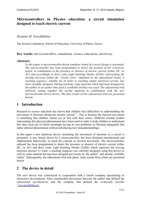
<strong>Microcontrollers</strong> <strong>in</strong> <strong>Physics</strong> <strong>education</strong>: a <strong>circuit</strong> <strong>simulation</strong><br />
designed to teach electric current<br />
Desp<strong>in</strong>a M. Garyfallidou<br />
The Science Laboratory, School of Education, University of Patras, Greece<br />
Key words: microcontrollers, <strong>simulation</strong>, science <strong>education</strong>, electricity.<br />
Abstract:<br />
In this paper a microcontroller-driven emulator board of a novel design is presented.<br />
The microcontroller has been programmed to detect the position of the switch-onboard,<br />
<strong>in</strong> comb<strong>in</strong>ation to the presence or absence of electric current (either DC, or<br />
AC) and accord<strong>in</strong>gly to drive some Light Emitt<strong>in</strong>g Diodes (LEDs) represent<strong>in</strong>g the<br />
mov<strong>in</strong>g electrons with<strong>in</strong> the “<strong>circuit</strong> wires” emulated on the <strong>education</strong>al board. A<br />
teach<strong>in</strong>g sequence, suitable for <strong>in</strong> order to teach<strong>in</strong>g simple electrical <strong>circuit</strong>s, has<br />
been carefully designed. Dur<strong>in</strong>g teach<strong>in</strong>g, some material which had been designed by<br />
the author at an earlier time (and is available on-l<strong>in</strong>e) was used. The <strong>education</strong>al trial<br />
followed, test<strong>in</strong>g together the on-l<strong>in</strong>e material <strong>in</strong> comb<strong>in</strong>ation with the new<br />
microcontroller-driven device. The first results of this <strong>education</strong>al trial are presented<br />
here<strong>in</strong>.<br />
1 Introduction<br />
Research <strong>in</strong> science <strong>education</strong> has shown that children face difficulties <strong>in</strong> understand<strong>in</strong>g the<br />
movement of electrons dur<strong>in</strong>g the electric current 1 , 2 . This is because the electron movement<br />
is someth<strong>in</strong>g that children cannot see or feel with their senses. Different (mental models<br />
represent<strong>in</strong>g this physical phenomenon have been used <strong>in</strong> order to help children to understand<br />
this idea, each one of which seem<strong>in</strong>gly hav<strong>in</strong>g its own problems, to illustrate adequately this<br />
rather abstract phenomenon without <strong>in</strong>troduc<strong>in</strong>g new misunderstand<strong>in</strong>gs.<br />
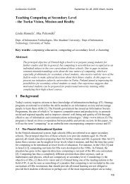
In this paper a new hardware device simulat<strong>in</strong>g the movement of electrons <strong>in</strong> a <strong>circuit</strong> is<br />
presented. A new board, driven by a microcontroller, has been designed manufactured and<br />
implemented didactically, to teach the concept of electron movement. The microcontroller<br />
onboard has been programmed to detect the presence or absence of electric current (either<br />
DC, or AC) and drive some Light Emitt<strong>in</strong>g Diodes (LEDs) which represent the mov<strong>in</strong>g<br />
electrons (picture 1). Later, a teach<strong>in</strong>g sequence was carefully designed, us<strong>in</strong>g this device as<br />
well as some material hav<strong>in</strong>g been designed previously by the author 3 and already available<br />
onl<strong>in</strong>e i . Subsequently, the <strong>education</strong>al trial took place, some results from which are presented<br />
here<strong>in</strong>.<br />
2 The device <strong>in</strong> detail<br />
The new device was constructed <strong>in</strong> cooperation with a Greek company specialis<strong>in</strong>g <strong>in</strong><br />
electronics development. After considerable discussions between the author that def<strong>in</strong>ed the<br />
<strong>education</strong>al specifications and the company that def<strong>in</strong>ed the technically feasible<br />
i www.garyfallidou.org<br />
<strong>ICL</strong> 2010 Proceed<strong>in</strong>gs – Page 410<br />
1(12)
Conference <strong>ICL</strong>2010<br />
September 15 -17, 2010 Hasselt, Belgium<br />
specifications, the shape of the new device was def<strong>in</strong>ed. The most important of user<br />
requirements for the new device was to make a clear and obvious dist<strong>in</strong>ction between the light<br />
bulb and whatever was to be used to represent the free electrons. It was decided to use a<br />
familiar-to-students laboratory type <strong>in</strong>candescence lamp on the <strong>circuit</strong>, while SMD-type<br />
(Surface Mounted Device) LEDs (i.e. very small and flat Light Emitt<strong>in</strong>g Diodes) were used<br />
for the representation of the electrons.<br />
These 32 LEDS have been placed about 1cm apart <strong>in</strong> the surface of a circle and the space<br />
between them (that means the rest of the circle) has been pa<strong>in</strong>ted red. This red l<strong>in</strong>e with the<br />
red LEDs embedded <strong>in</strong> it represents the cables of the <strong>circuit</strong> on the emulator board. The red<br />
colour was chosen on purpose, as it is the same with that of the cables used <strong>in</strong> the stream<strong>in</strong>g<br />
video (presented dur<strong>in</strong>g the lesson) that shows how to construct a simple electrical <strong>circuit</strong><br />
with a light bulb.<br />
The use of this new device <strong>in</strong> class allows students an opportunity to experiment and observe<br />
the phenomena simulated, someth<strong>in</strong>g that could not be performed <strong>in</strong> any other setup <strong>in</strong> any<br />
class or school laboratory 4 , while at the same time allow<strong>in</strong>g some surreal perception as to the<br />
electron movement. Therefore, the new device may be proven to be of high <strong>education</strong>al value.<br />
It is also excit<strong>in</strong>g enough to attract the student’s attention.<br />
It is more beneficial to the students if the use of the device is <strong>in</strong>corporated <strong>in</strong> a teach<strong>in</strong>g<br />
sequence deal<strong>in</strong>g with electric <strong>circuit</strong>s, and electric current. To this purpose, dur<strong>in</strong>g the trial,<br />
already exist<strong>in</strong>g material like the one previously prepared and resid<strong>in</strong>g at<br />
www.garyfallidou.org was used. A teach<strong>in</strong>g sequence us<strong>in</strong>g this onl<strong>in</strong>e material had already<br />
been developed and tested <strong>in</strong> class 3 . It was precisely that previous <strong>education</strong>al trial that<br />
revealed the necessity of a device that allows the visualisation of the electron movement. The<br />
already exist<strong>in</strong>g teach<strong>in</strong>g sequence was, therefore, suitably modified to <strong>in</strong>corporate the new<br />
device.<br />
The device is safe and “easy-to-use” even by very young students and, although it is<br />
microcontroller driven, it does not require any computer knowledge. Nevertheless, when used<br />
<strong>in</strong> classroom, it would be better for the teacher to study carefully the onl<strong>in</strong>e material and<br />
decide which parts he/she wishes to use. The new device is about the size of child’s notebook,<br />
and is lighter than a book (at least lighter than the majority of the books Greek students carry<br />
<strong>in</strong> their bags).<br />
<strong>ICL</strong> 2010 Proceed<strong>in</strong>gs – Page 411<br />
2(12)
Conference <strong>ICL</strong>2010<br />
September 15 -17, 2010 Hasselt, Belgium<br />
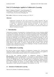
Picture 1.<br />
The new device consists of a microcontroller, 32 LEDs, a light bulb, a switch and an<br />
electricity sensor. An external source (either AC or DC) can be physically connected to this<br />
sensor, both to provide power and to get noticed by the students who handle it (Picture 1). A<br />
microcontroller is a small computer on a s<strong>in</strong>gle <strong>in</strong>tegrated <strong>circuit</strong> (IC - chip) conta<strong>in</strong><strong>in</strong>g a<br />
processor core, memory, and programmable I/O peripherals. Some PROM memory is often<br />
<strong>in</strong>cluded as well as a small amount of RAM. A microcontroller is a k<strong>in</strong>d of m<strong>in</strong>iature<br />
computer. <strong>Microcontrollers</strong> are used <strong>in</strong> many household electronic devices, as they are<br />
designed for embedded special purpose applications, <strong>in</strong> contrast to the microprocessors which<br />
are used for general purpose applications like <strong>in</strong> personal computers.<br />
The specific microcontroller used on the device has been programmed to sense 7 dist<strong>in</strong>ct<br />
cases:<br />
a) The presence of DC current clockwise and the switch <strong>in</strong> the “on” position<br />
b) The presence of DC current counterclockwise and the switch “on”<br />
c) The presence of DC current clockwise and the switch “off”<br />
d) The presence of DC current counterclockwise and the switch “off”<br />
e) The presence of AC current and the switch “on”<br />
f) The presence of AC current and the switch “off”<br />
g) The absence of electric potential (either from an empty battery or no existence of source).<br />
In this case, the position of the switch is <strong>in</strong>different because the <strong>circuit</strong> is open anyway, and<br />
the microcontroller drives the LEDs and the light bulbs accord<strong>in</strong>gly.<br />
If the <strong>circuit</strong> is closed (as <strong>in</strong> the cases a, b, e) the microcontroller flashes the LEDs<br />
successively follow<strong>in</strong>g the direction from the positive pole of the battery to the negative one<br />
and illum<strong>in</strong>ates the light bulb. If the <strong>circuit</strong> is open (case c, d, f and g) the microcontroller<br />
flashes the LEDs randomly (to simulate random motion) and the light bulb does not<br />
illum<strong>in</strong>ate.<br />
<strong>ICL</strong> 2010 Proceed<strong>in</strong>gs – Page 412<br />
3(12)
Conference <strong>ICL</strong>2010<br />
September 15 -17, 2010 Hasselt, Belgium<br />
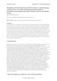
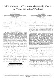
Picture 2.<br />
In picture 2 the back of the device appears. The microcontroller and the battery that provides<br />
energy to the board can be seen. Effort was paid so as this battery to be as <strong>in</strong>dist<strong>in</strong>ct and<br />
obvious to the user as possible.<br />
3 Connect<strong>in</strong>g theory with experimental observation<br />
As already mentioned, a teach<strong>in</strong>g sequence has been specially developed. At the beg<strong>in</strong>n<strong>in</strong>g<br />
students were asked to create a simple <strong>circuit</strong>. For this reason, students worked <strong>in</strong> pairs. Most<br />
of them failed to create a simple <strong>circuit</strong> without the help from the video. After watch<strong>in</strong>g the<br />
stream<strong>in</strong>g video, students were asked to consider what is happen<strong>in</strong>g when a battery is<br />
connected to the <strong>circuit</strong>, which causes the light-bulb to sh<strong>in</strong>e. Then the new device was<br />
presented to the students and the underly<strong>in</strong>g theory was expla<strong>in</strong>ed to them.<br />
At the beg<strong>in</strong>n<strong>in</strong>g the device simulated the absence of battery. Students learn <strong>in</strong> theory that<br />
“when no battery is connected to the <strong>circuit</strong>, the electrons move randomly and the light bulb<br />
does not illum<strong>in</strong>ate”. In the emulator various LEDs are quickly switched on and off at random<br />
order, while the light bulb does not illum<strong>in</strong>ate.<br />
The theory says that: “As soon as a battery is connected to the <strong>circuit</strong> and the <strong>circuit</strong> closes,<br />
which means that all cables are connected properly, and the switch is on, the potential<br />
difference (voltage) applied to the <strong>circuit</strong> from the battery forces the free negatively charged<br />
electrons to move from the po<strong>in</strong>t with the low potential, to the one with high potential – <strong>in</strong><br />
other words from the negative pole of the battery to the positive one. This flow of electrons is<br />
an example of electric current” (Most school books, and especially the ones for primary<br />
school students, say that this flow of electrons is called electric current, but <strong>in</strong> the teach<strong>in</strong>g<br />
sequence the scientifically correct term was used).<br />
In the emulator device, when the battery is connected and the switch is on, the LEDs flash<br />
successively, represent<strong>in</strong>g the movement of the electrons flow<strong>in</strong>g <strong>in</strong> the direction from the<br />
negative pole of the battery to the positive one. If the battery is connected the other way<br />
round, the LEDs will spark successively follow<strong>in</strong>g the opposite direction. The direction of the<br />
electrons does not affect the illum<strong>in</strong>ation of the light bulb, which is therefore sh<strong>in</strong><strong>in</strong>g<br />
regardless of the direction the free electrons are mov<strong>in</strong>g.<br />
<strong>ICL</strong> 2010 Proceed<strong>in</strong>gs – Page 413<br />
4(12)
Conference <strong>ICL</strong>2010<br />
September 15 -17, 2010 Hasselt, Belgium<br />
Children are also taught (<strong>in</strong> theory) that: “Electric current exists only <strong>in</strong> closed <strong>circuit</strong>s.<br />
Therefore, if the switch is off the <strong>circuit</strong> opens, and although a battery is connected to the<br />
<strong>circuit</strong>, there is no forced movement of electrons. Consequently, when the <strong>circuit</strong> opens the<br />
electrons move randomly and slowly (i.e. thermally) and the light bulb does not illum<strong>in</strong>ate”.<br />
In the emulator, <strong>in</strong> case the switch is open, no mater if the battery is connected to the device<br />
or not, the LEDs spark randomly, and the light bulb does not illum<strong>in</strong>ate. Incidentally, due to<br />
the idiomatic use of the everyday language <strong>in</strong> Greece, the phrase “turn on the lights”<br />
translates (literally) to “open the lights”, which is of course very close to “open the <strong>circuit</strong>”,<br />
only to further confuse the students. The opposite phrase is used for turn<strong>in</strong>g the lights off,<br />
thereby mak<strong>in</strong>g the dist<strong>in</strong>ction between “scientific language” used at school, and “everyday<br />
language” used at home, f<strong>in</strong>al! This is precisely what the teacher tries to avoid as it re<strong>in</strong>forces<br />
the widely accepted op<strong>in</strong>ion amongst pupils, namely that science is irrelevant to everyday life.<br />
There is not much that an experienced teacher can do about it, except to learn to live with the<br />
problem and try to clear out any confusion <strong>in</strong> the best possible way.<br />
After all demonstrations have f<strong>in</strong>ished, all students (one pair at a time) experimented with the<br />
new device. They were asked to try all possible switch and battery comb<strong>in</strong>ations and carefully<br />
observe the results.<br />
For the AC case an ord<strong>in</strong>ary transformer that provides the <strong>circuit</strong> with 12V AC is used<br />
Students learn that “<strong>in</strong> A.C. current the move of electrons changes from clockwise to counterclockwise,<br />
and the frequency of the source will determ<strong>in</strong>e how many times per second this<br />
direction of movement changes”. For the purpose of the emulator presented here<strong>in</strong>, when the<br />
<strong>in</strong>put of the board detects high frequency alternat<strong>in</strong>g current, the frequency is reduced (by the<br />
embedded software program) so as the eye can see the change <strong>in</strong> the direction of the flow of<br />
electrons. The directions of the electrons move changes from clockwise to counter clockwise<br />
and the students can see clearly the change <strong>in</strong> the direction of the electron movement.<br />
Although the alternat<strong>in</strong>g current is the type most commonly used everyday, s<strong>in</strong>ce it is the<br />
current that electricity-supply companies provide, it is common practice to postpone the<br />
teach<strong>in</strong>g of it for a while, and to only <strong>in</strong>troduce it after the students had grasped the basic<br />
concepts of electric <strong>circuit</strong>s, and of DC electric current. The alternat<strong>in</strong>g current <strong>simulation</strong><br />
was not taught dur<strong>in</strong>g the trial teach<strong>in</strong>g sequence presented here, although there is a suitable<br />
video available onl<strong>in</strong>e. This was done for several reasons: a) AC current is even more difficult<br />
for the students to understand, because they cannot dist<strong>in</strong>guish the positive and negative pole<br />
and normally the electric current direction changes so quickly from clockwise to counter<br />
clockwise but the light bulb illum<strong>in</strong>ate cont<strong>in</strong>uously. And b) AC current was not taught for<br />
the time be<strong>in</strong>g (worried that this way one might encourage students to “experiment at home”<br />
us<strong>in</strong>g power from an ord<strong>in</strong>ary socket). This is because for this demonstration an ord<strong>in</strong>ary<br />
transformer that lowers the voltage to 12V AC should be used. The students participated <strong>in</strong><br />
the trial were young and not quite aware of the dangers <strong>in</strong>volved when us<strong>in</strong>g the 220-Volt<br />
sockets available at home. They are also unaware of the difference between the current<br />
available <strong>in</strong> the sockets and the one provided by the transformer.<br />
Therefore the teach<strong>in</strong>g of alternat<strong>in</strong>g current was postponed for a later time, <strong>in</strong> order to avoid<br />
students’ misunderstand<strong>in</strong>gs and prevent the acquir<strong>in</strong>g of misconceptions.<br />
4 The <strong>education</strong>al trial<br />
This is the first trial of this new device and, therefore, the knowledge rema<strong>in</strong><strong>in</strong>g to the<br />
students when this new teach<strong>in</strong>g procedure <strong>in</strong>corporat<strong>in</strong>g the new emulator device was<br />
<strong>ICL</strong> 2010 Proceed<strong>in</strong>gs – Page 414<br />
5(12)
Conference <strong>ICL</strong>2010<br />
September 15 -17, 2010 Hasselt, Belgium<br />
f<strong>in</strong>ished, was compared to the knowledge students had before the teach<strong>in</strong>g. A pre-test was<br />
given to the students before the trial, <strong>in</strong> order to identify what they already knew about<br />
electric <strong>circuit</strong>s and the movement of electrons. All the <strong>in</strong>ternationally accepted practices for<br />
perform<strong>in</strong>g research <strong>in</strong> science <strong>education</strong> were followed. The questionnaire was carefully<br />
designed (and was related to the content taught), and effort was paid so as the question to with<br />
clearly stated and specific questions. This is very important <strong>in</strong> order to avoid systematic<br />
errors.<br />
Children form their first ideas about electric current at a very early age, as electric current is<br />
an important part of everyday life. Most of these ideas are not scientifically correct. To avoid<br />
further misconceptions com<strong>in</strong>g from the teacher, it was decided to first test this new device<br />
together with the new e-learn<strong>in</strong>g platform (www.garyfallidou.org) with students of the 4 th<br />
grade of primary school (10 years old), as formal <strong>Physics</strong> teach<strong>in</strong>g starts at the 5 th grade of<br />
primary school. It was decided that, for the <strong>education</strong>al trial it would be more beneficial to the<br />
students to work <strong>in</strong> pairs. This was done <strong>in</strong> order to allow students communicate and<br />
cooperate with each other.<br />
The <strong>education</strong>al trial is still go<strong>in</strong>g on <strong>in</strong> primary schools that have been randomly selected. In<br />
this paper only some prelim<strong>in</strong>ary results from a group of 19 students will be presented. .<br />
A few weeks after the activities, the post-test was given to the students to measure the<br />
rema<strong>in</strong><strong>in</strong>g knowledge. This took an hour, but it was necessary, as it is the only way to<br />
evaluate the success of the new teach<strong>in</strong>g approach with the use of the new device. Data<br />
analysis of the post–tests questions (identical as it happens to those of the pre-test) followed.<br />
The <strong>education</strong>al evaluation of the new teach<strong>in</strong>g approach emerges from the comparison<br />
between the pre and post-tests results.<br />
4.1. Data analysis<br />
All relevant statistics were calculated us<strong>in</strong>g specially constructed software, <strong>in</strong>terfaced with a<br />
popular computational and plott<strong>in</strong>g package. The statistical variance was computed and the<br />
Bessel-corrected standard deviation was calculated for all data po<strong>in</strong>ts to be presented. The<br />
systematic error was set at 2.5%. The total error was then computed by add<strong>in</strong>g <strong>in</strong> quadrature<br />
our systematic with our statistical errors, these two be<strong>in</strong>g <strong>in</strong>dependent, by def<strong>in</strong>ition.<br />
The data are presented <strong>in</strong> double histograms, depict<strong>in</strong>g the percentage of students hold<strong>in</strong>g a<br />
particular idea. The red circles represent the students’ ideas <strong>in</strong> the pre-test while the blue<br />
triangles the students’ ideas after the <strong>education</strong>al trial. The error bars on each po<strong>in</strong>t of the<br />
histogram represent one total standard deviation on either side of the po<strong>in</strong>t, as computed for<br />
this s<strong>in</strong>gle po<strong>in</strong>t. The numerical values of the data are given on the histogram, staggered on<br />
either side of the po<strong>in</strong>ts (for the pre-test red circles they are on the left side, whereas on for the<br />
post-test-blue triangles they are given on the right).<br />
In some of the questions, students were allowed to offer more than one answer. For that<br />
reason, it is possible (for some of the questions presented) the sum of the percentages to addup<br />
to someth<strong>in</strong>g above 100.<br />
<strong>ICL</strong> 2010 Proceed<strong>in</strong>gs – Page 415<br />
6(12)
Conference <strong>ICL</strong>2010<br />
September 15 -17, 2010 Hasselt, Belgium<br />
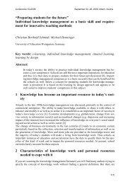
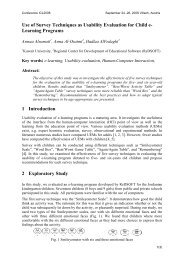
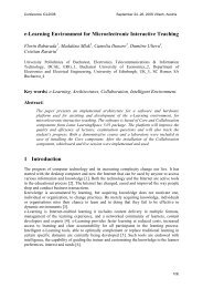
4.2. Question 1: In which of the follow<strong>in</strong>g pictures will the lamp glow?<br />
120<br />
Picture 3.<br />
100<br />
80<br />
84,2<br />
60<br />
40<br />
20<br />
0<br />
0,0<br />
22,2<br />
5,6<br />
0,0 0,0<br />
33,3<br />
10,5<br />
5,6<br />
11,1 11,1<br />
5,3<br />
0,0<br />
5,3<br />
61,1<br />
47,4<br />
11,1<br />
1 2 3 4 5 6 7 8 9<br />
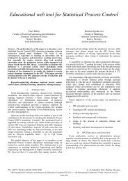
Picture 4.<br />
red circles: the pre-test, blue triangles post test<br />
26,3<br />
There is not one but three of the above pictures where the lamp will glow; therefore the<br />
students answer for each of the pictures <strong>in</strong>dividually as to if the lamp will sh<strong>in</strong>e or not. The<br />
diagram depicts the percentages of the students that considered each picture as correct. On the<br />
post-test there is an improvement on the percentage of the students that answered (4) which is<br />
one of the three correct answers. In the pre-test only 33.3% (±27.5%) of the students<br />
recognizes the correct answer, while <strong>in</strong> the post-test the percentage becomes 84.2% (±26.4%).<br />
In fact this was precisely the <strong>circuit</strong> that the students had built with their own hands dur<strong>in</strong>g the<br />
lesson. It was stressed that <strong>in</strong> order to make a light bulb illum<strong>in</strong>ate it should be connected with<br />
the battery at two po<strong>in</strong>ts a) on the side of the screw and b) under the base. Nevertheless, no<br />
other successful connections rather than the one depicted <strong>in</strong> (4) were presented to the<br />
students, and this seems to <strong>in</strong>dicate with a high level of certa<strong>in</strong>ty that this is the reason they<br />
failed to identify the rest of the connections which would result to the lamp sh<strong>in</strong><strong>in</strong>g. It seems<br />
<strong>ICL</strong> 2010 Proceed<strong>in</strong>gs – Page 416<br />
7(12)
Conference <strong>ICL</strong>2010<br />
September 15 -17, 2010 Hasselt, Belgium<br />
that 9-10 years old children are not able to make the connection l<strong>in</strong>k<strong>in</strong>g theory and real life<br />
situations, as this <strong>in</strong>volves a certa<strong>in</strong> amount of “abstract th<strong>in</strong>k<strong>in</strong>g”. Build<strong>in</strong>g the <strong>circuit</strong> with<br />
their own hands and the visual representations helps students grasp a higher level of<br />
understand<strong>in</strong>g, and therefore to associate the rather abstract diagrammatic picture with reallife<br />
situations. This is <strong>in</strong> excellent agreement previous f<strong>in</strong>d<strong>in</strong>gs by other researchers 5 .<br />
The number of students that chooses picture (8) as correct <strong>in</strong> the post-test is reduced to 47.4<br />
(±27.6%) it was 61.1(± 27.7%) <strong>in</strong> the pre-test, though it seems that this picture confuses the<br />
students. Dur<strong>in</strong>g the teach<strong>in</strong>g, the students created a simple <strong>circuit</strong> us<strong>in</strong>g pla<strong>in</strong> cables, and<br />
then another one us<strong>in</strong>g light bulb holders. They also used light bulb holders <strong>in</strong> order to create<br />
<strong>in</strong> series and <strong>in</strong> parallel connections. Although it was stressed, that <strong>in</strong> a light bulb holder the<br />
one end touches the screw of the lamp and the other the bottom of the lamp and children were<br />
asked to observe this carefully it seems that they did not grasp the idea. Besides the teach<strong>in</strong>g<br />
approach took place with<strong>in</strong> 2 school hours. Therefore the students did not have the chance to<br />
repeat the experiments (us<strong>in</strong>g pla<strong>in</strong> cables with no crocodile clips at the end and no light bulb<br />
holders) and to re-th<strong>in</strong>k what they have done. The last experiments they performed were with<br />
the use of light bulb holders, and therefore it was not very clear for them where the cables<br />
were connected. This perhaps is the reason the students were confused.<br />
Picture (9) also confused the students. Perhaps it is not very clear <strong>in</strong> this picture (9), which<br />
was given to the students only <strong>in</strong> black and white, that one of the cables is not really<br />
connected to the <strong>circuit</strong>.<br />
4.3. Question 2: Which of the follow<strong>in</strong>g pictures to you believe that represent<br />
the electron movement dur<strong>in</strong>g electric current?<br />
1) 2)<br />
4)<br />
3)<br />
5) 6)<br />
7)<br />
Picture 5.<br />
<strong>ICL</strong> 2010 Proceed<strong>in</strong>gs – Page 417<br />
8(12)
Conference <strong>ICL</strong>2010<br />
September 15 -17, 2010 Hasselt, Belgium<br />
90<br />
80<br />
70<br />
60<br />
50<br />
40<br />
30<br />
20<br />
10<br />
0<br />
11,1<br />
31,6<br />
50,0<br />
42,1<br />
0,0<br />
26,3<br />
22,2<br />
15,8<br />
11,1<br />
5,3<br />
27,8<br />
10,5<br />
5,6<br />
1 2 3 4 5 6 7<br />
Picture 6.<br />
red circles: the pre-test , blue triangles post test<br />
0,0<br />
The idea of the movement of electrons is a difficult one for the young students. The electrons<br />
move follow<strong>in</strong>g the direction from the negative pole of the battery to the positive one. While<br />
<strong>in</strong>side the battery, electrons keep mov<strong>in</strong>g from the positive to the negative pole, so as to<br />
complete the <strong>circuit</strong>. To make th<strong>in</strong>gs worse, the so-called “conventional flow” of current is<br />
the opposite one from the electron-flow. The new device represents the electron-flow <strong>in</strong> the<br />
<strong>circuit</strong>, though children had no visual representation of what is happen<strong>in</strong>g <strong>in</strong>side the battery.<br />
S<strong>in</strong>ce the participants of the <strong>education</strong>al trial were 9-10 years old, no reference to the<br />
conventional flow of current was made <strong>in</strong> order to avoid a major misconception.<br />
In the post-test the students’ answers are divided between (a) 31.6% (±27.3%) (b) 42.1%<br />
(±27.6%) and (c) 26.3% (±27.1%). Tak<strong>in</strong>g <strong>in</strong>to account that the <strong>education</strong>al trial lasted 2<br />
hours, the results are encourag<strong>in</strong>g, most children understood that electric current flows<br />
follow<strong>in</strong>g a circle, <strong>in</strong> the whole <strong>circuit</strong>, but it is not as good as we would have liked.<br />
4.4. Question 3: Which of the follow<strong>in</strong>g pictures (referr<strong>in</strong>g to the amount of<br />
electric current <strong>in</strong> the wire) do you consider as correct?<br />
same<br />
same<br />
less<br />
more<br />
1)<br />
2)<br />
<strong>ICL</strong> 2010 Proceed<strong>in</strong>gs – Page 418<br />
9(12)
Conference <strong>ICL</strong>2010<br />
September 15 -17, 2010 Hasselt, Belgium<br />
3)<br />
<strong>in</strong> this part only<br />
4)<br />
<strong>in</strong> this part only<br />
Picture 7.<br />
120<br />
100<br />
80<br />
83,3<br />
60<br />
68,4<br />
40<br />
20<br />
0<br />
11,1<br />
5,6<br />
10,5 10,5 10,5<br />
0,0<br />
1 2 3 4<br />
Picture 8.<br />
red circles: the pre-test, blue triangles post test<br />
We should clarify here that the numbers correspond to the students that consider each<br />
<strong>in</strong>dividual picture as correct. Research <strong>in</strong> science <strong>education</strong> <strong>in</strong>dicates that, before teach<strong>in</strong>g<br />
takes place, most children believe that <strong>in</strong> a <strong>circuit</strong> electric current exists only <strong>in</strong> one of the<br />
cables. This is once more proven correct, <strong>in</strong> that dur<strong>in</strong>g the pre-test 83.3% (±26.6%) of the<br />
students considered picture (4) to be correct.<br />
Dur<strong>in</strong>g the teach<strong>in</strong>g, each group of students connected ammeters before and after the light<br />
bulb and observed the <strong>in</strong>dication. Emphasis was paid to the fact that the <strong>in</strong>dication on both of<br />
them was the same.<br />
It seems that after the teach<strong>in</strong>g, students had a clearer view about the movement of the<br />
electrons and 68.4% (±27.3%) gave the correct answer.<br />
5 Discussion and conclusions<br />
Dur<strong>in</strong>g the teach<strong>in</strong>g approach, children watched a video (from the on-l<strong>in</strong>e material) on the<br />
electronic-whiteboard touch-screen used for show<strong>in</strong>g the video depict<strong>in</strong>g the experiment they<br />
were asked to perform, and subsequently to select whatever equipment they needed to<br />
perform the experiment, from a table where all such the material and apparati was exhibited.<br />
Children faced no difficulties on that. Two <strong>in</strong>terest<strong>in</strong>g observations were made when children<br />
were asked to make more light bulbs illum<strong>in</strong>ate simultaneously: a) most children chose and<br />
<strong>ICL</strong> 2010 Proceed<strong>in</strong>gs – Page 419<br />
10(12)
Conference <strong>ICL</strong>2010<br />
September 15 -17, 2010 Hasselt, Belgium<br />
did succeed to give the <strong>in</strong>-parallel (as opposed to <strong>in</strong>-l<strong>in</strong>e) connection and b) When children<br />
work <strong>in</strong>dividually (as it was done <strong>in</strong> a previous trial of the on-l<strong>in</strong>e material) they collected<br />
from the table with the materials some cables and light bulb holders, but none asked for a<br />
second battery, while when work<strong>in</strong>g <strong>in</strong> pairs, they all collected cables, light bulb holder and<br />
an additional battery. Children <strong>in</strong> Greece are not used to work <strong>in</strong> pairs. Perhaps when they<br />
were asked to make a second light bulb illum<strong>in</strong>ate, they <strong>in</strong>terpreted the task as “the other child<br />
should make his/her own <strong>circuit</strong>”. Consequently, when children worked <strong>in</strong> pairs, the<br />
researcher had to withdraw the extra batteries from their tables and re-pose the question.<br />
Another <strong>in</strong>terest<strong>in</strong>g result is that most of the children faced difficulties when they were asked<br />
to create <strong>in</strong>-series (as opposed to parallel) connections <strong>in</strong> the lab. Students faced difficulties<br />
even after they had seen the relevant video. Many of them faced problems even after a long<br />
analysis on how they should do it.<br />
Time was needed <strong>in</strong> order to expla<strong>in</strong> to the students what the electrons are. Perhaps a new<br />
<strong>education</strong>al device (or a computer-based learn<strong>in</strong>g environment) simulat<strong>in</strong>g the nuclei and the<br />
electrons, and the way they are connected with each other <strong>in</strong> order to create atoms, would be<br />
very helpful.<br />
Although students were unfamiliar with the research method, they expressed no objections to<br />
fil<strong>in</strong>g-<strong>in</strong> the pre-test and the post-test, which is a surpris<strong>in</strong>g result <strong>in</strong> itself. Students asked<br />
details about the device, and they wanted to see the back of it, try<strong>in</strong>g to understand how it<br />
works.<br />
As far as the new device is concerned, children faced no difficulties <strong>in</strong> us<strong>in</strong>g it. Students<br />
responded quite well to the new teach<strong>in</strong>g approach with the use of the new device. They were<br />
truly enthusiastic, and pleased by their experience. They found the new teach<strong>in</strong>g approach and<br />
the use of the new device <strong>in</strong>terest<strong>in</strong>g, and would like to see other scientific topics been taught<br />
us<strong>in</strong>g similar approaches.<br />
Despite the fact that (macroscopically) the present research can only be considered as<br />
prelim<strong>in</strong>ary, it would seem to <strong>in</strong>dicate, nevertheless, that it helps students’ ideas move<br />
towards the scientifically correct ones.<br />
Nevertheless, more research is surely needed us<strong>in</strong>g this new teach<strong>in</strong>g approach aided by the<br />
new device test<strong>in</strong>g students of various ages, and from various geographical areas.<br />
Rererences:<br />
[1] Niedderer H., and Goldberg F., Learn<strong>in</strong>g pathway and knowledge construction <strong>in</strong> electric <strong>circuit</strong>s,<br />
Paper presented at “European Conference on Research <strong>in</strong> Science Education” University of Leeds,<br />
(1995)<br />
[2] Shipstone D., Pupils‘ understand<strong>in</strong>g of simple, electrical <strong>circuit</strong>, <strong>Physics</strong> Education, 23, (1988)<br />
[3] Garyfallidou D. M., “A novel computer based environment designed to teach electric <strong>circuit</strong>s”,<br />
International Conference <strong>ICL</strong> 2009 the challenges of Life Long Learn<strong>in</strong>g, <strong>in</strong> Auer M ed., Kassel<br />
University Press, ISBN 987-3-89958-481-3, total pages 9<br />
[4] Ioannidis G. S. and Garyfallidou D. M., Education us<strong>in</strong>g <strong>in</strong>formation and communication technology<br />
(ICT), and ICT <strong>education</strong>: categories methods and trends, In: Auer M. and Auer U. (Eds.) Proc.<br />
<strong>ICL</strong>2001 workshop: “Interactive Computer aided Learn<strong>in</strong>g, Experiences and visions”, Villach, Austria,<br />
Kassel University Press, (2001) ISBN 3-933146-67-4<br />
<strong>ICL</strong> 2010 Proceed<strong>in</strong>gs – Page 420<br />
11(12)
Conference <strong>ICL</strong>2010<br />
September 15 -17, 2010 Hasselt, Belgium<br />
[5] Tsihouridis Ch. et al. Evaluation of <strong>education</strong>al software regard<strong>in</strong>g its suitability to assist the<br />
laboratory teach<strong>in</strong>g of electrical <strong>circuit</strong>s) <strong>in</strong> Auer M (Ed) International Conference <strong>ICL</strong>2007 ePortfolio<br />
and Quality <strong>in</strong> e-learn<strong>in</strong>g, 2007 Κassel University Press ISBN 978-3-89958-279-6, total pages 15.<br />
Author<br />
Desp<strong>in</strong>a M. Garyfallidou, Ph.D.<br />
University of Patras,<br />
School of Education,<br />
The Science Laboratory,<br />
26500, Rion, Greece<br />
e-mail: d.m.garyfallidou@upatras.gr<br />
d.m.garyfallidou@gmail.com<br />
<strong>ICL</strong> 2010 Proceed<strong>in</strong>gs – Page 421<br />
12(12)