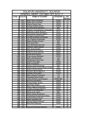
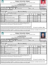
Solapur University Solapur
Solapur University Solapur
Solapur University Solapur

Create successful ePaper yourself
Turn your PDF publications into a flip-book with our unique Google optimized e-Paper software.
<strong>Solapur</strong> <strong>University</strong> <strong>Solapur</strong><br />
Revised Syllabus of B.Sc. II (Electronics)<br />
To be implemented w.e.f.from 2008-09<br />
1) Course Structure: -<br />
Sr.<br />
No. of<br />
Paper<br />
Title<br />
No.<br />
Lectures<br />
Marks<br />
1 III Electronic Circuit Analysis 80 100<br />
2 IV Communication Electronics 80 100<br />
3 Practical 100<br />
2) Nature of Theory Question Paper: -<br />
The nature of theory question paper is same as that for B.Sc. – I<br />
3) Distribution of Practical Marks (100): -<br />
1) Practical from group – A - 21<br />
2) Practical from group – B - 21<br />
3) Practical from group – C - 21<br />
4) Practical from group – D - 21<br />
5) Journal, seminar or industrial Visit 10 + 6 - 16<br />
Break up of 21 marks for each practical<br />
a) Circuit diagram - 4<br />
b) Connection - 4<br />
c) Observations - 4<br />
d) Calculation, graph - 4<br />
e) Results/comments - 2<br />
f) Oral - 3<br />
4) Seminar/ Industrial visit: -<br />
a) Seminars for students may be organized, so as to develop communication<br />
skill, self realization, of concerned topics etc.<br />
OR<br />
b) Industrial visits may be organized to get an awareness on current trends in<br />
electronics Industries.
Paper – III<br />
Electronic Circuit Analysis<br />
Section – I<br />
Electronic Circuit<br />
1) Transistor Amplifier: (12)<br />
1. Transistor Models: Ebbers -Moll Model, Hybrid Model (low<br />
frequency), Hybrid π Model (high frequency).<br />
Basic action of transistor amplifier, D.C. and A.C. analysis of C.B, C.E,<br />
CC Configuration using hybrid model (small signal, low frequency)<br />
,comparison of CB, CE, CC configuration.<br />
FET as CS amplifier (Analysis’s and its Applications),<br />
Multistage Transistor Amplifier: Resistance Coupled, Transformer<br />
Coupled, Direct Couple amplifier, (Graphical analysis of amplifiers).<br />
Darlington pair amplifier.<br />
(Numerical examples)<br />
2) Power Amplifiers: (06)<br />
Class – A, Class – B, Class – AB, Class – C amplifiers, push pull<br />
amplifier, complementary – symmetry amplifier, Distortion in power<br />
amplifiers .<br />
3) Feed back circuits: - (08)<br />
Concept of feed back, General characteristics of feed back, circuits,<br />
effectof negative feed back on distortion, noise, gain, Band Width, Input<br />
impedance, and Output impedance. Concept of Positive Feedback<br />
(Numerical Examples),<br />
4) Oscillators: - (06)<br />
Barkhusian criterion, RC oscillators, Wien bridge oscillator, phases shift<br />
oscillator (Without Mathematical Analysis), LC oscillator – Hartley and<br />
Colpitt’s oscillator, Crystal, its equivalent circuit, crystal oscillator, pierce<br />
crystal oscillator<br />
(Numerical Examples).
5) Differential Amplifier: (08)<br />
Need, Types of Differential Amplifier, Emitter coupled differential<br />
amplifier - operation, characteristics, common mode gain and differential mode<br />
gain, derivation of CMRR. Constant current bias, current mirror bias<br />
(Numerical Examples)<br />
Section – II<br />
(Pulse and Switching circuits)<br />
1) Wave shaping Circuits: - (06)<br />
Need of wave shaping circuit - linear wave shaping circuits<br />
(1) Differentiator (2) Integrator.<br />
Non linear wave shaping - diode clipping & clamping circuits.<br />
2) Time base Circuits: - (08)<br />
General feature of Time base signals, Concept of RC time base circuit,<br />
UJT (construction, working) UJT as a relaxation oscillator, linearity<br />
consideration, constant current charging, miller integrator.<br />
3) Multivibrator using BJT: - (14)<br />
Transistor as a switch, Types of Multivibrator.<br />
Astable Multivibrator: – collector coupled Astable multivibrator - operation,<br />
wave forms, expression of output frequency and duty cycle.<br />
Monostable Multivibrator: - Collector coupled Monostable multivibrator -.<br />
Operation, wave forms, expression of gate width.<br />
Bistable Multivibrator: - Collector coupled Bistable multivibrator, operation,<br />
wave forms.<br />
Schmitt’s Trigger: Operation, Hysterises curve (UTP, LTP), wave forms,<br />
Application<br />
(Numerical Examples)
4) IC’ 555 Timer (08)<br />
Functional Block – diagram of IC 555.<br />
Astable multivibrator – operation, expression for frequency, wave form<br />
Monostable multivibrator – operation, expression of Gate width, wave<br />
forms Application of IC 555 as sequentional Timer.<br />
(Numerical examples)<br />
5) Fourier & Laplace Transform (04)<br />
Definition of Fourier series, formula for evaluation of Fourier coefficients<br />
even and odd functions.<br />
Definition of Fourier Transform, odd and even functions.<br />
Definition of Laplace Transform, Laplace Transform of some<br />
simple functions (Unit step , sine , cosine, exponential function)<br />
Applications to RC and RLC circuit.<br />
Reference books<br />
1) A text book of Applied Electronics by R. S. Sedha. R. S. Chand<br />
Publication.<br />
2) Electronic circuits and devices by Allen mottershed P H I publisher<br />
3) Electronic Devices and Circuits by Boylestead<br />
4) Electronic Devices and circuits by Millman and Halkias<br />
5) Pulse and Switching circuits by Millman and Taub<br />
6) Hand book of Electronics by Sony Gupta.<br />
7) Electronic circuits and systems by N. B. Bapat.<br />
8) Basic Electronics and Linear Circuits by N. N. Bhargaya D. C.<br />
Kulshreshtha & S. C. Gupta T. M. H. Publication.<br />
9) Principal of Electronics by Malvino.<br />
10) Operational Amplifier by Ramakant Gaikwad.<br />
11) Linear Integrated circuit by Roy Chaudhari.<br />
12) A course in Electrical Circuit Analysis by M. L. Sony, J. C. Gupta.<br />
13) Network analysis – M.E. Van Valkenburge ( PHI)
Paper – IV<br />
Communication Electronics<br />
Section – I (Analog Communication)<br />
1) Fundamentals of communication system: - (06)<br />
Need and Importance of communication system. Block Diagram,<br />
Types (Simplex and duplex). Analog, digital communication. Noise in<br />
communication, types of noise (external and internal), Signal to Noise<br />
ratio, Noise figure, Public Address system with block diagram.<br />
(Condenser mic, moving coil speaker & Amplifier system)<br />
Concept of FDM and TDM.<br />
2) Modulation and Demodulation: - (14)<br />
Need of modulation, Types of modulation<br />
Analog modulation: - Amplitude modulation, principle mathematical<br />
expression, modulation index, frequency spectrum, power distribution.<br />
Concept of DSB, SSB & VSB.<br />
Frequency modulation: - Principle, side bands & modulation<br />
index, frequency spectrum. Comparison of AM and FM.<br />
Demodulation: - AM diode detectors (envelop detectors).<br />
FM detector ratio detectors.<br />
Digital modulation: - Concept of ASK, FSK and PCM.<br />
concept of PWM and PPM<br />
3) Antenna and Radio wave propagation: - (06)<br />
Basic principle of Antenna, types of antenna. (half-wave dipole,<br />
Yagi, Dish antenna) Application of antenna.<br />
Radio wave propagation: - Ground wave, sky wave, space wave,<br />
tropospheric line of sight, concept of skip distance (without<br />
mathematical treatment).
4) Radio and TV communications: - (14)<br />
Radio receiver: - Characteristics of receivers, AM superhetrodyne<br />
receiver and FM receiver (block diagram with their explanation)<br />
Television: - Basic concept of Television, scanning and its types<br />
(rectilinear, interlace), picture qualities (brightness, contrast, aspect<br />
ratio, viewing distance, colour level and hue), synchronization.<br />
Colour picture tube (Trinitron).<br />
Composite video signal: bandwidth requirement, VSB transmission<br />
block diagram of monochrome and colour Television receivers with<br />
their explanation.<br />
Section – II<br />
(Digital Communication)<br />
1) Telephone communication system: - (12)<br />
Principle, Telephone handset, subscriber local loop. Need of<br />
exchange, Electronic exchange, Different tones in telephone DTMF<br />
dialing, EPBAX, concept of various value added service<br />
(call transfer, call queing, conference calls, priority call)<br />
2) Modern communication system: - (16)<br />
Fax, Cellular, / Mobile Phone, Picture Phone, Video<br />
conferencing, concept of ISDN.<br />
Computer communication:- Computer Network, Network<br />
topology, classification (LAN, WAN) concept of internet,<br />
modem. (FSK)<br />
Satellite communication – Geo-Stationary satellite, satellite<br />
communication system, earth station, transponder.<br />
3) Optical fiber communication: - (06)<br />
Block diagram of Optical fiber communication, Source, Detector,<br />
fiber optic cables, transmitter, receivers, splices and connector.
4) Signal Processing : - (06)<br />
Basic elements of digital signal processing system, and its advantages.<br />
Classification of signals. Sampling of analog signal, Sampling therom<br />
aliasing and non-aliasing of signals, reconstruction of signal.<br />
Reference Books<br />
1) Principle of communication by Anokh Singh.<br />
2) Communication Electronics by Frenzel MGH Publication.<br />
3) Electronic communication Engineering by Soni Gupta.<br />
4) Electronic communication by Reddy Coolan.<br />
5) Communication Engineering by U. A. Bakshi and AP Godse, Nirali<br />
Prakashan.<br />
6) Television by Dhake.<br />
7) Monochrome and colour TV. By Gulati<br />
8) Antenna & wave propagation by K. D. Prasad.<br />
9) Digital Data communication – Martin PHI Publication.<br />
10) Analog & Digital communication system by Martin S. Roden, SPD<br />
publication.<br />
11) Optical fiber communication by Giegal<br />
12) Mobile communication by schiller.<br />
13) Digital Signal processing by Palan Technova publication
B.Sc. – II<br />
Practical<br />
List of Experiments<br />
Group A<br />
1) CE/CB amplifier (Gain, I/P impedance O/P impedance)<br />
2) FET CS amplifier (Gain, I/P & O/P impedance)<br />
3) Emitter follower (Gain, I/P & O/P impedance)<br />
4) Coupled Amplifier (RC/TC) (frequency response)<br />
5) Power Amplifier (Push-pull /complementary symmetry) (efficiency)<br />
6) Negative feed back amplifier. (frequency response & feed back factor)<br />
7) RC oscillator (Phase shift / Wein bridge) (Design & testing)<br />
8) LC oscillator ( Hartley / Colpitts )(design & testing)<br />
9) Crystal oscillator (Colpitts / Pierce oscillator )<br />
10) Differential amplifier using BJT ( Gain & CMRR)<br />
Group B<br />
1) Clipping / Clamping circuits<br />
2) Differentiator / Integrator using RC network.<br />
3) UJT oscillator, with constant current source.<br />
4) Miller integrator.<br />
5) Design of Astable Multivibrator using BJT<br />
6) Design of Monostable Multivibrator using BJT<br />
7) Bistable Multivibrator using BJT (AC & DC) triggering)<br />
8) Schmitt’s trigger (hysterysis curve & square wave testing)<br />
9) Design of Astable Multivibrator using IC 555.<br />
10) Design of Monostable Multivibrator Integrator using IC 555
Group – C<br />
1) S/N ratio of PA system.( Noise figure).<br />
2) Amplitude modulation and demodulation.<br />
3) Amplitude modulation (modulation index, frequency spectrum) in A. M.<br />
4) Study of balanced modulator using IC (1496/1596)<br />
5) FM modulation and demodulation<br />
6) Tuned R. F. amplifier.<br />
7) Tuned I. F. amplifier.<br />
8) Mixer stage in superheterodyne receiver.<br />
9) Study of Antenna ( To plot polar graph)<br />
10) Study of composite video signal using pattern generator / IC – 7611.<br />
Group – D<br />
1) Internet – I (Creation of ID, sending & receiving email, file attachment)<br />
2) Internet – II (Search engines for given electronic ICS / Projects)<br />
3) Pspice simulation tool to study circuit design (Amplifier / Oscillator) )<br />
4) Pspice simulation too to study circuit design (Mulativibrator / filter)<br />
5) Voice link using fiber – optic cable<br />
6) Pulse width modulation / Plus position modulation.<br />
7) FSK modulation and demodulation (kit) is allowed)<br />
8) Study of DT MF using IC 8870/9170.<br />
9) Tone generator (Bass and Treble circuit)<br />
10) Graphic equalizer circuit.<br />
11) TDM system using kit. / GPS mobile system using kit<br />
(Minimum 32 experiment must be performed out of which at least six from<br />
each group).