SHORT PULSE Nd:YAG LASER CUTTING OF CFRP SHEET
SHORT PULSE Nd:YAG LASER CUTTING OF CFRP SHEET
SHORT PULSE Nd:YAG LASER CUTTING OF CFRP SHEET

Create successful ePaper yourself
Turn your PDF publications into a flip-book with our unique Google optimized e-Paper software.
<strong>SHORT</strong> <strong>PULSE</strong> <strong>Nd</strong>:<strong>YAG</strong> <strong>LASER</strong> <strong>CUTTING</strong> <strong>OF</strong> <strong>CFRP</strong> <strong>SHEET</strong><br />
I. De Iorio 1 , C. Leone 2 , V. Lopresto 2 N. Pagano 2<br />
1 Dept. of Aerospace Engineering - University of Naples, P.le Tecchio 80, 80125 Naples, Italy<br />
2 Dept. of Materials and Production Engineering, University of Naples, P.le Tecchio 80, 80125 Naples, Italy<br />
Introduction<br />
In the last years fibre reinforced plastic have increase<br />
their use in structural application due to their high<br />
specific strength. Although in many application<br />
composites are cured to final shape, cutting and<br />
drilling can still be required. However machining of<br />
<strong>CFRP</strong> composites with conventional cutting methods<br />
produce tool wear, damage such as delamination and<br />
fibre pull out [1-2]. Laser cutting is a possible<br />
alternative that not involve mechanical cutting forces<br />
or tool wear, and allow to obtain complex shape too.<br />
However, laser cutting is based on the thermal<br />
interaction between laser beam and the materials, that<br />
produce heat affected zone (HAZ). During the beammaterial<br />
interaction, the time that elapses before the<br />
vaporisation condition for carbon fibres is larger than<br />
that for the resin, so, a great amount of heat is<br />
absorbed by the matrix thanks to the good<br />
conductivity of the fibres. It results in thermal<br />
degradation of both fibres and matrix, in matrix<br />
burning, in fibres debonded from the matrix and<br />
delamination [3]. It results that the kerf and the HAZ<br />
dimensions depend on the interaction time and then<br />
on the cutting speed [4-5]. The use of pulsed<br />
<strong>Nd</strong>:<strong>YAG</strong> laser in cutting operation of <strong>CFRP</strong> was<br />
investigated in [6]. It was found that, the high beam<br />
intensity and the better focusing behaviour of this<br />
lasers, give a narrow kerf and a smaller HAZ<br />
compared to CO 2 ones, if the right parameter<br />
combinations are adopted. Since the HAZ and the<br />
kerf width depend on the energy release-time<br />
dependence, a strategy to decrease the HAZ and the<br />
kerf width could be the use of high pulse energy<br />
released in very short time, like in the case of short or<br />
ultra-short <strong>Nd</strong>:<strong>YAG</strong> laser pulsed source. For this<br />
laser source, the high peak power released in short<br />
time, rapidly heats the material and directly leads to<br />
the evaporation and/or plasma [7], reducing the heat<br />
absorbed by the matrix and then the kerf dimension<br />
and the HAZ extension.<br />
Aim of the work is to study the features and the<br />
performances of a 100 W short pulse <strong>Nd</strong>:<strong>YAG</strong> laser<br />
in cutting 1 mm <strong>CFRP</strong> laminates.<br />
Experimental<br />
A multimode pulsed lamp pumped <strong>Nd</strong>:<strong>YAG</strong> (Starcut<br />
150 from R<strong>OF</strong>IN), working at the wavelength of<br />
1064 nm, with a maximum average power of 150 W<br />
was used in the experiments. The laser allows the<br />
selection of the pulse duration (D), the pulse<br />
frequency (F) and the lamp voltage (V). Cutting tests<br />
were carried out on a 1 mm in thickness <strong>CFRP</strong> plate<br />
obtained by autoclave cure. The lay-up was: 2<br />
external plies of T400 carbon fibre fabric 193 gr/mm 3<br />
for each side and eight internal unidirectional plies of<br />
T400 carbon fibre 145 g/mm 3 in (45 2 /-45 2 ) s sequence.<br />
The matrix was HMF 934 epoxy resin. During the<br />
tests, pulse durations were selected at the values of 1,<br />
0.5 and 0.25 ms, while different values of mean<br />
power (P m ) were used changing F and V. For each<br />
process condition, different beam speeds were tested<br />
and the maximum cutting speed was determined. The<br />
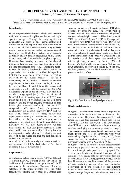
kerf sections of all the samples were examined by<br />
microscopic analysis measuring the top (W t ) and<br />
bottom (W b ) kerf width, the taper angle (T a ) and the<br />
HAZ extension, as reported in figure 1. At the end,<br />
the kerf geometry and the HAZ were related to the<br />
process condition. (W b )<br />
T a<br />
Fig. 1: Kerf section and analysed parameters.<br />
Risults and discussion<br />
W t<br />
W b<br />
HAZ<br />
In figure 2, the maximum cutting speed is reported as<br />
a function of the mean power for the different pulse<br />
duration values. The dashed lines represent the best<br />
fitting ones and they represent a limit between the<br />
“no-cutting” and the “cut region”. The figure reveals<br />
that <strong>CFRP</strong> cutting is possible over a large processing<br />
window enveloping a wide mean power-speed range.<br />
The maximum cutting speed linearly depends on the<br />
mean power and it is in agreement whit what<br />
observed by Caprino et alt. [5] using a CO 2 laser<br />
source. At last, the maximum cutting speed of 11<br />
mm/s was founded with a P m of about 95 W.<br />
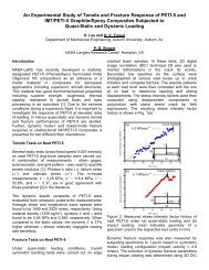
In figure 3, the mean values of fifteen measurements<br />
of the top (open dots) and the bottom (closed dots)<br />
kerf width are plotted against the cutting speed. The<br />
vertical bars denote the standard deviations of ten<br />
samples. From figure, both the kerf widths decrease<br />
at the increase of the cutting speed following a power<br />
law. However, the data distribution and the presence<br />
of data scattering do not allow any particular<br />
observation about the influence of the different<br />
values of pulse duration. Besides, the top kerf width<br />
appears always larger than the declared beam spot
(min. 198, µm against the 170 µm of the declared<br />
beam spot), while the bottom kerf width appears<br />
always lower then the top one, with minimum values,<br />
68 µm, smaller than the beam spot diameters. Using<br />
the data of figure 3, the taper angle was calculated<br />
and plotted against the spot overlap in figure 4. From<br />
the figure, the taper angle is very small, with values<br />
in the range of 1÷6 degree, furthermore the taper<br />
angle tends to increase at the increase of the cutting<br />
speed.<br />
HAZ ( 祄 )<br />
1600<br />
1200<br />
800<br />
400<br />
0<br />
Pulse duration<br />
0.25 ms<br />
0.50 ms<br />
1.00 ms<br />
0 20 40 60 80 100 120<br />
Mean power/Cutting speed (J/mm)<br />
Fig. 2: Influence of the mean power and beam speed<br />
on the cutting regions map.<br />
Kerf width ( 祄 )<br />
500<br />
400<br />
300<br />
200<br />
100<br />
0<br />
Bottom, 0.25 ms Bottom, 0.50 ms Bottom, 1.00 ms<br />
Top, 0.25 ms Top, 0.50 ms Top, 1.00 ms<br />
Bottom kerf<br />
Top kerf<br />
0 2 4 6 8 10 12<br />
Cutting speed (mm/s)<br />
Fig. 3: Bottom kerf width as a function of cutting<br />
speed.<br />
Taper angle (degrees)<br />
8<br />
6<br />
4<br />
2<br />
0<br />
0.25 ms<br />
0.50 ms<br />
1.00 ms<br />
0 2 4 6 8 10 12<br />
Cutting speed (mm/s)<br />
Fig. 4: Taper angle as a function of cutting speed.<br />
The optical microscopy analysis showed the presence<br />
fibres debonding and matrix thermal degradation,<br />
while no delamination was observed. Despite the<br />
limited kerf dimension, a larger HAZ extension<br />
occurs at the centre of the thickness, in<br />
correspondence of unidirectional lamina, as matrix<br />
burning. In figure 5, the HAZ extension was reported<br />
as a function of the cutting speed: the HAZ<br />
extensions depend on the cutting speed by the way of<br />
an exponential law. This can be explained<br />
considering that at the decrease of the cutting speed<br />
the interaction time increases, so more material is<br />
removed or burned, consequently larger and regular<br />
kerf is obtained but, in this case, also HAZ increases.<br />
This effect increases if a long pulse duration is used.<br />
However, there is a singularity for the data obtained<br />
at the minimum duration and the maximum power<br />
(open dots interpolate by the dashed line). In this<br />
condition a linear dependence and a sensible HAZ<br />
extension reduction was observed.<br />
HAZ extension ( 祄 )<br />
1600<br />
1200<br />
800<br />
400<br />
0<br />
Increase of<br />
pulse duration<br />
0.25 ms<br />
0.50 ms<br />
1.00 ms<br />
0 2 4 6 8 10 12<br />
Cutting speed (mm/s)<br />
Fig. 5: HAZ extension as a function of cutting speed.<br />
4. Conclusions<br />
In conclusion it is possible to assert that a 100 W<br />
pulsed <strong>Nd</strong>:<strong>YAG</strong> can be satisfactory used to cut <strong>CFRP</strong><br />
plate 1 mm in thickness, at the maximum cutting<br />
speed of about 11 mm/s. The maximum cutting speed<br />
depends on the released mean power. Narrow kerf<br />
could be obtained increasing the cutting speed up to<br />
its limits. Thermal damages consist of fibres<br />
debonding and matrix degradation while no<br />
delamination was observed. The maximum HAZ<br />
extension occurs at the centre of the laminate in<br />
correspondence of the unidirectional lamina. The<br />
HAZ extension strictly depends on the cutting speed<br />
through an exponential law and it decreases at the<br />
decrease of the pulse duration .<br />
References<br />
1] W. Koenig, C. Wulf, P. Grass, H. Willerchied,<br />
Ann. CIRP, 1985, 34 (2), pp. 537-548.<br />
2] R Komanduri”, Mechanical Engineering, 1993,<br />
Vol. 27, pp. 58-64.<br />
3] V. Tagliaferri, in: N.P. Cheremisinoff (Ed.),<br />
Handbook of Ceramics and Composites, Marcel<br />
Dekker, New York, 1990, pp. 451-467.<br />
4] Mathew, G.L. Goswami, N. Ramakrishnan , N.K.<br />
Naik, J. of Materials Processing Technology,<br />
1999, Vol. 89-90, pp. 198-203.<br />
5] Caprino G., Tagliaferri V., Covelli L., J. Mach<br />
Tools Manufacture, 1995, Vol. 35, (6), pp. 831-<br />
840.<br />
6] W.S. Lau, W.B. Lee, Ann. CIRP 39 (1) (1990)<br />
179–182.<br />
7] Y.L. Yao, H. Chen, W. Zhang, The International J.<br />
of Advanced Manufacturing Technology, 2005,<br />
Vol. 26 (5), pp. 598–608.