

1 Intel 8080 CPU block diagram Internal register addressing: Flag ...
1 Intel 8080 CPU block diagram Internal register addressing: Flag ...
1 Intel 8080 CPU block diagram Internal register addressing: Flag ...

Create successful ePaper yourself
Turn your PDF publications into a flip-book with our unique Google optimized e-Paper software.
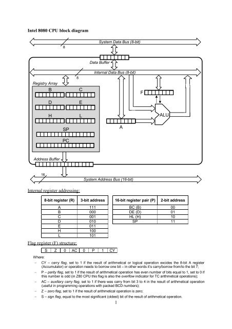
<strong>Intel</strong> <strong>8080</strong> <strong>CPU</strong> <strong>block</strong> <strong>diagram</strong><br />
8<br />
System Data Bus (8-bit)<br />
Data Buffer<br />
Registry Array<br />
B<br />
D<br />
8<br />
C<br />
E<br />
<strong>Internal</strong> Data Bus (8-bit)<br />
F<br />
H<br />
L<br />
ALU<br />
SP<br />
A<br />
PC<br />
Address Buffer<br />
16<br />
System Address Bus (16-bit)<br />
<strong>Internal</strong> <strong>register</strong> <strong>addressing</strong>:<br />
8-bit <strong>register</strong> (R) 3-bit address 16-bit <strong>register</strong> pair (P) 2-bit address<br />
<strong>Flag</strong> <strong>register</strong> (F) structure:<br />
Where:<br />
<br />
<br />
<br />
<br />
<br />
A 111 BC (B) 00<br />
B 000 DE (D) 01<br />
C 001 HL (H) 10<br />
D 010 SP 11<br />
E 011<br />
H 100<br />
L 101<br />
S Z 0 AC 0 P 1 CY<br />
CY – carry flag, set to 1 if the result of arithmetical or logical operation excides the 8-bit A <strong>register</strong><br />
(Accumulator) or operation needs to borrow one bit – in other words it’s carry/borrow from/to the bit 7;<br />
P – parity flag, set to 1 if the result of arithmetical operation has even number of bits equal to 1, set to 0 if<br />
this number is odd (in Z80 <strong>CPU</strong> this flag is also the overflow indicator for TC arithmetical operations);<br />
AC – auxiliary carry flag, set to 1 if there was carry from bit 3 to 4 in the result of arithmetical operation<br />
(useful in programming operations with packed BCD numbers);<br />
Z – zero flag, set to 1 if the result of arithmetical operation is zero;<br />
S – sign flag, equal to the most significant (oldest) bit of the result of arithmetical operation.<br />
1
<strong>Intel</strong> <strong>8080</strong> instruction set architecture<br />
Instruction code formats:<br />
One byte instructions:<br />
i 7 i 6 i 5 i 4 i 3 i 2 i 1 i 0 All bits used to encode instruction, no operands.<br />
i 7 i 6 i 5 i 4 i 3 r r r One operand in 8-bit internal <strong>register</strong> A to L.<br />
i 7 i 6 r r r i 2 i 1 i 0 One operand in 8-bit internal <strong>register</strong> A to L.<br />
i 7 i 6 r1 r1 r1 r2 r2 r2 Two operands in two 8-bit internal <strong>register</strong>s A to L.<br />
i 7 i 6 p p i 3 i 2 i 1 i 0 One operand in 16-bit <strong>register</strong> pair BC, DE, HL or in SP.<br />
Two byte instructions:<br />
i 7 i 6 i 5 i 4 i 3 i 2 i 1 i 0 All bits of the first byte used to encode instruction,<br />
d 7 d 6 d 5 d 4 d 3 d 2 d 1 d 0 the second byte is the immediate operand (argument).<br />
i 7 i 6 r r r i 2 i 1 i 0 First operand in 8-bit internal <strong>register</strong> A to L,<br />
d 7 d 6 d 5 d 4 d 3 d 2 d 1 d 0 the second operand is immediate.<br />
i 7 i 6 i 5 i 4 i 3 i 2 i 1 i 0 All bits of the first byte used to encode instruction,<br />
p 7 p 6 p 5 p 4 p 3 p 2 p 1 p 0 the second byte is the 8-bit address of I/O port.<br />
Three byte instructions with immediate memory <strong>addressing</strong>:<br />
i 7 i 6 p p i 3 i 2 i 1 i 0 First operand in 16-bit <strong>register</strong> pair BC, DE, HL or in SP,<br />
l 7 l 6 l 5 l 4 l 3 l 2 l 1 l 0 the second byte is lower part of 16-bit second operand,<br />
h 7 h 6 h 5 h 4 h 3 h 2 h 1 h 0 the third byte is higher part of the 16-bit second operand.<br />
Three byte instructions with direct memory <strong>addressing</strong>:<br />
i 7 i 6 i 5 i 4 i 3 i 2 i 1 i 0 All bits of the first byte used to encode instruction,<br />
l 7 l 6 l 5 l 4 l 3 l 2 l 1 l 0 the second byte is lower part of 16-bit address in memory,<br />
h 7 h 6 h 5 h 4 h 3 h 2 h 1 h 0 the third byte is higher part of address of the operand.<br />
i 7 i 6 i 5 i 4 i 3 i 2 i 1 i 0 All bits of the first byte used to encode instruction,<br />
l 7 l 6 l 5 l 4 l 3 l 2 l 1 l 0 the second byte is lower part of 16-bit address,<br />
h 7 h 6 h 5 h 4 h 3 h 2 h 1 h 0 the third byte is higher part of address of jump or call.<br />
<strong>Internal</strong> <strong>register</strong>s A, B, C, D, E, H, L (rrr), pairs of <strong>register</strong>s BC, DE, HL and SP <strong>register</strong> (pp)<br />
are addressed according to rules shown on first page.<br />
<strong>Intel</strong>’s processors always store data longer than one byte in the lower-to-higher byte order –<br />
little endian convention.<br />
Mnemonics used for instructions are copyrighted, so other processors which instruction lists<br />
are compatible with <strong>8080</strong> (Z80 for example) have different names and mnemonics for the<br />
same instructions.<br />
2
Instruction list:<br />
Data transfer instructions<br />
MOV R1, R2 (Move <strong>register</strong>)<br />
0 1 r1 r1 r1 r2 r2 r2 R1 R2 data from R2 is copied to R1<br />
MOV R, M (Move from memory, address in HL)<br />
0 1 r r r 1 1 0 R [HL] data from memory (address in HL) copied to R<br />
MOV M, R (Move to memory, address in HL )<br />
0 1 1 1 0 r r r [HL] R data from R copied to memory (address in HL)<br />
MVI R, data8<br />
(Move to <strong>register</strong> immediate)<br />
0 0 r r r 1 1 0 R data8 1 byte (next to instruction) copied to R<br />
d 7 d 6 d 5 d 4 d 3 d 2 d 1 d 0<br />
MVI M, data8 (Move to memory immediate)<br />
0 0 1 1 0 1 1 0 [HL] data8 1 byte copied to memory (address in HL)<br />
d 7 d 6 d 5 d 4 d 3 d 2 d 1 d 0<br />
LXI P, data16 (Load <strong>register</strong> pair immediate)<br />
0 0 p p 0 0 0 1 P data16 2 bytes copied to <strong>register</strong> pair<br />
l 7 l 6 l 5 l 4 l 3 l 2 l 1 l 0 “lower” <strong>register</strong> – 2 nd byte<br />
h 7 h 6 h 5 h 4 h 3 h 2 h 1 h 0 “higher” <strong>register</strong> – 3 rd byte<br />
LDA addr16<br />
(Load accumulator direct)<br />
0 0 1 1 1 0 1 0 A [addr16] 1 byte copied to <strong>register</strong> A from memory<br />
l 7 l 6 l 5 l 4 l 3 l 2 l 1 l 0 lower byte of address – 2 nd byte<br />
h 7 h 6 h 5 h 4 h 3 h 2 h 1 h 0 higher byte of address – 3 rd byte<br />
STA addr16<br />
(Store accumulator direct)<br />
0 0 1 1 0 0 1 0 [addr16] A 1 byte copied to memory from <strong>register</strong> A<br />
l 7 l 6 l 5 l 4 l 3 l 2 l 1 l 0 lower byte of address – 2 nd byte<br />
h 7 h 6 h 5 h 4 h 3 h 2 h 1 h 0 higher byte of address – 3 rd byte<br />
LHLD addr16 (Load H and L direct)<br />
0 0 1 1 0 0 1 0 L [addr16] 2 bytes copied from memory to HL<br />
l 7 l 6 l 5 l 4 l 3 l 2 l 1 l 0 H [addr16 + 1] lower byte of address – 2 nd byte<br />
h 7 h 6 h 5 h 4 h 3 h 2 h 1 h 0 higher byte of address – 3 rd byte<br />
SHLD addr16 (Store H and L direct)<br />
0 0 1 0 0 0 1 0 [addr16] L 2 bytes copied from HL to memory<br />
l 7 l 6 l 5 l 4 l 3 l 2 l 1 l 0 [addr16 + 1] H lower byte of address – 2 nd byte<br />
h 7 h 6 h 5 h 4 h 3 h 2 h 1 h 0 higher byte of address – 3 rd byte<br />
3
LDAX P (Load accumulator indirect, address in BC or DE)<br />
0 0 p p 1 0 1 0 A [P] data from memory (address in P) copied to A<br />
STAX P (Store accumulator indirect, address in BC or DE)<br />
0 0 p p 0 0 1 0 [P] A data from A copied to memory (address in P)<br />
XCHG (Exchange H and L with D and E)<br />
1 1 1 0 1 0 1 1 H D L E data in HL and DE is switched<br />
Arithmetical instructions<br />
ADD R<br />
(Add <strong>register</strong>)<br />
1 0 0 0 0 r r r A A + R data from R is added to data in A<br />
flags affected: Z, S, P, CY, AC<br />
ADD M<br />
(Add memory, address in HL)<br />
1 0 0 0 0 1 1 0 A A + [HL] data from memory is added to A<br />
flags affected: Z, S, P, CY, AC<br />
ADI data8<br />
(Add immediate)<br />
1 1 0 0 0 1 1 0 A A + data8 one byte (next to instruction) added to A<br />
d 7 d 6 d 5 d 4 d 3 d 2 d 1 d 0 flags affected: Z, S, P, CY, AC<br />
ADC R<br />
(Add <strong>register</strong> with carry)<br />
1 0 0 0 1 r r r A A + R + CY data from R and CY flag are added to A<br />
flags affected: Z, S, P, CY, AC<br />
ADC M<br />
(Add memory with carry, address in HL)<br />
1 0 0 0 1 1 1 0 A A + [HL] + CY data from memory and CY added to A<br />
flags affected: Z, S, P, CY, AC<br />
ACI data8<br />
(Add immediate with carry)<br />
1 1 0 0 1 1 1 0 A A + data8 + CY one byte and CY added to A<br />
d 7 d 6 d 5 d 4 d 3 d 2 d 1 d 0 flags affected: Z, S, P, CY, AC<br />
SUB R<br />
(Subtract <strong>register</strong>)<br />
1 0 0 1 0 r r r A A - R data from R is subtracted from A<br />
flags affected: Z, S, P, CY, AC<br />
SUB M<br />
(Subtract memory, address in HL)<br />
1 0 0 1 0 1 1 0 A A - [HL] data from memory is subtracted from A<br />
flags affected: Z, S, P, CY, AC<br />
SUI data8<br />
(Subtract immediate)<br />
1 1 0 1 0 1 1 0 A A - data8 one byte subtracted from A<br />
d 7 d 6 d 5 d 4 d 3 d 2 d 1 d 0 flags affected: Z, S, P, CY, AC<br />
4
SBB R<br />
(Subtract <strong>register</strong> with borrow)<br />
1 0 0 1 1 r r r A A - R - CY R and CY are subtracted from A<br />
flags affected: Z, S, P, CY, AC<br />
SBB M (Subtract memory with borrow)<br />
1 0 0 1 1 1 1 0 A A - [HL] - CY data from memory and CY subtracted<br />
from A, flags affected: Z, S, P, CY, AC<br />
SBI data8 (Subtract immediate with borrow)<br />
1 1 0 1 1 1 1 0 A A - data8 - CY one byte and CY subtracted from A<br />
d 7 d 6 d 5 d 4 d 3 d 2 d 1 d 0 flags affected: Z, S, P, CY, AC<br />
INR R<br />
(Increment <strong>register</strong>)<br />
0 0 r r r 1 0 0 R R + 1 Data in R is incremented by 1<br />
flags affected: Z, S, P, AC<br />
INR M<br />
(Increment memory, address in HL)<br />
0 0 1 1 0 1 0 0 [HL] [HL] + 1 Data in memory is incremented by 1<br />
flags affected: Z, S, P, AC<br />
DCR R<br />
(Decrement <strong>register</strong>)<br />
0 0 r r r 1 0 1 R R - 1 Data in R is decremented by 1<br />
flags affected: Z, S, P, AC<br />
DCR M<br />
(Decrement memory, address in HL)<br />
0 0 1 1 0 1 0 1 [HL] [HL] - 1 Data in memory is decremented by 1<br />
flags affected: Z, S, P, AC<br />
INX P<br />
(Increment <strong>register</strong> pair)<br />
0 0 p p 0 0 1 1 P P + 1 Data in <strong>register</strong> pair P is incremented by 1<br />
flags affected: none<br />
DCX P<br />
(Decrement <strong>register</strong> pair)<br />
0 0 p p 1 0 1 1 P P - 1 Data in <strong>register</strong> pair P is decremented by 1<br />
flags affected: none<br />
DAD P<br />
(Decrement <strong>register</strong> pair)<br />
0 0 p p 1 0 0 1 HL HL + P Data in <strong>register</strong> pair P is added to HL<br />
flags affected: CY (from higher byte)<br />
DAA<br />
(Decimal adjust Accumulator)<br />
0 0 1 0 0 1 1 1 A adjust BCD (A) Data in A is adjusted as packed BCD:<br />
if (a 3 …a 0 ) > 9 or AC=1 then (a 3 …a 0 ) (a 3 …a 0 ) + 6<br />
if (a 7 …a 4 ) > 9 or CY=1 then (a 7 …a 4 ) (a 7 …a 4 ) + 6<br />
explanation: 6 is the 4-bit U2 code of -10<br />
flags affected: Z, S, P, CY, AC<br />
5
Logical instructions<br />
ANA R<br />
(AND with <strong>register</strong>)<br />
1 0 1 0 0 r r r A A R Bits in A logically multiplied with bits from R<br />
flags affected: Z, S, P, CY=0, AC=0<br />
ANA M<br />
(AND with memory – address in HL)<br />
1 0 1 0 0 1 1 0 A A [HL] Bits in A logically multiplied with bits from<br />
memory, flags affected: Z, S, P, CY=0, AC=0<br />
ANI data8<br />
(AND immediate)<br />
1 1 1 0 0 1 1 0 A A data8 Bits in A logically multiplied with bits from<br />
d 7 d 6 d 5 d 4 d 3 d 2 d 1 d 0 2 nd byte of instruction, flags affected: Z, S, P, CY=0, AC=0<br />
XRA R<br />
(XOR with <strong>register</strong>)<br />
1 0 1 0 1 r r r A A R Bits in A logically xor-ed with bits from R<br />
flags affected: Z, S, P, CY=0, AC=0<br />
XRA M<br />
(XOR with memory – address in HL)<br />
1 0 1 0 1 1 1 0 A A [HL] Bits in A logically xor-ed with bits from<br />
memory, flags affected: Z, S, P, CY=0, AC=0<br />
XRI data8<br />
(XOR immediate)<br />
1 1 1 0 1 1 1 0 A A data8 Bits in A logically xor-ed with bits from<br />
d 7 d 6 d 5 d 4 d 3 d 2 d 1 d 0 2 nd byte of instruction, flags affected: Z, S, P, CY=0, AC=0<br />
ORA R<br />
(OR with <strong>register</strong>)<br />
1 0 1 1 0 r r r A A R Bits in A logically added with bits from R<br />
flags affected: Z, S, P, CY=0, AC=0<br />
ORA M<br />
(OR with memory – address in HL)<br />
1 0 1 1 0 1 1 0 A A [HL] Bits in A logically added with bits from<br />
memory, flags affected: Z, S, P, CY=0, AC=0<br />
ORI data8<br />
(OR immediate)<br />
1 1 1 1 0 1 1 0 A A data8 Bits in A logically added with bits from<br />
d 7 d 6 d 5 d 4 d 3 d 2 d 1 d 0 2 nd byte of instruction, flags affected: Z, S, P, CY=0, AC=0<br />
CMP R<br />
(Compare with <strong>register</strong>)<br />
1 0 1 1 1 r r r A - R Data in R is subtracted from data in A, no result<br />
is stored, only flags are affected: Z, S, P, CY, AC<br />
CMP M<br />
(Compare with memory – address in HL)<br />
1 0 1 1 1 1 1 0 A - [HL] Data in memory is subtracted from data in A, no<br />
result is stored, only flags are affected: Z, S, P, CY, AC<br />
6
CPI data8<br />
(Compare immediate)<br />
1 1 1 1 1 1 1 0 A - data8 Data in 2 nd byte of instruction is subtracted<br />
d 7 d 6 d 5 d 4 d 3 d 2 d 1 d 0 from data in A, only flags are affected: Z, S, P, CY, AC<br />
Comment:<br />
Interpretation of “compare” operations is possible by checking Z and CY flags after execution:<br />
if Z=1 then values compared are equal,<br />
else (if Z=0)<br />
if CY=0 then A > compared value,<br />
else (if CY=1) A < compared value.<br />
RLC<br />
(Rotate left / rotate logically left)<br />
0 0 0 0 0 1 1 1 A i+1 A i , A 0 A 7 , CY A 7 Bits in A shifted left,<br />
oldest bit copied to youngest bit and CY,<br />
flags affected: CY<br />
RRC<br />
(Rotate right / rotate logically right)<br />
0 0 0 0 1 1 1 1 A i A i+1 , A 7 A 0 , CY A 0 Bits in A shifted right,<br />
youngest bit copied to oldest bit and CY,<br />
flags affected: CY<br />
RAL<br />
(Rotate left through carry / rotate arithmetically left)<br />
0 0 0 1 0 1 1 1 A i+1 A i , A 0 CY, CY A 7 Bits in A shifted left,<br />
CY copied to youngest bit, oldest bit copied to CY,<br />
flags affected: CY<br />
RAR<br />
(Rotate right through carry / rotate arithmetically right)<br />
0 0 0 1 0 1 1 1 A i A i+1 , A 7 CY, CY A 0 Bits in A shifted right,<br />
CY copied to oldest bit, youngest bit copied to CY,<br />
flags affected: CY<br />
CMA<br />
(Complement Accumulator)<br />
0 0 1 0 1 1 1 1 A A Bitwise negation of A (one’s complement)<br />
flags affected: none<br />
CMC<br />
(Complement carry)<br />
0 0 1 1 1 1 1 1 CY CY Negation (inversion) of CY flag<br />
flags affected: CY<br />
Branch instructions<br />
Comment:<br />
These instructions are passing control to the new address in program (not just to the address of next<br />
instruction). There are two basic types of branches:<br />
<br />
<br />
unconditional – just go to new address,<br />
conditional – check if particular condition (detected by status of one of the flags in F <strong>register</strong>)<br />
occurs and jump if so, continue with next instruction if not.<br />
7
The conditions are encoded (inside the codes of instructions) according to this table:<br />
Condition Mnemonic (CND) Code (ccc)<br />
Not zero (Z = 0) NZ 000<br />
Zero (Z = 1) Z 001<br />
No carry (CY = 0) NC 010<br />
Carry (CY = 1) C 011<br />
Parity odd (P = 0) PO 100<br />
Parity even (P = 1) PE 101<br />
Plus (S = 0) P 110<br />
Minus (S = 1) M 111<br />
JMP addr16<br />
(Jump)<br />
1 1 0 0 0 0 1 1 PC [addr16] Unconditional jump to direct address<br />
l 7 l 6 l 5 l 4 l 3 l 2 l 1 l 0 lower byte of address – 2 nd byte<br />
h 7 h 6 h 5 h 4 h 3 h 2 h 1 h 0 higher byte of address – 3 rd byte<br />
JCND addr16 (Conditional jump)<br />
1 1 c c c 0 1 0 if (CND) then PC [addr16]<br />
l 7 l 6 l 5 l 4 l 3 l 2 l 1 l 0 lower byte of address – 2 nd byte<br />
h 7 h 6 h 5 h 4 h 3 h 2 h 1 h 0 higher byte of address – 3 rd byte<br />
CALL addr16 (Call procedure)<br />
1 1 0 0 1 1 0 1 [SP-1] PC H , [SP-2] PC L , SP SP-2,<br />
l 7 l 6 l 5 l 4 l 3 l 2 l 1 l 0 PC [addr16] lower byte of address – 2 nd byte<br />
h 7 h 6 h 5 h 4 h 3 h 2 h 1 h 0 higher byte of address – 3 rd byte<br />
CCND addr16 (Conditional call)<br />
1 1 c c c 0 1 0 if (CND) then [SP-1] PC H , [SP-2] PC L ,<br />
l 7 l 6 l 5 l 4 l 3 l 2 l 1 l 0 SP SP-2, lower byte of address – 2 nd byte<br />
h 7 h 6 h 5 h 4 h 3 h 2 h 1 h 0 PC [addr16] higher byte of address – 3 rd byte<br />
RET<br />
(Return from procedure)<br />
1 1 0 0 1 0 0 1 PC L , [SP], PC H [SP+1], SP SP+2<br />
RCND<br />
(Conditional return from procedure)<br />
1 1 c c c 0 0 0 if (CND) then PC L , [SP], PC H [SP+1], SP SP+2<br />
RST N (Restart procedure / interrupt routine No. N)<br />
1 1 n n n 1 1 1 [SP-1] PC H , [SP-2] PC L , SP SP-2, PC N 8<br />
PCHL<br />
(Move HL to PC)<br />
1 1 1 0 1 0 0 1 PC H H, PC L L<br />
8
Stack manipulations<br />
PUSH P<br />
(Push <strong>register</strong> pair B, D or H on stack)<br />
1 1 p p 0 1 0 1 [SP-1] P H , [SP-2] P L , SP SP-2<br />
PUSH PSW<br />
(Push Processor Status Word on stack)<br />
1 1 1 1 0 1 0 1 [SP-1] A, [SP-2] F, SP SP-2<br />
POP P<br />
(Pop <strong>register</strong> pair B, D or H from stack)<br />
1 1 p p 0 0 0 1 P L [SP], P H [SP+1], SP SP+2<br />
POP PSW<br />
(Pop Processor Status Word from stack)<br />
1 1 1 1 0 0 0 1 F [SP], A [SP+1], SP SP+2<br />
flags affected: Z, S, P, CY, AC<br />
XTHL<br />
(Exchange stack top with HL)<br />
1 1 1 0 0 0 1 1 L [SP], H [SP+1]<br />
SPHL<br />
(Move HL to SP)<br />
1 1 1 1 1 0 0 1 SP HL<br />
Input / Output instructions<br />
IN adr8<br />
(Input from port)<br />
1 1 0 1 1 0 1 1 A Port[adr8] One byte of data from port stored in A<br />
p 7 p 6 p 5 p 4 p 3 p 2 p 1 p 0 Notice: port address is 8-bit long<br />
OUT adr8<br />
(Output to port)<br />
1 1 0 1 0 0 1 1 Port[adr8] A One byte of data from A stored in port<br />
p 7 p 6 p 5 p 4 p 3 p 2 p 1 p 0 Notice: port address is 8-bit long<br />
Other instructions<br />
EI<br />
(Enable interrupt)<br />
1 1 1 1 1 0 1 1 INT input (hardware interrupt signal) is enabled<br />
DI<br />
(Disable interrupt)<br />
1 1 1 1 0 0 1 1 INT input (hardware interrupt signal) is <strong>block</strong>ed<br />
HLT<br />
(Halt)<br />
0 1 1 1 0 1 1 0 Processor is stopped<br />
NOP (No operation)<br />
0 0 0 0 0 0 0 0 Processor doesn’t perform any operation<br />
9