
You also want an ePaper? Increase the reach of your titles
YUMPU automatically turns print PDFs into web optimized ePapers that Google loves.
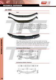
<strong>SLACK</strong> <strong>ADJUSTERS</strong><br />
<strong>MANUAL</strong> <strong>SLACK</strong> <strong>ADJUSTERS</strong><br />
Application Std Part No. ¾ Adj Nut Arm Lengths - A B C D Spline Teeth<br />
Universal Straight Std Trailer KN47001 BR120019 5” 6” 7” 1-½” - 10 Spl<br />
Universal Straight Std ( 4 Hole ) 18048 5” 6” 7” 8” 1-½” - 10 Spl<br />
Universal Truck Drive Straight KN47011 BR120020 5-½” 6-½” 1-½” - 10 Spl<br />
Cranked Low Loader 1296 6” 1-½” - 10 Spl<br />
Left Hand Offset 5/8” KN50060 4” 5” 6” 1-½” - 10 Spl<br />
Right Hand Offset 5/8” KN50070 4” 5” 6” 1-½” - 10 Spl<br />
BPW H, R, KH, KR 4 HOLE 0517452610 150, 180, 220, 250mm 1-½” - 10 Spl<br />
Universal Truck Drive KN44061 BR220219 5-½” 6-½” 1-½” 28 Spl<br />
Universal Straight Std Trailer KN44051 BR210219 5 “ 6” 1-½” 28 Spl<br />
Propar Trailer KN44041 6” 1-⅝” 37 Spl<br />
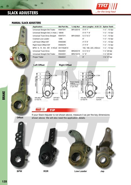
Left Offset<br />
Right Offset<br />
ARM LENGTH<br />
C<br />
B<br />
A<br />
C<br />
½” DIA ½” DIA<br />
B<br />
Proper Viewing<br />
Angle to<br />
Determine left<br />
or right offset<br />
ARM LENGTH<br />
A<br />
BRAKE<br />
SPLINE<br />
& TEETH<br />
OFFSET<br />
<strong>SLACK</strong><br />
SPLINE<br />
& TEETH<br />
STRAIGHT<br />
<strong>SLACK</strong><br />
TIP<br />
Offset<br />
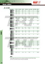
If your Slack Adjuster is not shown above, measure it as per the key dimensions<br />
shown above. We will also need the application details.<br />
BPW ROR Low Loader Jap<br />
128
<strong>SLACK</strong> <strong>ADJUSTERS</strong><br />
AUTO <strong>SLACK</strong> <strong>ADJUSTERS</strong><br />
Auto Slack Adjusters operate exactly the same as Manual Slack Adjusters, without the<br />
need for constant manual adjustment for wear.<br />
There are two styles of actuation-external bracket, and link rod. Through normal brake<br />
operation, the fixed control point moves a rack in the slack adjuster body. As the<br />
clutches are engaged, on regular release, the worm screw is turned by the clutch and<br />
rack. The worm screw then turns the worm wheel adjusting the foundation brakes.<br />
This will continue until lining and drum contact is achieved.<br />
At the time of contact, the clutch to worm shaft is disengaged stopping worm wheel<br />
rotation. (See diagram below)<br />
An Automatic Slack Adjuster should never be adjusted manually while in service. Apart<br />
from the necessary adjustments on installation or at reline, manual adjustment will shorten<br />
clutch life. Check control arms and brackets for damage, these are the most vulnerable<br />
areas of an Auto Slack, and if damaged can cause improper actuation and failure.<br />
External Bracket Actuation<br />
Link Rod Activation<br />
BRAKE<br />
TIP<br />
Not sure what Auto slack you have? The numbers stamped and cast into the body<br />
will help us ID it for you.<br />
129