Installation & Service Manual - Hillphoenix
Installation & Service Manual - Hillphoenix
Installation & Service Manual - Hillphoenix

Create successful ePaper yourself
Turn your PDF publications into a flip-book with our unique Google optimized e-Paper software.
<strong>Installation</strong> & <strong>Service</strong><br />
<strong>Manual</strong><br />
N6F/N6FL<br />
MULTI-SHELF FROZEN FOOD MERCHANDISER<br />
Low Temperature Self Serve Display Cases<br />
This manual has been designed to be used in conjunction with the General<br />
(UL/NSF) <strong>Installation</strong> & <strong>Service</strong> <strong>Manual</strong>.<br />
Save the Instructions in Both <strong>Manual</strong>s for Future Reference!!<br />
This merchandiser conforms to the American National Standard Institute & NSF International Health and Sanitation standard ANSI/NSF 7 - 2003.<br />
PRINTED IN Specifications subject to REPLACES ISSUE PART<br />
IN U.S.A. change without notice. EDITION 1/06 DATE 2/08 NO. 9037160 REV. C<br />
Tyler Refrigeration * Niles, Michigan 49120
N6F/N6FL<br />
CONTENTS<br />
Page<br />
Specifications<br />
N6F/N6FL Specification Sheets . . . . . . . . . . . . . . . . . . . . . . . . . . . . . 4<br />
Pre-installation Responsibilities . . . . . (See General-UL/NSF I&S <strong>Manual</strong>)<br />
<strong>Installation</strong> Procedures<br />
Carpentry Procedures . . . . . . . . . . . . . . . . . . . . . . . . . . . . . . . . . . . 6<br />
Case Pull-Up Locations . . . . . . . . . . . . . . . . . . . . . . . . . . . . . . . . . . 6<br />
Electrical Procedures . . . . . . . . . . . . . . . . . . . . . . . . . . . . . . . . . . . . 6<br />
Electrical Considerations . . . . . . . . . . . . . . . . . . . . . . . . . . . . . . . . . . 6<br />
Case Fan Circuit . . . . . . . . . . . . . . . . . . . . . . . . . . . . . . . . . . . . . . . . . 6<br />
Fluorescent Lamp Circuits . . . . . . . . . . . . . . . . . . . . . . . . . . . . . . . . . 6<br />
Plumbing Procedures . . . . . . . . (See General-UL/NSF I&S <strong>Manual</strong>)<br />
Refrigeration Procedures . . . . . (See General-UL/NSF I&S <strong>Manual</strong>)<br />
Defrost Information . . . . . . . . . . . . . . . . . . . . . . . . . . . . . . . . . . . . . 7<br />
Defrost Control Chart . . . . . . . . . . . . . . . . . . . . . . . . . . . . . . . . . . . . 7<br />
Optional Hot Gas Defrost Operation Requirements . . . . . . . . . . . . . 7<br />
<strong>Installation</strong> Procedure Check Lists (See Gen.-UL/NSF I&S <strong>Manual</strong>)<br />
Wiring Diagrams . . . . . . . . . . . . . . . . . . . . . . . . . . . . . . . . . . . . . . . . . . . . 8<br />
N6F Domestic & Export (50 Hz) Case Circuits . . . . . . . . . . . . . 9<br />
N6FL Domestic & Export (50 Hz) Case Circuits . . . . . . . . . . . . . 13<br />
Cleaning and Sanitation . . . . . . . . . . . . (See General-UL/NSF I&S <strong>Manual</strong>)<br />
Component Removal and <strong>Installation</strong> Instructions for Cleaning 17<br />
Shelves and Shelf Brackets . . . . . . . . . . . . . . . . . . . . . . . . . . . . . . . 17<br />
Bottom Trays . . . . . . . . . . . . . . . . . . . . . . . . . . . . . . . . . . . . . . . . . . 17<br />
Front Air Ducts . . . . . . . . . . . . . . . . . . . . . . . . . . . . . . . . . . . . . . . . 17<br />
Discharge Air Honeycombs . . . . . . . . . . . . . . . . . . . . . . . . . . . . . . . 17<br />
Front Cladding . . . . . . . . . . . . . . . . . . . . . . . . . . . . . . . . . . . . . . . . 17<br />
Page 2 February, 2008
<strong>Installation</strong> & <strong>Service</strong> <strong>Manual</strong><br />
N6F/N6FL<br />
Page<br />
General Information<br />
NSF Product Thermometer . . . . . . . . . . . . . . . . . . . . . . . . . . . . . . . 18<br />
Night Curtains and Strip Doors . . . . . . . . . . . . . . . . . . . . . . . . . . . 18<br />
Case Shelving Information . . . . . . . . . . . . . . . . . . . . . . . . . . . . . . . . 18<br />
<strong>Service</strong> Instructions<br />
Preventive Maintenance . . . . . . (See General-UL/NSF I&S <strong>Manual</strong>)<br />
Ballast and Lighting Locations . . . . . . . . . . . . . . . . . . . . . . . . . . . 19<br />
Fan Locations . . . . . . . . . . . . . . . . . . . . . . . . . . . . . . . . . . . . . . . . 20<br />
Checking Air Velocities . . . . . . . . . . . . . . . . . . . . . . . . . . . . . . . . . 20<br />
Cleaning Honeycomb . . . . . . . . . . . . . . . . . . . . . . . . . . . . . . . . . . . 20<br />
Anti-Sweat Heater Replacement . . . . . . . . . . . . . . . . . . . . . . . . . . 21<br />
Defrost Heater Replacement . . . . . . . . . . . . . . . . . . . . . . . . . . . . . 21<br />
Ambient Air Filter Replacement . . . . . . . . . . . . . . . . . . . . . . . . . . 21<br />
Parts Information<br />
Cladding and Optional Trim Parts List . . . . . . . . . . . . . . . . . . . . . 22<br />
Operational Parts List . . . . . . . . . . . . . . . . . . . . . . . . . . . . . . . . . . 24<br />
TYLER Warranty . . . . . . . . . . . . . . . . . (See General-UL/NSF I&S <strong>Manual</strong>)<br />
The following Low Temperature, Multi-Shelf Frozen Food Merchandiser models are covered<br />
in this manual:<br />
MODEL<br />
N6F<br />
N6FL<br />
DESCRIPTION<br />
6’, 8’ & 12’ MULTI-SHELF FROZEN FOOD MERCHANDISER<br />
6’, 8’ & 12’ MULTI-SHELF FROZEN FOOD MERCHANDISER<br />
WITH 24 1/2” FRONT<br />
January, 2005 Page 3
N6F/N6FL<br />
SPECIFICATIONS<br />
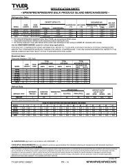
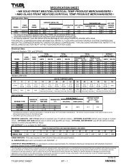
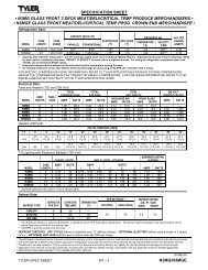
N6F/N6FL Multi-Shelf Frozen Food Merchandiser Specification Sheets<br />
Page 4 March, 2008
<strong>Installation</strong> & <strong>Service</strong> <strong>Manual</strong><br />
N6F/N6FL<br />
March, 2008 Page 5
N6F/N6FL<br />
INSTALLATION PROCEDURES<br />
Carpentry Procedures<br />
Case Pull-Up Locations<br />
All N6F models have four pull-ups at each end<br />
of the case. Pull-ups A, B, C and D are located<br />
as shown and should be installed and tightened<br />
starting with A and finishing with D.<br />
See “General-UL/NSF I&S <strong>Manual</strong>” for<br />
line-up assembly instructions.<br />
Electrical Procedures<br />
Electrical Considerations<br />
CAUTION<br />
Make sure all electrical connections at<br />
components and terminal blocks are tight.<br />
This will prevent burning of electrical<br />
terminals and/or premature component<br />
failure.<br />
NOTE<br />
• Lower raceway cover will be shipped<br />
loose. See the “General-UL/NSF I&S<br />
<strong>Manual</strong>” for raceway cover installation<br />
and removal instructions.<br />
• Since 208V defrost wiring enters the<br />
rear of the case through the outer air<br />
band, the exterior and interior access<br />
holes must be caulked to maintain air<br />
band separation.<br />
Case Fan Circuit<br />
This circuit has three sets of fans (primary,<br />
secondary and ambient) that are supplied by<br />
an uninterrupted, protected 120V circuit. The<br />
case fan circuit is not cycled, except when<br />
equipped for gas defrost. On gas defrost<br />
cases the primary fans are controlled by a<br />
60/30 klixon.<br />
NOTE<br />
With gas defrost, the primary fans will not<br />
restart until the coil temperature reaches<br />
30°F at the fan delay klixon.<br />
Fluorescent Lamp Circuit<br />
The standard case lighting system is T-8<br />
electronic lamps. The N6F standard lighting<br />
is 2-row of horizontal canopy lights and 1-row<br />
of nose lights. The N6FL standard lighting is<br />
3-row of horizontal canopy lights.<br />
Page 6 February, 2008
<strong>Installation</strong> & <strong>Service</strong> <strong>Manual</strong><br />
Defrost Information<br />
See “General-UL/NSF I&S <strong>Manual</strong>” for<br />
operational descriptions for each type of<br />
defrost control.<br />
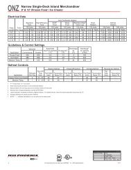
Defrost Control Chart<br />
Defrost<br />
Defrost Defrosts Duration Term.<br />
Type Per Day (Min) Temp.<br />
Electric 2-3 40 55°F<br />
Gas 3-4 22-25 60°F*<br />
*Use 70°F with electronic defrost sensor.<br />
The diagram shows the location for each<br />
defrost type that uses a klixon.<br />
NOTE<br />
• The termination klixon (55/35 Settings) for<br />
electric defrost is located in the right<br />
hand end of the upper electrical raceway.<br />
• The termination klixon for gas defrost is<br />
located next to the rear coil bypass check<br />
valve.<br />
CAUTION<br />
If electronic sensors are used in place of the<br />
klixons, the sensors must be located in the<br />
same location as the klixons for that defrost<br />
type. Any other locations will effect the<br />
refrigeration efficiency of the case.<br />
N6F Optional Hot Gas Defrost Operation<br />
Requirements<br />
When reverse cycle gas defrosting option is<br />
used, it should only be applied to multiple<br />
compressor systems (Parallel racks). A maximum<br />
of not more than 25% of the load on a<br />
January, 2005<br />
N6F/N6FL<br />
given rack should defrost at one time<br />
because the defrosting cases become a<br />
condenser during the defrost period and the<br />
other refrigerated cases must provide enough<br />
heat load to keep a compressor operating.<br />
Do not defrost more than 24 feet of the N6F<br />
at one time to limit the amount of refrigerant<br />
used in that circuit during the defrost.<br />
Insulated partitions must be used between<br />
cases in the same lineup that have<br />
different defrost times.<br />
Defrosts are initiated by a multi-circuit defrost<br />
clock or an electronic defrost controller. At<br />
the beginning of gas defrost the refrigeration<br />
is stopped and the gas is diverted in a<br />
reverse direction through the suction line to<br />
the display case. The refrigeration should be<br />
set to remain off for the complete failsafe time<br />
plus a 5 minute drain off or clear time period.<br />
This type of defrost operation allows the<br />
problem areas in the case to completely clear<br />
without subjecting the refrigerated product to<br />
excessive warm up.<br />
A defrost termination “klixon type” open on<br />
rise thermostat is mounted (on the left hand<br />
side) next to the rear coil check valve that<br />
bypasses defrost refrigerant flow around the<br />
expansion valve. The defrost termination<br />
device along with the mechanical or electronic<br />
defrost control should be set up to cycle or<br />
pulse the hot gas valve during the defrost<br />
time period. If you use a mechanical clock,<br />
you should wire it in parallel with the hot gas<br />
valve. If the return liquid temperature rises to<br />
70°F, the hot gas valve should be closed until<br />
the return liquid temperature cools to 40°F<br />
and then the hot gas valve will reopen and<br />
provide additional heat. This cycling will<br />
continue until the total defrost time has<br />
elapsed. Note that the “klixon type”<br />
thermostat has a time lag associated with it’s<br />
operation so its actual setting is 60°F, but if<br />
an electronic sensor is used for termination,<br />
it should be set at 70°F termination<br />
temperature because it is because it is faster<br />
reacting. Also, if used with an electronic<br />
controller, cycle the hot gas valve when the<br />
lowest sensor temperature (minimum) has<br />
reached 70°F.<br />
Page 7
N6F/N6FL<br />
In addition the primary air band fans on the<br />
N6F are cycled off during the defrost cycle<br />
with a limit “klixon type” thermostat that is<br />
mounted to a coil return bend on the right<br />
hand end of the case. It will cycle the primary<br />
fans off at 60°F and on at 30°F. This helps<br />
minimize the product temperature warmup<br />
during the defrost. All other fans, both<br />
secondary and ambient airband, continue<br />
to run during defrost.<br />
When there is more than one case, the control<br />
wiring must be modified as shown below. This<br />
puts the fourth pole on the special contactor<br />
in a series circuit to the reset solenoid.<br />
FOLLOW THESE INSTRUCTIONS EXACTLY!<br />
Electric Defrost Limit Switch /<br />
Optional Case Temperature Thermostat<br />
WIRING DIAGRAMS<br />
The Defrost Limit Switch and optional Case<br />
Temperature Thermostats are located in the<br />
top raceway with thier sensing bulbs in the<br />
primary air band. The limit switch is factory<br />
preset for 52°F. If defrost is too long, the<br />
hermostat is set too high.<br />
Adjusting the Defrost Limit Switch<br />
ELECTRICIAN NOTE - OVERCURRENT<br />
PROTECTION<br />
120V circuits should be protected by 15 or 20 Amp<br />
devices per the requirements noted on the cabinet<br />
nameplate or the National Electrical Code, Canadian<br />
Electrical Code - Part 1, Section 28. 208V defrost circuits<br />
employ No. 10 AWG field wire leads for field<br />
connections. On remote cases intended for end to<br />
end line-ups, bonding for ground may rely upon the<br />
pull-up bolts.<br />
The following wiring diagrams on pages 9 thru<br />
16 will cover the N6F and N6FL case<br />
circuits with electric defrost and gas defrost.<br />
The canopy lighting circuit is covered in the<br />
case circuit diagrams.<br />
Remove the fiberboard (1) from the end of<br />
the control (2) . Turn the brass adjustment<br />
screw (3) clockwise to raise, or counterclockwise<br />
to lower the termination temperature.<br />
One turn changes temperature setting<br />
approximately 5°F.<br />
Page 8 February, 2008
N6F Domestic & Export (50 Hz) Case Circuits (Electric Defrost)<br />
March, 2008 Page 9
Page 10 March, 2008
N6F Domestic & Export (50 Hz) Case Circuits (Gas Defrost)<br />
March, 2008 Page 11
Page 12 March, 2008
N6FL Domestic & Export (50 Hz) Case Circuits (Electric Defrost)<br />
March, 2008 Page 13
Page 14 March, 2008
N6FL Domestic & Export (50 Hz) Case Circuits (Gas Defrost)<br />
March, 2008 Page 15
Page 16 March, 2008
<strong>Installation</strong> & <strong>Service</strong> <strong>Manual</strong><br />
CLEANING AND SANITATION<br />
Component Removal and<br />
Installa-tion Instructions for<br />
Cleaning<br />
NOTE<br />
See pages G-23 and G-24 in “General-<br />
UL/NSF I&S <strong>Manual</strong>” for important safety<br />
and cleaning instructions.<br />
Shelves and Shelf Brackets<br />
1. Remove product from shelves and store<br />
properly.<br />
2. If shelf has a light, unplug the light cord<br />
from the socket in the rear duct panel.<br />
Completely insert socket cover in the light<br />
socket to protect the receptacle.<br />
3. Push shelves back and then lift up and out<br />
to remove them from the shelf brackets.<br />
4. Remove shelf brackets from slots in rear<br />
uprights.<br />
5. After cleaning, replace in reverse order.<br />
Bottom Trays<br />
1. Remove product from bottom of case.<br />
2. Grasp and lift out each of the bottom trays<br />
from the case interior.<br />
3. After cleaning, replace in reverse order.<br />
Front Air Ducts<br />
1. Remove bottom trays, see this page.<br />
2. Lift out front air duct sections.<br />
3. After cleaning, replace in reverse order.<br />
N6F/N6FL<br />
Discharge Air Honeycomb<br />
1. Outer honeycomb (ambient/secondary),<br />
remove screws and rear retainer plate.<br />
Inner honeycomb (primary), loosen<br />
screws and slide rear retainer plate back<br />
until honeycomb grid sections can be<br />
removed.<br />
NOTE<br />
Note position of the honeycomb grid during<br />
removal so it can be reinstalled the same<br />
way.<br />
2. Remove honeycomb grid sections from<br />
the outer and/or inner top ducts.<br />
CAUTION<br />
Improper installation of the honeycomb grid<br />
section could result in improper air flow<br />
and/or poor refrigeration.<br />
3. After cleaning, replace honeycomb grid<br />
sections as they were removed and secure<br />
with the rear retainer plates and screws.<br />
Lower Cladding<br />
1. Remove kickplate from kickplate supports.<br />
(See General-UL/NSF I&S <strong>Manual</strong>.)<br />
2. Remove mounting screws from top and<br />
bottom of lower cladding and remove<br />
lower cladding.<br />
3. After cleaning, replace lower cladding in<br />
reverse order.<br />
Upper Cladding<br />
1. Remove lower cladding, see above.<br />
2. Remove color band, bumper and bumper<br />
retainer from case. (See General-UL/NSF<br />
I&S <strong>Manual</strong>.)<br />
3. Remove mounting screws from top and<br />
bottom or upper cladding and remove<br />
upper cladding.<br />
4. After cleaning, replace upper cladding and<br />
remaining components in reverse order.<br />
January, 2005 Page 17
N6F/N6FL<br />
GENERAL INFORMATION<br />
NSF Product Thermometer<br />
<strong>Installation</strong><br />
1. Unwrap the thermometer and bracket<br />
assembly shipped loose with the case.<br />
2. Position bracket in front left corner of the<br />
left-most bottom tray. Making sure the<br />
bracket is flush with the left edge, use the<br />
bracket holes as a template for where to<br />
drill the holes.<br />
3. Drill two .196” holes in the bottom tray.<br />
NOTE<br />
For ease of installation, position the<br />
washers and capnuts on the top side of<br />
the bracket and bottom tray.<br />
4. Mount the bracket to the bottom tray with<br />
two screws, washers and capnuts.<br />
Night Curtains and Strip “Doors”<br />
Night curtains and strip “doors” are available<br />
from several souces. They promote energy<br />
savings by partially closing off the front of<br />
the case. TYLER does not promote these<br />
products, but accepts that they are used by<br />
some.<br />
Night curtains are to be pulled down each<br />
night. They considerably cut the refrigeration<br />
load during the night by cycling the compressor<br />
more frequently. If gas or electric defrost<br />
occurs when the curtains are down, a surplus<br />
of moisture laden air will be trapped in the<br />
refrigerated area, and deposit on product.<br />
For this reason, defrosts must be scheduled<br />
to occur when the case is open.<br />
Plastic strip “doors” are permanently hung<br />
over the face of the case. The ambient air<br />
band is disconnected and plugged during<br />
installation. The refrigeration load reduction<br />
alters the system drastically. The compressor<br />
and suction line become oversized and the<br />
need for defrost time and frequency are<br />
reduced. Follow the suppliers recommendations<br />
for best results.<br />
Case Shelving Information<br />
Case Shelving Limitations<br />
Low temperature multi-shelf cases are<br />
particularly sensitive to air pattern changes.<br />
These changes occur if shelves are not<br />
installed or used properly.<br />
Four full rows of shelving must be used in<br />
this case. The bottom row of shelving must<br />
be no more than 24” above the bottom tray.<br />
Shelving can consist of four rows of 22” wide<br />
shelves or three rows of 22” wide shelves and<br />
one bottom row of 18” wide shelves. Do not<br />
use any other shelving combinations.<br />
Page 18 February, 2008
<strong>Installation</strong> & <strong>Service</strong> <strong>Manual</strong><br />
N6F/N6FL<br />
SERVICE INSTRUCTIONS<br />
See “General-UL/NSF I&S <strong>Manual</strong>” for T-8<br />
lamp, canopy ballast, fan blade and motor,<br />
and color band and bumper replacement<br />
instructions.<br />
Ballast and Lighting Locations<br />
Shelf Loading<br />
Observe all the LOAD LINE stickers when<br />
stocking the shelves with product.<br />
• Do not let the product spill over or go<br />
beyond these lines.<br />
• Do not let the product cover up or block<br />
any of the air ducts.<br />
CAUTION<br />
Use of large signage can interfere with the<br />
proper air movement in the case.<br />
Improper air movement will alter the case<br />
temperature and could cause product<br />
loss.<br />
The canopy light ballasts are located under<br />
the canopy on the top of the canopy light<br />
channel. The nose light ballasts are under<br />
the upper front cladding. The canopy light(s)<br />
are under the canopy light channel in the top<br />
of the case. The nose light(s) are behind the<br />
bumper retainer/hand rail.<br />
February, 2008 Page 19
N6F/N6FL<br />
Fan Locations<br />
N6F/N6FL case air velocities should be as<br />
follows:<br />
Fan assemblies are located in three locations<br />
in the N6F and N6FL. The primary fans (1)<br />
are located under the bottom trays and<br />
behind the primary condensing coil. The<br />
secondary fans (2) are located on the top<br />
rear of the case in the secondary air band.<br />
The ambient fans (3) are located on the top<br />
front of the case in the ambient air band.<br />
The ambient fans are under the filters.<br />
Checking Air Velocities<br />
NOTE<br />
• Be sure area above the case is clear!<br />
• Conditioned air must circulate above<br />
the case for the ambient air band intake!<br />
• Do not block top ambient air band filter!<br />
Check air velocities with an Alnor, Jr. Model<br />
8100 Velometer with airscoop modification.<br />
Further information on the Velometer can be<br />
obtained from the TYLER <strong>Service</strong><br />
Department.<br />
Ambient Air -<br />
Secondary Air -<br />
Primary Air -<br />
360 fpm<br />
400 fpm<br />
600 fpm<br />
Cleaning Honeycomb<br />
The inner honeycomb (primary) should not<br />
require cleaning. The outer honeycomb<br />
(ambient/secondary) will require cleaning.<br />
How often will depend on the amount of dust<br />
and lint in the store air.<br />
Need for cleaning can be determined by<br />
comparing clean honeycomb air velocities<br />
with what velocities are being produced<br />
when they are checked. See page 17 in<br />
this manual for cleaning instructions.<br />
Anti-Sweat Heater Replacement<br />
WARNING<br />
Always shut off electricity to the entire<br />
case before replacing an anti-sweat heater.<br />
Electrical power to wire ends could cause<br />
personal injury and/or death.<br />
NOTE<br />
Anti-sweat heater wires will be still be<br />
attached. Tag and cut wires to remove<br />
front molding.<br />
Page 20 February, 2008
<strong>Installation</strong> & <strong>Service</strong> <strong>Manual</strong><br />
N6F/N6FL<br />
1. Remove the screws (1) and front molding<br />
(2) and inner honeycomb (3) from the<br />
interior top of the case.<br />
2. Tag and cut defective anti-sweat wire (4)<br />
and remove aluminum tape and wire from<br />
front molding (2). Discard aluminum<br />
tape.<br />
3. Install new anti-sweat wire (4) in grooves<br />
in front molding (2) and cover with new<br />
aluminum tape.<br />
4. Splice the anti-sweat heater wire (4) to<br />
wire leads from the case.<br />
CAUTION<br />
Make sure wire leads do not get pinched<br />
by the front molding during installation.<br />
Pinched wires could short out the antisweat<br />
heater wire.<br />
1. Remove bottom trays (1) from case (2).<br />
2. Disconnect defective defrost heater (3)<br />
and remove from the defrost heater<br />
support (4) and case (2).<br />
4. Install new defrost heater (3) in reverse<br />
order.<br />
5. Restore electrical power to the case.<br />
Ambient Air Filter Replacement<br />
Ambient air filters are located on top front of<br />
the case above each ambient fan. Replace all<br />
ambient air filters at intial start-up. Routinely<br />
inspect and replace all ambient air filters.<br />
5. Install inner honeycomb (3) and front<br />
molding (2) and secure with screws (1).<br />
6. Restore electrical power to the case.<br />
Defrost Heater Replacement<br />
WARNING<br />
Always shut off electricity to the entire<br />
case before replacing a defrost heater.<br />
Automatic cycling of fans or electrical<br />
power to wire ends could cause personal<br />
injury and/or death.<br />
1. To remove and inspect the air filter, slide<br />
out ambient air filter (1) from air filter<br />
retainer (2). Inspect the ambient air filter.<br />
2. To replace the air filter, slide new ambient<br />
air filter (1) in the air filter retainer (2). Use<br />
10’ X 24” X 1” fiberglass air filters.<br />
NOTE<br />
Do not clean and/or reuse old filters. Poor<br />
ambient air flow will result.<br />
January, 2005 Page 21
N6F/N6FL<br />
PARTS INFORMATION<br />
Cladding and Trim Parts List<br />
Item Description 6’ 8’ 12’<br />
1 Screw (per cover) 5183536 (3) 5183536 (3) 5183536 (3)<br />
2 Pull-Up Angle Cover 5611559 (2) 5611559 (2) 5611559 (2)<br />
3 Screw 5183536 (8) 5183536 (8) 5183536 (8)<br />
4 Canopy Hood Joint Trim, Ptd. 9029422 9029422 9029422<br />
5 Canopy Hood, Ptd. 9025222 9025223 9025224<br />
6 Hand Rail Backer 9025316 9025316 9025316<br />
7 Hand Rail/Bumper Retainer --------------- color per order ---------------<br />
8 Bumper Backer --------------- color per order ---------------<br />
9 Bumper --------------- color per order ---------------<br />
10 Color Band Backer, Ptd. 9040223 9040223 9040223<br />
11 Color Band, Painted 9023795 9023798 9023800<br />
12 Bumper End Trim --------------- color per order ---------------<br />
13 Upr. Fr. Cladding, Ptd. (N6F) 9037331 9037332 9037333<br />
Front Cladding, Ptd. (N6FL) 9037340 9037341 9037342<br />
14 Lwr. Fr. Cladding, Ptd.<br />
(N6F only) 9025644 9025475 9025476<br />
15 Screw 5183536 (4) 5183536(4) 5183536 (6)<br />
16 Raceway Cover Backer --------------- color per order ---------------<br />
17 Raceway Cover End Trim --------------- color per order ---------------<br />
18 Metal Kickplate, Ptd. 9039268 9039269 9039270<br />
Kickplate Joint Trim, Ptd. 9039020 9039020 9039020<br />
Screw, Blk. 9037551 (5) 9037551 (6) 9037551 (6)<br />
19 Shoulder Screw 9025833 (6) 9025833 (8) 9025833 (8)<br />
20 Kickplate Support Assy. 9043402 (3) 9043402 (4) 9043402 (4)<br />
21 Raceway Cover Retainer 9023841 (3) 9023841 (4) 9023841 (5)<br />
Screw 5183536 (9) 5183536 (12) 5183536 (15)<br />
22 Raceway Cover --------------- color per order ---------------<br />
23 Raceway Support 9041326 (4) 9041326 (6) 9041326 (8)<br />
24 Screw 5183536 (8) 5183536 (12) 5183536 (16)<br />
25 LH End Close-off, Painted 9022463 9022463 9022463<br />
RH End Close-off, Painted 9022464 9022464 9022464<br />
26 Raceway 9300242 9300243 9300244<br />
27 Screw, Shoulder 9025833 (12) 9025833 (18) 9025833 (24)<br />
28 Screws 5205439 (4) 5205439 (5) 5205439 (6)<br />
29 Horizontal End Trim 5190028 5190028 5190028<br />
30 Tray Joint Trim 5187950 5187950 5187950<br />
Page 22 February, 2008
<strong>Installation</strong> & <strong>Service</strong> <strong>Manual</strong><br />
N6F/N6FL<br />
Item Description 6’ 8’ 12’<br />
31 Top Shelf Duct Joint 5629694 5629694 5629694<br />
32 Screw 5205439 (4) 5205439 (4) 5205439 (4)<br />
January, 2005 Page 23
N6F/N6FL<br />
Operational Parts List<br />
Case Usage Domestic Export<br />
Electrical Circuit 115 Volt 60 Hertz 220 Volt 50 Hertz<br />
Case Size 6’ 8’ 12’ 8’ 12’<br />
Fan Motors (ambient) 5125532 5125532 5125532 5202538 5202538<br />
5 Watt 5 Watt 5 Watt 5 Watt 5 Watt<br />
(secondary) 5125532 5125532 5125532 5202538 5202538<br />
5 Watt 5 Watt 5 Watt 5 Watt 5 Watt<br />
(primary) 9458944 9458944 9458944 9458942 9458942<br />
23 Watt 23 Watt 23 Watt 18.3 Watt 18.3 Watt<br />
Fan Motor Brackets (ambient) 5120098 5213132 5120098 5120098 5120098<br />
(secondary) 5120098 5120098 5120098 5120098 5120098<br />
(primary) 5205112 5205112 5205112 5205112 5205112<br />
Fan Blades<br />
(amb.)(7.75” 22° 5B) 9040680 ---- ---- ---- 9040680<br />
(amb.)(6” 27° 5B) ---- 9023762 ---- ---- ----<br />
(amb.) (7.75” 20° 5B) ---- ---- 9023760 ---- ----<br />
(amb.)(6” 30° 5B) ---- ---- ---- 9023766 ----<br />
(sec.)(7.75” 15° 5B) 9301932 9301932 9301932 ---- ----<br />
(sec.) (7.75” 22° 5B) ---- ---- ---- 9040680 9040680<br />
(prim.)(8.75” 25° 5B) 5984399 5984399 ---- 5984399 ----<br />
(prim.)(8.75” 30° 5B) ---- ---- 9407319 ---- 9407319<br />
(prim.)(8.75” 18° 5B) ---- ---- ---- 9040682 ----<br />
(prim.)(8.75” 22° 5B) ---- ---- ---- ---- 9040683<br />
Fan Bracket Plate 9041077 9041077 9041077 9041077 9041077<br />
Opt. ECM Fan Motors (ambient) 9025002 9025002 9025002 ---- ----<br />
8 Watt 8 Watt 8 Watt<br />
(secondary) 9025002 9025002 9025002 ---- ----<br />
8 Watt 8 Watt 8 Watt<br />
(primary) 9025003 9025003 9025003 ---- ----<br />
16 Watt 16 Watt 16 Watt<br />
Opt. ECM Fan Motor Brackets<br />
(ambient) 5197471 5205279 5197471 ---- ----<br />
(secondary) 5197471 5197471 5197471 ---- ----<br />
(primary) 5205112 5205112 5205112 ---- ----<br />
Opt. ECM Fan Blades<br />
(amb.)(7.75” 15° 5B) 9301932 ---- ---- ---- ----<br />
(amb.)(6” 15° 5B) ---- 9408191 ---- ---- ----<br />
(amb.)(7.75” 18° 5B) ---- ---- 9023761 ---- ----<br />
Page 24 February, 2008
<strong>Installation</strong> & <strong>Service</strong> <strong>Manual</strong><br />
N6F/N6FL<br />
Case Usage Domestic Export<br />
Case Size 6’ 8’ 12’ 8’ 12’<br />
Opt. ECM Fan Blades (cont.)<br />
(sec.)(7.75” 13° 5B) 9042245 ---- ---- ---- ----<br />
(sec.)(7.75” 15° 5B) ---- 9301932 9301932 ---- ----<br />
(prim.)(8.75” 22° 5B) 9040683 9040683 ---- ---- ----<br />
(prim.)(8.75” 20° 5B) ---- ---- 9023763 ---- ----<br />
Fan Guard (ambient) 5063030 5063030 5063030 5063030 5063030<br />
T-8 Electronic Ballast<br />
(canopy) (N6F) 5966635 5966635 5991030 9322288 9322287<br />
(canopy) (N6FL) 5991030 5991030 5991030 9322287 9322287<br />
(nose) (N6F) 5991029 5991029 5991030 9322286 9322287<br />
T-8 Lampholder 5232279 5232279 5232279 5232279 5232279<br />
Light Switch 5100565 5100565 5100565 5100565 5100565<br />
Electric Defrost Heater (3/case) 9051634 9051633 9051632 5209264 5209265<br />
1350 Watt 1800 Watt 2900 Watt<br />
Special Contactor for Defrost 5109383& 5109383& 5109383& 5109383& 5109383&<br />
w/Aux. Pilot Circuit - 3 Pole 40A 5638229 5638229 5638229 5638229 5638229<br />
Electric Def. Termination T’stat 5058480 5058480 5058480 5058480 5058480<br />
Opt. Case Temperature T’stat 5217892 5217892 5217892 5217892 5217892<br />
Anti-Sweat Heater Wire<br />
(between sec./prim. air bands)5216522 5088067 5088068 5088691 5088692<br />
(in primary air band) 5124216 5124216 5124217 5081147 5081148<br />
NSF Product Thermometer 5967100 5967100 5967100 5967100 5967100<br />
For information on operational parts not listed above contact the TYLER <strong>Service</strong> Parts<br />
Department.<br />
February, 2008 Page 25