3D Sketching Using a 3D Sketch to Create an Oven Rack Frame
3D Sketching Using a 3D Sketch to Create an Oven Rack Frame
3D Sketching Using a 3D Sketch to Create an Oven Rack Frame

Create successful ePaper yourself
Turn your PDF publications into a flip-book with our unique Google optimized e-Paper software.
<strong>3D</strong> <strong><strong>Sketch</strong>ing</strong><br />
file://C:\Documents <strong>an</strong>d Settings\jackyzeng\Local Settings\Temp\~hhA...<br />
Page 1 of 8<br />
2010-10-3<br />
<strong>3D</strong> <strong><strong>Sketch</strong>ing</strong><br />
<strong>Using</strong> SolidWorks, you c<strong>an</strong> create <strong>3D</strong> sketches. You use a <strong>3D</strong> sketch as a sweep path, as a guide<br />
curve for a sweep or loft, as a centerline for a loft, or as one of the key entities in a routing system. A<br />
useful application of <strong>3D</strong> sketching is designing routing systems.<br />
This lesson introduces you <strong>to</strong> <strong>3D</strong> sketching <strong>an</strong>d describes the following concepts:<br />
• <strong><strong>Sketch</strong>ing</strong> relative <strong>to</strong> coordinate systems<br />
• Dimensioning in <strong>3D</strong> space<br />
• Mirroring features<br />
Next<br />
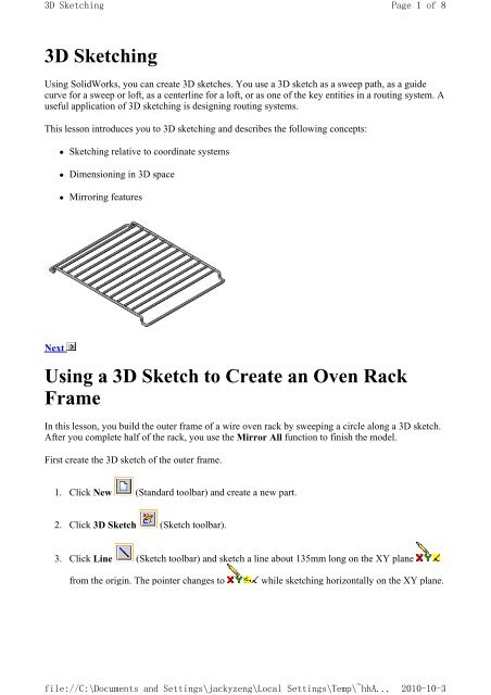
<strong>Using</strong> a <strong>3D</strong> <strong>Sketch</strong> <strong>to</strong> <strong>Create</strong> <strong>an</strong> <strong>Oven</strong> <strong>Rack</strong><br />
<strong>Frame</strong><br />
In this lesson, you build the outer frame of a wire oven rack by sweeping a circle along a <strong>3D</strong> sketch.<br />
After you complete half of the rack, you use the Mirror All function <strong>to</strong> finish the model.<br />
First create the <strong>3D</strong> sketch of the outer frame.<br />
1. Click New (St<strong>an</strong>dard <strong>to</strong>olbar) <strong>an</strong>d create a new part.<br />
2. Click <strong>3D</strong> <strong>Sketch</strong> (<strong>Sketch</strong> <strong>to</strong>olbar).<br />
3. Click Line (<strong>Sketch</strong> <strong>to</strong>olbar) <strong>an</strong>d sketch a line about 135mm long on the XY pl<strong>an</strong>e<br />
from the origin. The pointer ch<strong>an</strong>ges <strong>to</strong><br />
while sketching horizontally on the XY pl<strong>an</strong>e.
<strong>3D</strong> <strong><strong>Sketch</strong>ing</strong><br />
file://C:\Documents <strong>an</strong>d Settings\jackyzeng\Local Settings\Temp\~hhA...<br />
Page 2 of 8<br />
2010-10-3<br />
<strong>Sketch</strong> the line <strong>to</strong> <strong>an</strong> approximate length, then dimension <strong>to</strong> the exact length later.<br />
4. Click Select (St<strong>an</strong>dard <strong>to</strong>olbar), <strong>an</strong>d select the beginning endpoint of the line.<br />
5. In the PropertyM<strong>an</strong>ager, make sure that the endpoint is exactly at the origin (0, 0, 0 as shown<br />
under Parameters), is Coincident with the origin (as shown in Existing Relations) <strong>an</strong>d is<br />
Fully Defined (as shown in Information ).<br />
6. If the endpoint is not at the origin:<br />
• Under Parameters, set X Coordinate, Y Coordinate, <strong>an</strong>d Z Coordinate <strong>to</strong> 0.<br />
• Click Fix in Add Relations.<br />
Next<br />
Now the point is Fully Defined, as shown in Information .<br />
7. Reduce the size of the sketch <strong>to</strong> provide open sketching area on the right side of the graphics<br />
area.<br />
<strong>Using</strong> a <strong>3D</strong> <strong>Sketch</strong> <strong>to</strong> <strong>Create</strong> <strong>an</strong> <strong>Oven</strong> <strong>Rack</strong> <strong>Frame</strong> (Continued)<br />
8. Click Line (<strong>Sketch</strong> <strong>to</strong>olbar) <strong>an</strong>d continue sketching the other lines from the endpoint of<br />
the 135mm line. Each time you begin a new line, the origin for the current coordinate system<br />
is displayed at the beginning of the new line <strong>to</strong> help orient you.<br />
<strong>Sketch</strong> the following lines <strong>to</strong> <strong>an</strong> approximate length, then dimension <strong>to</strong> the exact length<br />
later.<br />
a. <strong>Sketch</strong> down the Y axis for 15.<br />
b. <strong>Sketch</strong> along the X axis for 15.
<strong>3D</strong> <strong><strong>Sketch</strong>ing</strong><br />
file://C:\Documents <strong>an</strong>d Settings\jackyzeng\Local Settings\Temp\~hhA...<br />
Page 3 of 8<br />
2010-10-3<br />
c. Press Tab <strong>to</strong> ch<strong>an</strong>ge the sketch pl<strong>an</strong>e <strong>to</strong> the YZ pl<strong>an</strong>e .<br />
d. <strong>Sketch</strong> along the Z axis for 240.<br />
e. Press Tab twice <strong>to</strong> ch<strong>an</strong>ge the sketch pl<strong>an</strong>e back <strong>to</strong> the XY pl<strong>an</strong>e.<br />
f. <strong>Sketch</strong> back along the X axis for 15.<br />
g. <strong>Sketch</strong> up the Y axis for 15.<br />
h. <strong>Sketch</strong> back along the X axis for 135.<br />
Next<br />
<strong>Using</strong> a <strong>3D</strong> <strong>Sketch</strong> <strong>to</strong> <strong>Create</strong> <strong>an</strong> <strong>Oven</strong> <strong>Rack</strong> <strong>Frame</strong> (Continued)<br />
9. Dimension each of the lines as shown.
<strong>3D</strong> <strong><strong>Sketch</strong>ing</strong><br />
file://C:\Documents <strong>an</strong>d Settings\jackyzeng\Local Settings\Temp\~hhA...<br />
Page 4 of 8<br />
2010-10-3<br />
10. Click <strong>Sketch</strong> Fillet (<strong>Sketch</strong> <strong>to</strong>olbar), <strong>an</strong>d fillet each intersection with a 5mm fillet.<br />
To fillet the intersections, select the point where two lines meet.<br />
11. Click <strong>3D</strong> <strong>Sketch</strong> (<strong>Sketch</strong> <strong>to</strong>olbar) <strong>to</strong> close the sketch.<br />
12. Save the part as rack.sldprt.<br />
Next<br />
<strong>Using</strong> Sweep <strong>to</strong> Complete the Feature<br />
To complete the base feature, sweep a circle along the <strong>3D</strong> sketch path.<br />
1. Select the Right pl<strong>an</strong>e in the FeatureM<strong>an</strong>ager design tree, then click <strong>Sketch</strong> (<strong>Sketch</strong><br />
<strong>to</strong>olbar) <strong>to</strong> open a 2D sketch on that pl<strong>an</strong>e.<br />
2. <strong>Sketch</strong> a circle 5mm diameter circle at the origin.
<strong>3D</strong> <strong><strong>Sketch</strong>ing</strong><br />
file://C:\Documents <strong>an</strong>d Settings\jackyzeng\Local Settings\Temp\~hhA...<br />
Page 5 of 8<br />
2010-10-3<br />
3. Click Exit <strong>Sketch</strong> (<strong>Sketch</strong> <strong>to</strong>olbar).<br />
4. Click Swept Boss/Base (Features <strong>to</strong>olbar).<br />
5. In the PropertyM<strong>an</strong>ager, under Profile <strong>an</strong>d Path:<br />
• Select the circle (<strong>Sketch</strong>1) for Profile .<br />
• Select the <strong>3D</strong> sketch (<strong>3D</strong><strong>Sketch</strong>1) for Path .<br />
6. Click .<br />
Next<br />
Extruding the Supports<br />
<strong>Create</strong> a support by extruding a circular sketch between the frames.<br />
1. Select the Front pl<strong>an</strong>e in the FeatureM<strong>an</strong>ager design tree.<br />
2. Click Extruded Boss/Base (Features <strong>to</strong>olbar).<br />
3. Click Normal To (St<strong>an</strong>dard Views <strong>to</strong>olbar).<br />
4. <strong>Sketch</strong> a circle on what appears <strong>to</strong> be the face of the frame. (The Front pl<strong>an</strong>e is in the center<br />
of the frame wire.) Watch for the inference lines that indicate the centerpoint of the circle is<br />
horizontal <strong>to</strong> the origin.<br />
5. Dimension the center of the circle 11mm from the origin.
<strong>3D</strong> <strong><strong>Sketch</strong>ing</strong><br />
file://C:\Documents <strong>an</strong>d Settings\jackyzeng\Local Settings\Temp\~hhA...<br />
Page 6 of 8<br />
2010-10-3<br />
6. Dimension the diameter of the circle <strong>to</strong> 4<br />
7. Exit the sketch.<br />
8. Click Trimetric (St<strong>an</strong>dard Views <strong>to</strong>olbar).<br />
9. In the PropertyM<strong>an</strong>ager, under Direction 1:<br />
• If necessary, click Reverse Direction so the arrow in the graphics area points in the<br />
correct direction <strong>to</strong> meet the other side.<br />
• Select Up <strong>to</strong> Surface in End condition.<br />
• Select the opposite side of the frame for Face/Pl<strong>an</strong>e .<br />
• If necessary, select Merge result. Merge result controls whether or not you create<br />
separate solid bodies.<br />
10. Click <strong>to</strong> complete the support.<br />
Next<br />
Patterning the Extrusion<br />
Now pattern the extrusion.<br />
1. Click View, Temporary Axes <strong>to</strong> turn on the display of all temporary axes.<br />
The axes must be visible because you need <strong>to</strong> select them <strong>to</strong> create a pattern.
<strong>3D</strong> <strong><strong>Sketch</strong>ing</strong><br />
file://C:\Documents <strong>an</strong>d Settings\jackyzeng\Local Settings\Temp\~hhA...<br />
Page 7 of 8<br />
2010-10-3<br />
2. Select Extrude1 in the FeatureM<strong>an</strong>ager design tree.<br />
3. Click Linear Pattern (Features <strong>to</strong>olbar).<br />
Extrude1 appears in Features <strong>to</strong> Pattern in the PropertyM<strong>an</strong>ager.<br />
4. Click the temporary axis on the face of the frame where you sketched the circle.<br />
The pointer ch<strong>an</strong>ges <strong>to</strong><br />
when you move it over the axis.<br />
In the graphics area, a preview of the pattern appears, <strong>an</strong>d <strong>an</strong> arrow indicating the direction of<br />
the pattern appears on the frame at the right end of the axis. In the Property M<strong>an</strong>ager, Axis<br />
appears in Pattern Direction.<br />
5. Under Direction 1:<br />
• Check the preview of the extrusions <strong>to</strong> make sure they are patterned <strong>to</strong>wards the outer<br />
edge, as shown below. If necessary, click Reverse Direction <strong>to</strong> ch<strong>an</strong>ge the pattern<br />
direction.<br />
• Set Spacing <strong>to</strong> 22.<br />
• Set Number of Inst<strong>an</strong>ces <strong>to</strong> 6.<br />
6. Click .
<strong>3D</strong> <strong><strong>Sketch</strong>ing</strong><br />
file://C:\Documents <strong>an</strong>d Settings\jackyzeng\Local Settings\Temp\~hhA...<br />
Page 8 of 8<br />
2010-10-3<br />
The extrusion pattern is completed.<br />
Next<br />
Mirroring All<br />
Use the Mirror function <strong>to</strong> complete the wire rack.<br />
1. Click View, Temporary Axes <strong>to</strong> hide the temporary axes.<br />
2. Click Mirror (Features <strong>to</strong>olbar).<br />
3. Rotate the half-rack <strong>an</strong>d click on the end face of the frame.<br />
Face appears in Mirror Face/Pl<strong>an</strong>e<br />
in the PropertyM<strong>an</strong>ager.<br />
4. Click Bodies <strong>to</strong> Mirror , then click <strong>an</strong>ywhere on the rack.<br />
5. Click <strong>to</strong> mirror the half rack body about the selected face.<br />
6. Click Isometric (St<strong>an</strong>dard Views <strong>to</strong>olbar).<br />
The rack is completed.<br />
7. Save the part.<br />
Congratulations! You have completed this tu<strong>to</strong>rial!