TL-WA7210N_V2_QIG_7106503999 - TP-Link
TL-WA7210N_V2_QIG_7106503999 - TP-Link
TL-WA7210N_V2_QIG_7106503999 - TP-Link

Create successful ePaper yourself
Turn your PDF publications into a flip-book with our unique Google optimized e-Paper software.
2.4GHz 150Mbps Outdoor Wireless Access Point<br />
<strong>TL</strong>-<strong>WA7210N</strong><br />
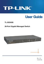
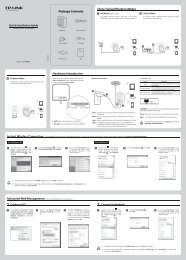
Typical Network<br />
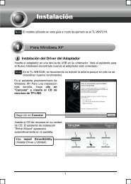
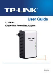
Connecting the Device<br />
1Please use only wired network connection to configure the AP.<br />
Quick Installation Guide<br />
2.4GHz 150Mbps Outdoor Wireless Access Point<br />
<strong>TL</strong>-<strong>WA7210N</strong> is used for remote point-to-point and point-to-multipoint<br />
applications. It makes remote Internet share possible.<br />
AP<br />
Client<br />
Point-to-Point Application<br />
Client 1<br />
1<br />
2<br />
Locate a suitable mounting site for your CPE. To achieve the best performance<br />
of the devices, please select an elevated location where trees, buildings and<br />
large steel structures will not obstruct the antenna signals and which offers<br />
maximum line-of-sight propagation for the devices.<br />
Adjust the direction of your CPE for a best signal. Place the straps through the<br />
slots on the back of the CPE and then around the pole. Tighten the straps.<br />
4<br />
The connection will be similar to the figure below after the above steps are<br />
finished.<br />
CPE<br />
OUTDOOR<br />
Power Cable<br />
INDOOR<br />
Main Electrical Supply<br />
PoE Injector<br />
To Switch or PC<br />
AP Client 2<br />
CAT5 F<strong>TP</strong> Cable Ethernet + DC Power<br />
Client 3<br />
3<br />
Connect one end of an Ethernet cable to the PoE port of the provided PoE and<br />
the other end of the Ethernet cable to the LAN port of the CPE. Then, connect<br />
the LAN port of the PoE to a PC using another Ethernet cable. Finally, plug the<br />
provided power adapter into the DC jack on the PoE, and the other end to a<br />
standard electrical wall socket.<br />
5 Turn on all your network devices and then check to see if the LEDs on the AP<br />
display normally as the diagram below describes.<br />
MODEL NO. <strong>TL</strong>-<strong>WA7210N</strong><br />
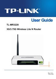
Point-to-Multipoint Application<br />
The typical connection for <strong>TL</strong>-<strong>WA7210N</strong> is shown as above. Please make<br />
sure that the two CPEs are placed face to face, otherwise, the wireless signal<br />
strength might be weak. The figures shown below are a few examples, and<br />
only the first one is correct.<br />
If you are using an external antenna to connect, please refer to Appendix 1.<br />
<strong>TL</strong>-<strong>WA7210N</strong><br />
Power Adapter<br />
PoE<br />
Computer<br />
Solid light<br />
Solid light<br />
Solid light or flashing<br />
If the LEDs display abnormally, please check to see if all the cable<br />
connectors (power adapter and Ethernet cable) are well connected to<br />
your devices.<br />
6 If you use two CPEs to build the network, please make sure that the two CPEs<br />
are placed face to face. Please refer to the Antenna Alignment to get the<br />
optimum signal.<br />
Package Contents<br />
Configuring the Computer<br />
2Assign a static IP address 192.168.0.100 for your computer first before logging in<br />
the management page. Here we take the procedures in Windows 7 for example.<br />
1<br />
Go to Start > Settings > Control<br />
Panel, and then you will see the<br />
following page. Click View<br />
network status and tasks.<br />
4<br />
Double-click Internet Protocol<br />
Version 4 (TCP/IPv4).<br />
31<br />
Configuring the Device<br />
Open your web browser, type in http://192.168.0.254 in the address field<br />
and press Enter<br />
2 A dialog box will prompt you for the User name and Password. Enter the<br />
default values (both are admin) and click OK.<br />
4<br />
Then the page below will appear. Click Next<br />
<strong>TL</strong>-<strong>WA7210N</strong><br />
Passive PoE Injector<br />
<strong>QIG</strong><br />
Power Adapter<br />
2 Click Change adapter settings.<br />
3<br />
Right-click Local Area Connection,<br />
then click Properties.<br />
5<br />
Select Use the following IP<br />
address, enter 192.168.0.100 into<br />
the IP address field and<br />
255.255.255.0 into the Subnet<br />
mask field<br />
1. If the dialog box does not pop up, please refer to T3 in the Appendix 2:<br />
Troubleshooting. Also, T2 will give you some help if you forget the<br />
password.<br />
2. If the device has been restored, the Welcome page will appear, please<br />
read the TERMS OF USE carefully. Then select I agree to these terms of<br />
use and click Login to continue.<br />
3 The web management page will display after your successful login. Click Quick<br />
Setup in the main menu<br />
5 Select the Operation Mode Type according to your needs. Click Next.<br />
Resource CD<br />
Ethernet Cable<br />
6<br />
Click OK to save the configurations<br />
for your computer.<br />
a) If you want to set up a point-to-point connection with <strong>TL</strong>-<strong>WA7210N</strong>, please<br />
skip to Configuration for Point-to-Point Connection. In this part, you will<br />
learn about the configuration for Access Point and Client mode.<br />
b) If you want to set the CPE to the Bridge with AP mode, please skip to<br />
Configuration for Bridge with AP.<br />
<strong>7106503999</strong> REV1.0.0<br />
Mounting Kits<br />
Please reconfigure your computer after successfully configuring the CPE.<br />
Select Obtain an IP address automatically and Obtain DNS server<br />
address automatically in step 5, then click OK.<br />
For configuration for other modes of <strong>TL</strong>-<strong>WA7210N</strong>, please refer to the<br />
User Guide in the resouce CD.<br />
(To be continued...)
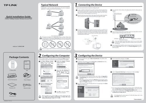
3 Configuring the Device (continued)<br />
Configuration for Point-to-Point Connection<br />
Two devices are needed for this application.<br />
The AP Setting<br />
1<br />
2<br />
Select Access Point for the operation mode, then click Next.<br />
Create an easy-to-remember name for your wireless network. Here we take<br />
<strong>TP</strong>-LINK_211010 for example. Select Most Secure (WPA/WPA2-PSK)<br />
mode and enter a wireless password below to prevent unauthorized access<br />
to your AP. Click Next.<br />
3<br />
The Network Setting page will appear then. It is recommended that you keep the<br />
default settings on this page. Click Next.<br />
The Client Setting<br />
1<br />
2<br />
Select Client for the operation mode, then click Next.<br />
Click Survey button to scan the wireless networks, and choose the SSID<br />
(<strong>TP</strong>-LINK_211010) of the first AP you have configured. Click Next.<br />
3<br />
Change LAN IP Address of the Client from 192.168.0.254 to 192.168.0.X (X can<br />
be any number from 2 to 253) to avoid an IP conflict with the root AP. Here we<br />
take 192.168.0.2 for example. Click Next.<br />
Configuration for Bridge with AP<br />
1<br />
2<br />
Select Bridge with AP for the Operation Mode, then click Next.<br />
Click Survey button to scan the wireless networks, choose the remote AP<br />
that you want to combine with, enter the password of the remote network,<br />
then click Next.<br />
4<br />
Please confirm the configurations you have set, then click Finish/Reboot button to<br />
make all configuraions take effect. If anything is wrong, please go BACK to reset.<br />
5 After successfully logging in, configure the other <strong>TL</strong>-<strong>WA7210N</strong> according to The<br />
Please confirm the configurations you have set, then click Finish/Reboot button<br />
Client Setting.<br />
to make all configuraions take effect. If anything is wrong, please go BACK to reset.<br />
3<br />
Create a name for the Local Wireless Network. The security settings for the local<br />
network will be set the same as the remote AP by default. Click Next.<br />
4<br />
The Network Setting page will appear then. Check the Lan IP Address of the device<br />
to make sure that there’s no IP conflict in the network and click Next to continue.<br />
4<br />
Antenna Alignment<br />
After basic configuration of operation mode, click Wireless > Antenna<br />
Alignment, you can change your CPE’s direction according to the parameters<br />
shown in this page to get a better signal strength.<br />
5<br />
Please confirm the configurations you have set, then click Finish/Reboot button to<br />
make all configuraions take effect. If anything is wrong, please go BACK to reset.<br />
Appendix 1: External Antenna Installation<br />
External Antenna Connection<br />
If you have an external antenna with the RP-SMA(female) port, you could<br />
connect it to the RP-SMA port of your CPE directly.<br />
If you don’t have any external antennas, you are recommended to use <strong>TP</strong>-LINK<br />
products for outdoor solution. You could choose <strong>TL</strong>-ANT2424B (external<br />
antenna), <strong>TL</strong>-ANT24SP (Surge Protector), and <strong>TL</strong>-ANT200PT (Pigtail Cable) to<br />
connect as the following steps:<br />
<strong>TL</strong>-ANT200PT<br />
<strong>TL</strong>-ANT24SP<br />
<strong>TL</strong>-ANT2424B<br />
1 Connect one side of the <strong>TL</strong>-ANT24SP to the RP-SMA port of your CPE<br />
through the <strong>TL</strong>-ANT200PT.<br />
2 Connect the other side of the <strong>TL</strong>-ANT24SP to the <strong>TL</strong>-ANT2424B.<br />
Configure the External Antenna<br />
You will need to assign your computer a Static IP address within the same<br />
range as the AP’s IP address. See the Appendix 2: Troubleshooting - T3 if you<br />
need assistance.<br />
1 Open your web browser, type in http://192.168.0.254 in the address field and<br />
press Enter<br />
2 A dialog box will prompt you for the User name and Password. Enter the default<br />
values (both are admin) and click OK.<br />
3 Configure the External Antenna. Click Wireless >Wireless Advanced, select<br />
External Antenna, then click Save.<br />
Appendix 2: Troubleshooting<br />
T1. How do I restore my AP’s configuration to its factory default settings?<br />
With the AP powered on, press and hold the RESET button for about 8 seconds before<br />
releasing it.<br />
Once the AP is reset, the current configuration settings will be lost and you<br />
will need to reconfigure the router.<br />
GND RESET LAN<br />
T2. What can I do if I forget my password?<br />
1) Restore the AP’s configuration to its factory default settings. If you don’t know how<br />
to do that, please refer to previous section T1;<br />
2) Use the default user name and password: admin, admin;<br />
3) Try to reconfigure your AP by following the instructions of this <strong>QIG</strong>.<br />
T3. What can I do if I cannot access the web-based configuration page?<br />
Restore the AP’s configuration to its factory default settings according to previous<br />
section T1, then assign a static IP address 192.168.0.100 for your computer following<br />
the steps below or referring to 2 Configuring the Computer.<br />
For Windows 7 OS<br />
Go to Start > Settings > Control Panel. Click View network status and tasks ><br />
Change adapter settings, right-click Local Area Connection, select Properties and<br />
then double-click Internet Protocol Version 4 (TCP/IPv4). Select Use the following<br />
IP address, enter 192.168.1.100 into the IP address field, 255.255.255.0 into the<br />
Subnet mask field, select Use the following DNS server addresses, enter the DNS<br />
server address provided by your ISP or network administrator. Click OK.<br />
For Windows XP OS<br />
Go to Start > Control Panel. Click Network and Internet Connections > Network<br />
Connections, right-click Local Area Connection, select Properties and then<br />
double-click Internet Protocol (TCP/IP). Select Use the following IP address, enter<br />
192.168.1.100 into the IP address field, 255.255.255.0 into the Subnet mask field,<br />
select Use the following DNS server addresses, enter the DNS server address<br />
provided by your ISP or network administrator. Click OK.<br />
Tel: +44 (0) 845 147 0017<br />
E-mail: support.uk@tp-link.com<br />
Service time: 24hrs, 7 days a week<br />
Ukraine<br />
Tel: 0800 505 508<br />
E-mail: support.ua@tp-link.com<br />
Service time: Monday to Friday<br />
10:00 to 22:00<br />
Brazil<br />
Toll Free: 0800 608 9799<br />
(Portuguese Service)<br />
E-mail: suporte.br@tp-link.com<br />
Service time: Monday to Friday, 09:00<br />
to 20:00; Saturday, 09:00 to 15:00<br />
Italy<br />
Tel: +39 023 051 9020<br />
E-mail: support.it@tp-link.com<br />
Service time: Monday to Friday<br />
09:00 to 13:00; 14:00 to 18:00<br />
Indonesia<br />
Tel: (+62) 021 6386 1936<br />
E-mail: support.id@tp-link.com<br />
Service time: Monday to Friday<br />
09:00 to 18:00<br />
*Except public holidays<br />
Germany / Austria<br />
Technical Support<br />
For more troubleshooting help, go to www.tp-link.com/en/support/faq<br />
To download the latest Firmware, Driver, Utility and User Guide, go to<br />
http://www.tp-link.com/en/support/download/<br />
For all other technical support, please contact us by using the following details:<br />
Global<br />
Australia / New Zealand<br />
Tel: +86 755 2650 4400<br />
Tel: AU 1300 87 5465<br />
E-mail: support@tp-link.com<br />
NZ 0800 87 5465<br />
Service time: 24hrs, 7 days a week<br />
E-mail: support.au@tp-link.com (Australia)<br />
Singapore<br />
support.nz@tp-link.com (New Zealand)<br />
Tel: +65 6284 0493<br />
Service time: 24hrs, 7 days a week<br />
E-mail: support.sg@tp-link.com<br />
Turkey<br />
Service time: 24hrs, 7 days a week<br />
UK<br />
Tel: +49 1805 875 465 (German Service)<br />
+49 1805 <strong>TP</strong>LINK<br />
+43 820 820 360<br />
E-mail: support.de@tp-link.com<br />
Fee: 0.14 EUR/min from the German fixed<br />
phone network and up to 0.42 EUR/min<br />
from mobile phone<br />
Service time: Monday to Friday, 09:00 to<br />
12:30 and 13:30 to 17:30. GMT+1 or<br />
GMT+2 (Daylight Saving Time in Germany)<br />
*Except bank holidays in Hesse<br />
<strong>TP</strong>-LINK TECHNOLOGIES CO., LTD.<br />
Tel: 0850 7244 488 (Turkish Service)<br />
E-mail: support.tr@tp-link.com<br />
Service time: 09:00 to 21:00<br />
7 days a week<br />
USA / Canada<br />
Toll Free: +1 866 225 8139<br />
E-mail: support.usa@tp-link.com<br />
Service time: 24hrs, 7 days a week<br />
Malaysia<br />
Tel: 1300 88 875 465<br />
Email: support.my@tp-link.com<br />
Service time: 24hrs, 7 days a week<br />
Poland<br />
Tel: +48 (0) 801 080 618 / +48 227 217 563 (if<br />
calls from mobile phone)<br />
E-mail: support.pl@tp-link.com<br />
Service time: Monday to Friday, 09:00 to 17:00.<br />
GMT+1 or GMT+2 (Daylight Saving Time)<br />
Switzerland<br />
Tel: +41 (0) 848 800 998 (German Service)<br />
E-mail: support.ch@tp-link.com<br />
Fee: 4-8 Rp/min, depending on rate of<br />
different time<br />
Service time: Monday to Friday, 09:00 to 12:30<br />
and 13:30 to 17:30. GMT+1 or GMT+2<br />
(Daylight Saving Time)<br />
France<br />
Tel: +33 (0) 820 800 860 (French service)<br />
Email: support.fr@tp-link.com<br />
Fee: 0.118 EUR/min from France<br />
Service time: Monday to Friday, 09:00 to<br />
18:00 *Except French Bank holidays<br />
Russian Federation<br />
Tel: 8 (499) 754 5560<br />
8 (800) 250 5560 (toll-free call from any RF<br />
region)<br />
E-mail: support.ru@tp-link.com<br />
Service time: From 10:00 to 18:00 (Moscow<br />
time) *Except weekends and holidays in<br />
Russian Federation<br />
www.tp-link.com