Worked Solutions Chapter 7 Materials and their use in ... - PEGSnet
Worked Solutions Chapter 7 Materials and their use in ... - PEGSnet
Worked Solutions Chapter 7 Materials and their use in ... - PEGSnet

You also want an ePaper? Increase the reach of your titles
YUMPU automatically turns print PDFs into web optimized ePapers that Google loves.
<strong>Worked</strong> <strong>Solutions</strong><br />
<strong>Chapter</strong> 7 <strong>Materials</strong> <strong>and</strong> <strong>their</strong> <strong>use</strong> <strong>in</strong> structures<br />
7.1 External forces act<strong>in</strong>g on materials<br />
1 B; the cable is be<strong>in</strong>g stretched <strong>and</strong> is under tension.<br />
2 D; the pole is bent so experiences tensile <strong>and</strong> compressive forces. It also has shear forces act<strong>in</strong>g<br />
where the pole is planted <strong>in</strong> the track.<br />
3 A; the stumps are be<strong>in</strong>g squeezed between the ho<strong>use</strong> <strong>and</strong> the ground.<br />
4 a The towers are be<strong>in</strong>g compressed under <strong>their</strong> own weight.<br />
b The horizontal force of the w<strong>in</strong>d push<strong>in</strong>g on the blades acts near the top of the tower. A<br />
horizontal force from the ground is act<strong>in</strong>g at the base of the tower. These forces comb<strong>in</strong>e<br />
to create a large shear effect.<br />
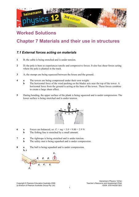
5 Dur<strong>in</strong>g bend<strong>in</strong>g, the upper surface of the plank is be<strong>in</strong>g squeezed <strong>and</strong> is under compression. The<br />
lower surface is be<strong>in</strong>g stretched <strong>and</strong> is under tension.<br />
6 a Forces are balanced, so: F t = mg = 3.0 × 9.80 = 2.9 N<br />
b The fish<strong>in</strong>g l<strong>in</strong>e is stretched by a small amount.<br />
7 a The tightrope is be<strong>in</strong>g stretched <strong>and</strong> is under tension.<br />
b The safety mat is be<strong>in</strong>g squashed <strong>and</strong> is under compression.<br />
8 a The ball is be<strong>in</strong>g squashed <strong>and</strong> is under compression.<br />
b, c<br />
F t F t F t<br />
F b<br />
F c<br />
F c<br />
F c<br />
F h<br />
F c<br />
He<strong>in</strong>emann Physics 12(3e)<br />
Copyright © Pearson Education Australia 2008<br />
Teacher’s Resource <strong>and</strong> Assessment Disk<br />
(a division of Pearson Australia Group Pty Ltd) ISBN 9781442501263<br />
1
<strong>Worked</strong> solutions<br />
<strong>Chapter</strong> 7 <strong>Materials</strong> <strong>and</strong> <strong>their</strong> <strong>use</strong> <strong>in</strong> structures<br />
9 a Forces are balanced, so: F t = mg = 80 × 9.80 = 780 N<br />
b The tensile force will stretch the rope.<br />
10<br />
He<strong>in</strong>emann Physics 12(3e)<br />
Copyright © Pearson Education Australia 2008<br />
Teacher’s Resource <strong>and</strong> Assessment Disk<br />
(a division of Pearson Australia Group Pty Ltd) ISBN 9781442501263<br />
2
<strong>Worked</strong> solutions<br />
<strong>Chapter</strong> 7 <strong>Materials</strong> <strong>and</strong> <strong>their</strong> <strong>use</strong> <strong>in</strong> structures<br />
7.2 Stress <strong>and</strong> strength<br />
1 a Force F = mg = 60 × 9.80 = 590 N<br />
Area A (<strong>in</strong> m 2 ) = πr 2 = π × 0.0050 2 = 7.9 × 10 –5 m 2<br />
Stress σ = F/A = 590/7.9 × 10 –5 = 7.5 × 10 6 Pa<br />
b Stress σ = F/A = 150/(0.015 2 ) = 6.5 × 10 5 Pa<br />
2 a Forces are balanced, so F t = F g = 900 × 9.80 = 8.8 × 10 3 N<br />
8820<br />
b Stress = F/A = = 1.9 × 10 7 Pa = 19 MPa<br />
2<br />
! ! 0.012<br />
3 Stress = F/A =<br />
4<br />
1.0!<br />
10<br />
! ! 0.00500<br />
2<br />
= 1.26 × 10 8 Pa<br />
4 Compressive strength of steel = 500 MPa (from table)<br />
Area A = πr 2 = π × (0.00500) 2 = 7.85 × 10 –5 m 2<br />
Maximum stress = 5.00 × 10 8 = F max /A<br />
F max = 5.00 × 10 8 × 7.85 × 10 –5 = 3.93 × 10 4 N = 39.3 kN<br />
5 Compressive strength of steel = 5000 MPa (from table)<br />
Maximum force = strength × area = 5.00 × 10 8 × 7.85 × 10 –5 = 39.3 kN<br />
Safety factor of 5 means that the maximum force under operat<strong>in</strong>g conditions must be 5 times<br />
lower: 39 300/5 = 7.9 kN<br />
6 a Area A = 3.0 cm 2 = 3.0 × 10 –4 m 2<br />
Maximum compressive stress = strength = 170 MPa (from table)<br />
Maximum compressive force = strength × area = 1.70 × 10 8 × 3.0 × 10 –4 = 5.0 × 10 4 N<br />
b Maximum tensile stress = strength = 130 MPa (from table)<br />
Maximum tensile force = strength × area = 1.30 × 10 8 × 3.0 × 10 –4 = 3.9 × 10 4 N<br />
7 a As the beam bends, the material along the centre is not under stress. This is a neutral<br />
zone.<br />
b As the beam bends, the bottom surface is under tension. Steel is weaker under tension, so<br />
more material is needed here.<br />
8 a F = mg = 1.0 × 10 5 × 9.80 = 9.8 × 10 5 N<br />
Compressive strength = 8.0 × 10 7 Pa<br />
Stress = F/A<br />
5<br />
9.80!<br />
10<br />
Area A = F/stress =<br />
7<br />
8.0!<br />
10<br />
= 1.2 × 10 –2 m 2<br />
A = 1.2 × 10 –2 = πr 2<br />
r = 0.063 m = 6.2 cm<br />
b F = mg = 1.0 × 10 5 × 9.80 = 9.8 × 10 5 N<br />
Compressive strength = 500 MPa (from table)<br />
Stress = F/A<br />
5<br />
9.8!<br />
10<br />
Area A = F/stress =<br />
8<br />
5.0!<br />
10<br />
= 2.0 × 10 –3 m 2<br />
A = 2.0 × 10 –3 = πr 2<br />
r = 0.025 m = 2.5 cm<br />
He<strong>in</strong>emann Physics 12(3e)<br />
Copyright © Pearson Education Australia 2008<br />
Teacher’s Resource <strong>and</strong> Assessment Disk<br />
(a division of Pearson Australia Group Pty Ltd) ISBN 9781442501263<br />
3
<strong>Worked</strong> solutions<br />
<strong>Chapter</strong> 7 <strong>Materials</strong> <strong>and</strong> <strong>their</strong> <strong>use</strong> <strong>in</strong> structures<br />
9 As this beam bends under the load, the underneath surface of the beam becomes stretched <strong>and</strong> is<br />
therefore under tension. S<strong>in</strong>ce concrete is weaker under tension than under compression, this<br />
surface is where cracks are more likely to appear.<br />
10 a Re<strong>in</strong>forced concrete comb<strong>in</strong>es the properties of the high tensile strength of steel with the<br />
high compressive strength of concrete to produce a composite material that is strong<br />
under both tension <strong>and</strong> compression.<br />
b The re<strong>in</strong>forc<strong>in</strong>g should be located near the top surface of the concrete. As the roots<br />
exp<strong>and</strong>, the concrete will bend upwards <strong>and</strong> the top surface will be under tension.<br />
Concrete is weak under tension <strong>and</strong> so re<strong>in</strong>forc<strong>in</strong>g is needed here.<br />
He<strong>in</strong>emann Physics 12(3e)<br />
Copyright © Pearson Education Australia 2008<br />
Teacher’s Resource <strong>and</strong> Assessment Disk<br />
(a division of Pearson Australia Group Pty Ltd) ISBN 9781442501263<br />
4
<strong>Worked</strong> solutions<br />
<strong>Chapter</strong> 7 <strong>Materials</strong> <strong>and</strong> <strong>their</strong> <strong>use</strong> <strong>in</strong> structures<br />
7.3 Stra<strong>in</strong><br />
1 a Equal, tension is 98 N <strong>in</strong> both<br />
b Th<strong>in</strong> due to its smaller cross-sectional area c Th<strong>in</strong> beca<strong>use</strong> it will stretch more.<br />
2 Stra<strong>in</strong> ε = Δl/l = 0.000127/0.200 = 6.35 × 10 –4<br />
3 Stra<strong>in</strong> ε = Δl/l<br />
Δl = ε × l = 0.00128 × 4.00 = 5.12 × 10 –3 m = 5.12 mm<br />
4 Stra<strong>in</strong> ε = Δl/l<br />
Δl = ε × l = 4.5 × 10 –4 × 7.00 = 3.15 × 10 –3 m = 3.15 mm<br />
5 Stra<strong>in</strong> ε = Δl/l<br />
Δl = ε × l = 0.00075 × 0.08000 = 6.00 × 10 –5 m = 6.00 × 10 –3 cm<br />
Marks will be: 8.000 + 0.00600 = 8.006 cm apart<br />
6 Stra<strong>in</strong> = 0.001 = 0.1%<br />
7 Stra<strong>in</strong> ε = Δl/l<br />
Δl = ε × l = 0.002 × 1.4 = 0.0028 m = 2.8 mm<br />
8 a<br />
F (kN) ΔL(mm) σ ( × 10 7 N m –2 ) ε (%)<br />
1.0 0.013 1.27 0.0065<br />
2.0 0.025 2.55 0.0125<br />
3.0 0.038 3.82 0.0190<br />
4.0 0.051 5.09 0.0255<br />
5.0 0.063 6.37 0.0315<br />
b<br />
! 7<br />
6.0"<br />
10<br />
c Gradient = rise/run = = 2.0 × 10 11 N m –2<br />
0.0003<br />
d When steel is subjected to different loads, the ratio stress/stra<strong>in</strong> is constant so σ = kε<br />
where k is a constant.<br />
9 From graph; when stress = 35 MPa, stra<strong>in</strong> = 0.018%<br />
He<strong>in</strong>emann Physics 12(3e)<br />
Copyright © Pearson Education Australia 2008<br />
Teacher’s Resource <strong>and</strong> Assessment Disk<br />
(a division of Pearson Australia Group Pty Ltd) ISBN 9781442501263<br />
5
<strong>Worked</strong> solutions<br />
<strong>Chapter</strong> 7 <strong>Materials</strong> <strong>and</strong> <strong>their</strong> <strong>use</strong> <strong>in</strong> structures<br />
784<br />
10 Stress σ = F/A = = 2.50 × 10 8 Pa<br />
2<br />
! ! 0.00100<br />
Assum<strong>in</strong>g that the stress/stra<strong>in</strong> ratio rema<strong>in</strong>s constant;<br />
gradient = rise/run = stress/stra<strong>in</strong><br />
2.0 × 10 11 8<br />
2.55!<br />
10<br />
=<br />
stra<strong>in</strong><br />
8<br />
2.55!<br />
10<br />
stra<strong>in</strong> = = 0.0013<br />
11<br />
2.0!<br />
10<br />
He<strong>in</strong>emann Physics 12(3e)<br />
Copyright © Pearson Education Australia 2008<br />
Teacher’s Resource <strong>and</strong> Assessment Disk<br />
(a division of Pearson Australia Group Pty Ltd) ISBN 9781442501263<br />
6
<strong>Worked</strong> solutions<br />
<strong>Chapter</strong> 7 <strong>Materials</strong> <strong>and</strong> <strong>their</strong> <strong>use</strong> <strong>in</strong> structures<br />
7.4 Young’s modulus<br />
1 a F<strong>in</strong>d stress where non-l<strong>in</strong>ear behaviour starts; 4.0 × 10 8 Pa<br />
b F<strong>in</strong>d stra<strong>in</strong> where non-l<strong>in</strong>ear behaviour beg<strong>in</strong>s; 0.0020<br />
c<br />
8<br />
4.0!<br />
10<br />
Gradient = rise/run =<br />
0.0020<br />
= 8.0 × 10 11 N m –2<br />
d The gradient of a stress-stra<strong>in</strong> graph is Young’s modulus<br />
e Strength = maximum stress = 6.0 × 10 8 Pa<br />
2 a Stra<strong>in</strong> at break<strong>in</strong>g po<strong>in</strong>t = 0.0050<br />
Stra<strong>in</strong> ε = Δl/l<br />
Δl = ε × l = 0.0050 × 1.0 = 0.0050 m = 5.0 mm<br />
b Stra<strong>in</strong> at elastic limit = 0.0020<br />
Stra<strong>in</strong> ε = Δl/l<br />
Δl = ε × l = 0.0020 × 1.0 = 0.0020 m = 2.0 mm<br />
3 a Area A = πr 2 = π × (0.0010) 2 = 3.1 × 10 –6 m 2<br />
1000<br />
Stress σ = F/A = = 3.2 × 10 8 Pa<br />
8<br />
3.1"<br />
10 !<br />
From graph, stra<strong>in</strong> = 1.6 × 10 –3<br />
Stra<strong>in</strong> ε = Δl/l<br />
Δl = ε × l = 1.6 × 10 –3 × 1.0 = 1.6 mm<br />
b Zero; the wire has not been stressed beyond the elastic limit, so will return to its orig<strong>in</strong>al<br />
length once the force has stopped act<strong>in</strong>g.<br />
4 a ductile<br />
b F t = mg = 153 × 9.80 = 1500 N<br />
1500<br />
Stress σ = F/A =<br />
6<br />
3.1"<br />
10 ! = 4.8 × 10 8 Pa<br />
From graph, stra<strong>in</strong> = 3.0 × 10 –3<br />
Stra<strong>in</strong> ε = Δl/l<br />
3.0 × 10 –3 = Δl/1.0<br />
Δl = 3.0 × 10 –3 m = 3.0 mm<br />
c No, s<strong>in</strong>ce the material does not behave elastically under this tensile stress.<br />
5000<br />
5 Stress σ = F/A = = 5.00 × 10 7 Pa<br />
4<br />
1.00"<br />
10 !<br />
! 3<br />
0.800"<br />
10<br />
Stra<strong>in</strong> ε = Δl/l =<br />
= 4.00 × 10 –4<br />
2.00<br />
7<br />
5.00"<br />
10<br />
E = stress/stra<strong>in</strong> =<br />
= 1.25 × 10 11 Pa<br />
4<br />
4.00"<br />
10 !<br />
6 a The higher the value of Young’s modulus, the stiffer the material.<br />
b Least flexible is tungsten as it has highest E value, then steel <strong>and</strong> f<strong>in</strong>ally alum<strong>in</strong>ium is<br />
most flexible.<br />
7 Stra<strong>in</strong> ε = 0.010<br />
E = σ/ε<br />
Stress σ = E × ε = 7.0 × 10 10 × 0.010 = 7.0 × 10 8 Pa<br />
He<strong>in</strong>emann Physics 12(3e)<br />
Copyright © Pearson Education Australia 2008<br />
Teacher’s Resource <strong>and</strong> Assessment Disk<br />
(a division of Pearson Australia Group Pty Ltd) ISBN 9781442501263<br />
7
<strong>Worked</strong> solutions<br />
<strong>Chapter</strong> 7 <strong>Materials</strong> <strong>and</strong> <strong>their</strong> <strong>use</strong> <strong>in</strong> structures<br />
F/A = 7.0 × 10 8<br />
F = 7.0 × 10 8 × (π × 0.0050 2 ) = 5.5 × 10 4 N<br />
8 a Stress at elastic limit is: σ = 1.0 × 10 8 Pa<br />
E = σ/ε<br />
8<br />
1.0!<br />
10<br />
ε = σ/E =<br />
10<br />
1.6!<br />
10<br />
= 6.25 × 10 –3<br />
Stra<strong>in</strong> ε = Δl/l<br />
6.25 × 10 –3 = Δl/0.40<br />
Δl = 0.0025 m = 2.5 mm<br />
b Tension, s<strong>in</strong>ce the tensile strength for bone is lower than the compressive strength for<br />
bone (from the table).<br />
c As we age, calcium loss ca<strong>use</strong>s the cross-sectional area of our bones to decrease. For any<br />
given load, therefore, the stress that the bones will experience will be greater <strong>and</strong> they<br />
will be more likely to fracture (so eat your dairy products!)<br />
9 Stra<strong>in</strong> ε = Δl/l = 0.00030/0.40 = 0.00075<br />
E = σ/ε<br />
Stress σ = E × ε = 1.6 × 10 10 × 0.00075 = 1.2 × 10 7 Pa<br />
10 a C, D; they break at the elastic limit.<br />
b A; it has the steepest gradient.<br />
c D; it has the smallest gradient.<br />
d B; it withst<strong>and</strong>s the greatest stress before fail<strong>in</strong>g.<br />
e A; it has the greatest plastic region.<br />
f A; it has the greatest ability to deform without break<strong>in</strong>g.<br />
He<strong>in</strong>emann Physics 12(3e)<br />
Copyright © Pearson Education Australia 2008<br />
Teacher’s Resource <strong>and</strong> Assessment Disk<br />
(a division of Pearson Australia Group Pty Ltd) ISBN 9781442501263<br />
8
<strong>Worked</strong> solutions<br />
<strong>Chapter</strong> 7 <strong>Materials</strong> <strong>and</strong> <strong>their</strong> <strong>use</strong> <strong>in</strong> structures<br />
7.5 Stra<strong>in</strong> energy <strong>and</strong> toughness<br />
1 a stra<strong>in</strong> = 0.20% = 2.0 × 10 –3<br />
Work done per cubic metre = area under stress-stra<strong>in</strong> graph = 0.5 × 2.0 × 10 –3 × 4.0 × 10 8<br />
= 4.0 × 10 5 J/m 3<br />
b<br />
c<br />
Stra<strong>in</strong> energy = area under graph × volume of material = 4.0 × 10 5 × 4.0 × 10 –5 = 16 J<br />
It is <strong>in</strong> the elastic region of the graph, so will resume its orig<strong>in</strong>al length <strong>and</strong> no energy will<br />
be transformed <strong>in</strong>to heat.<br />
2 a Area under graph up to stra<strong>in</strong> of 4.0 × 10 –3 = (1.0 × 10 8 × 1.0 × 10 –3 ) × 13.5 squares =<br />
1.35 × 10 6 J/m 3<br />
b Stra<strong>in</strong> energy = area under graph × volume of material = 1.35 × 10 6 × 4.0 × 10 –5 = 54 J<br />
c It is past the elastic limit, so the alloy will be permanently deformed <strong>and</strong> will heat up as it<br />
is stretched.<br />
3 a Po<strong>in</strong>t B is the fracture po<strong>in</strong>t, so the alloy will break.<br />
b Area under graph up to stra<strong>in</strong> of 5.0 × 10 –3 = (1.0 × 10 8 × 1.0 × 10 –3 ) × 19 squares = 1.9 ×<br />
10 6 J/m 3<br />
c Stra<strong>in</strong> energy = area under graph × volume of material = 1.9 × 10 6 × 4.0 × 10 –5 = 76 J<br />
4 In elastic deformation, all the stra<strong>in</strong> energy is returned by a material as it rega<strong>in</strong>s its <strong>in</strong>itial<br />
dimensions after the stra<strong>in</strong> is removed. For plastic deformation, some of the stra<strong>in</strong> energy will<br />
be transformed <strong>in</strong>to heat energy <strong>in</strong> alter<strong>in</strong>g the atomic structure of the material. Consequently,<br />
the material <strong>in</strong> this situation never rega<strong>in</strong>s its orig<strong>in</strong>al dimensions.<br />
5 a Stress σ = F/A = 1200/(π × 0.00200 2 ) = 9.55 × 10 7 Pa<br />
b This stress is under the elastic limit, so graph is straight l<strong>in</strong>e through orig<strong>in</strong>.<br />
E = stress/stra<strong>in</strong><br />
Stra<strong>in</strong> = stress/E = 9.55 × 10 7 /2.00 × 10 11 = 4.78 × 10 –4<br />
Area under stress-stra<strong>in</strong> graph = 0.5 × 4.78 × 10 –4 × 9.55 × 10 7 = 2.28 × 10 4 J/m 3<br />
c Stra<strong>in</strong> energy = area under graph × volume of material = 2.28 × 10 4 × (0.500 × π ×<br />
0.00200 2 ) = 0.14 J<br />
6 No, the rod fails at a po<strong>in</strong>t past the elastic limit where the behaviour of the material is nonl<strong>in</strong>ear.<br />
A stress–stra<strong>in</strong> graph is needed.<br />
7 Need to f<strong>in</strong>d: area under graph for P/area under graph for Q = 4.5 squares/3.0 squares = 1.5<br />
8 a F<strong>in</strong>d area under graph for P at failure = 9.5 squares × 1.0 × 10 8 × 1.0 × 10 –3 = 9.5 × 10 5<br />
J/m 3<br />
b F<strong>in</strong>d area under graph for Q at failure = 6.5 squares × 1.0 × 10 8 × 1.0 × 10 –3 =<br />
6.5 × 10 5 J/m 3<br />
9 Material P is tougher beca<strong>use</strong> it can absorb a greater amount of stra<strong>in</strong> energy per volume before<br />
fail<strong>in</strong>g (<strong>in</strong>dicated by area under stress–stra<strong>in</strong> graph).<br />
10 a Material P s<strong>in</strong>ce it has a greater value for Young’s modulus (<strong>in</strong>dicated by gradient).<br />
b Material P s<strong>in</strong>ce it experiences a greater stress value prior to fail<strong>in</strong>g.<br />
He<strong>in</strong>emann Physics 12(3e)<br />
Copyright © Pearson Education Australia 2008<br />
Teacher’s Resource <strong>and</strong> Assessment Disk<br />
(a division of Pearson Australia Group Pty Ltd) ISBN 9781442501263<br />
9
<strong>Worked</strong> solutions<br />
<strong>Chapter</strong> 7 <strong>Materials</strong> <strong>and</strong> <strong>their</strong> <strong>use</strong> <strong>in</strong> structures<br />
7.6 Forces <strong>in</strong> balance: Translational equilibrium<br />
1 For a body to be <strong>in</strong> translational equilibrium, the vector sum of the forces act<strong>in</strong>g on it must be<br />
zero. This situation applies to any stationary body, or one mov<strong>in</strong>g with constant velocity.<br />
Options A, B <strong>and</strong> D are therefore examples of translational equilibrium.<br />
2 a If your mass is 60 kg for example: F t = mg = 60 × 9.80 = 590 N (400–10 000 N)<br />
b If the car’s mass is 1000 kg for example: F t = mg = 1000 × 9.80 = 9.8 × 10 3 N (7000–<br />
12 000 N)<br />
c 10 L of water has a mass of 10 kg: F t = mg = 10 × 9.80 = 98 N (100 N)<br />
3 Total downwards force = 600 + 850 + (50 × 9.80) = 1940 N<br />
Assum<strong>in</strong>g weight is evenly distributed, upwards force provided by each cable is: F c = 1940/4 =<br />
485 N<br />
4 Total downwards force on beam = (1000 + 1500 + 2000 + 500) × 9.80 = 4.9 × 10 4 N<br />
Total upwards force on beam = F X + F Y = 4.9 × 10 4 N<br />
F Y = 4.9 × 10 4 – 2.0 × 10 4 = 2.9 × 10 4 N upwards<br />
5 Total work<strong>in</strong>g load = 5000 × 9.80 + 20,000 × 9.80 = 245,000 N<br />
Work<strong>in</strong>g load for each pillar = 245 000/2 = 123 000 N<br />
Given safety factor of 8, each pillar must be able to withst<strong>and</strong> maximum load of: 8 × 123 000 =<br />
9.8 × 10 5 N upwards<br />
6 Downwards force on sign = 5.0 × 9.80 = 49 N<br />
Each vertical component of the tension forces <strong>in</strong> wires is equal to 24.5 N.<br />
F t = 24.5/cos40° = 32 N<br />
7 Add<strong>in</strong>g the 3 vectors <strong>and</strong> form<strong>in</strong>g a force triangle gives: F g = 2 × 40 × s<strong>in</strong>40° = 51 N (or <strong>use</strong><br />
s<strong>in</strong>e rule)<br />
Mass m = 5.2 kg<br />
8 Total downwards force on wire is : F g = 90 × 9.80 = 880 N<br />
Each side of the cable is therefore provid<strong>in</strong>g an upwards force of 440 N.<br />
Us<strong>in</strong>g a force triangle gives: F t = 440/s<strong>in</strong>5° = 5.0 kN<br />
9 a Add<strong>in</strong>g the forces gives a right angled force triangle with a vertical weight force of 980<br />
N. Us<strong>in</strong>g this, it can be determ<strong>in</strong>ed that:<br />
F A = 980/s<strong>in</strong>60° = 1.13 × 10 3 N<br />
F B = 980/tan60° = 565 N<br />
b Cable A is more likely to break beca<strong>use</strong> it is under greater stress.<br />
c Stress σ(A) = F/A = 1.13 × 10 3 /1.5 × 10 –6 = 750 MPa<br />
Stress σ(B) = F/A = 565/1.5 × 10 –6 = 380 MPa<br />
d No, the stress <strong>in</strong> each wire is lower than the tensile strength of steel (820 MPa).<br />
10 Add<strong>in</strong>g the forces gives a right-angled force triangle with a vertical weight force of 1000 N.<br />
Us<strong>in</strong>g this, it can be determ<strong>in</strong>ed that:<br />
F A = 980/s<strong>in</strong>30° = 1.9 × 10 3 N<br />
F B = 980/tan30° = 1.7 × 10 3 N<br />
Stress σ(A) = F/A = 1.9 × 10 3 /1.5 × 10 –6 = 1300 MPa<br />
Stress σ(B) = F/A = 1.7 × 10 3 /1.5 × 10 –6 = 1100 MPa<br />
These stresses are both greater than the tensile strength of steel, so both cables would fail.<br />
He<strong>in</strong>emann Physics 12(3e)<br />
Copyright © Pearson Education Australia 2008<br />
Teacher’s Resource <strong>and</strong> Assessment Disk<br />
(a division of Pearson Australia Group Pty Ltd) ISBN 9781442501263<br />
10
<strong>Worked</strong> solutions<br />
<strong>Chapter</strong> 7 <strong>Materials</strong> <strong>and</strong> <strong>their</strong> <strong>use</strong> <strong>in</strong> structures<br />
7.7 Torque<br />
1 a The axis of rotation is the sp<strong>in</strong>dle. The size of the lever arm is approximately 3 cm.<br />
b The axis of rotation is the front wheel axle. The size of the lever arm is usually around<br />
1 m.<br />
c The axis of rotation at the end of the tweezers. The size of the lever arm is usually a few<br />
centimetres.<br />
d The axis of rotation is where the screwdriver is <strong>in</strong> contact with the rim of the t<strong>in</strong>. The size<br />
of the lever arm is usually around 15–30 cm.<br />
2 a The magnitude of the torque produced by a given force is proportional to the length of the<br />
lever arm. By push<strong>in</strong>g the door at the h<strong>and</strong>le, rather than the middle, the length to the<br />
lever arm is <strong>in</strong>creased.<br />
b A crowbar can be <strong>use</strong>d to generate a large torque beca<strong>use</strong> the force can be applied at a<br />
large distance from the pivot.<br />
3 Torque provided by Renee is: τ = F × r = 392 × 2.25 = 882 N m<br />
4 Torque must exceed 400 N m, so: F × r = 400<br />
F × 1.6 = 400<br />
F = 400/1.6 = 250 N<br />
5 a Weight force of load = mg = 2500 × 9.80 = 24 500 N<br />
τ = F × r = 24 500 × 20 = 4.9 × 10 5 N m<br />
b The crane will have a counterweight provid<strong>in</strong>g an opposite torque.<br />
6 a τ = F × r = 9.8 × 0.50 = 4.9 N m<br />
b τ = F × r = 9.8 × 1.0 = 9.8 N m<br />
c τ = F × rs<strong>in</strong>θ = 9.8 × 1.0 × s<strong>in</strong>30° = 4.9 N m<br />
7 The long pole with the heavy weight at the end can be <strong>use</strong>d to provide a large counter-torque<br />
should the performer overbalance. Only a small movement of the pole is need to balance the<br />
torque produced by the performers body when they overbalance.<br />
8 It will not work beca<strong>use</strong> the centre of mass lies outside the base of support. To make the design<br />
work, the bench or supports should be moved so that the centre of gravity is between the<br />
supports. . Otherwise, he could <strong>use</strong> bolts to attach the beam to the left-h<strong>and</strong> support.<br />
9 a The weight of the suitcase will produce a torque about a pivot po<strong>in</strong>t around the base of<br />
the sp<strong>in</strong>e which will tend to rotate your torso to the right. You compensate for this by<br />
lean<strong>in</strong>g to the left or extend<strong>in</strong>g your left arm.<br />
b Force = mg = 14 × 10 = 140 N m<br />
Assume that you are hold<strong>in</strong>g the suitcase approximately 0.5 m from sp<strong>in</strong>e.<br />
τ = F × r ≈ 140 × 0.50 ≈ 70 N m<br />
10 a Weight of skip: F g = mg = 3500 × 9.80 = 3.4 × 10 4 N<br />
b The effective lever arm rema<strong>in</strong>s at 15 m throughout, so the torque does not change.<br />
c τ = F × rs<strong>in</strong>θ = 3.43 × 10 4 × 25 × s<strong>in</strong>37° = 5.1 × 10 5 N m clockwise about the pivot.<br />
(or simply f<strong>in</strong>d: τ = F × r = 3.43 × 10 4 × 15 = 5.1 × 10 5 N m clockwise about the pivot.)<br />
He<strong>in</strong>emann Physics 12(3e)<br />
Copyright © Pearson Education Australia 2008<br />
Teacher’s Resource <strong>and</strong> Assessment Disk<br />
(a division of Pearson Australia Group Pty Ltd) ISBN 9781442501263<br />
11
<strong>Worked</strong> solutions<br />
<strong>Chapter</strong> 7 <strong>Materials</strong> <strong>and</strong> <strong>their</strong> <strong>use</strong> <strong>in</strong> structures<br />
7.8 Structures <strong>in</strong> translational <strong>and</strong> rotational equilibrium<br />
1 Torque produced by first child is: τ = F × r = 200 × 1.2 = 240 N m<br />
Torque produced by second child is: τ = F × r = mg × 1.5 = 240 N m<br />
mg = 240/1.5 = 160 N<br />
mass m = 16 kg<br />
2 To generate less torque, the adult should sit near the pivot. The child should sit at end of beam.<br />
3 = (19.6 × 0.25) + (49 × 0.50) = 29 N m<br />
4 a Torque of cable act<strong>in</strong>g around axis is: τ = F t × 10s<strong>in</strong>30° = 5 × F t<br />
b F t (v) = F t s<strong>in</strong>30°, F t (h) = F t cos30°<br />
c Assume that each cable supports half the weight of the bridge i.e. 3430 N<br />
Tak<strong>in</strong>g torques around the axis: (F t s<strong>in</strong>30° × 10) – (3430 × 5.0) = 0<br />
F t = 17 200/5.0 = 3440 = 3.4 × 10 3 N<br />
5 Call support forces F L <strong>and</strong> F R .<br />
Total of downwards forces = (100+150+200+50) × 9.80 = 4900 N<br />
Total of upwards forces: F L + F R = 4900 N<br />
Tak<strong>in</strong>g torques around left-h<strong>and</strong> end:<br />
–(980 × 3.0) – (490 × 5.0) – (1470 × 7.0) – (1960 × 8.5) + (F R × 10) = 0<br />
F R × 10 = 32,300<br />
F R = 3200 N = 3.2 kN up<br />
F L = 4900 – 3200 = 1700 N = 1.7 kN up<br />
6 The beam <strong>and</strong> the tra<strong>in</strong> have a weight of 49 000 N each.<br />
Tak<strong>in</strong>g torques around end X: –(4.9 × 10 4 × d) – (4.9 × 10 4 × 10) + (30 600 × 20) = 0<br />
d = 2.5 m from end X or 17.5 m from end Y.<br />
7 a τ = F × rs<strong>in</strong>θ = 157 × 2.4 × s<strong>in</strong>25° = 160 N m<br />
b τ = F × rs<strong>in</strong>θ = 490 × 1.2 × s<strong>in</strong>25° = 250 N m<br />
c τ = F × rs<strong>in</strong>θ = 490 × 3.6 × s<strong>in</strong>25° = 750 N m<br />
8 a The vector sum of all the forces is zero i.e. F X + F Y +F g = 0<br />
Tak<strong>in</strong>g the magnitudes of these forces gives: F X + F Y = 900 × 9.80 = 8,820 N<br />
b (F Y × 1.8) – (8820 × 2.0) = 0<br />
c F Y = 17 640/1.8 = 9,800 N = 9.8 kN up<br />
d –(F X × 1.8) + (8820 × 0.2) = 0<br />
e F X = 1760/1.8 = 980 N down<br />
Y is be<strong>in</strong>g squashed beneath the beam <strong>and</strong> so is under compression. X is exert<strong>in</strong>g a<br />
downwards force on the beam <strong>and</strong> so is under tension.<br />
9 a Tak<strong>in</strong>g magnitudes of forces: F L + F R = 686 + 196 = 882 N<br />
Tak<strong>in</strong>g torques around left-h<strong>and</strong> end: (686 × 1.50) + (196 × 2.50) – (F R × 5.00) = 0<br />
F R = 1520/5.00 = 300 N up<br />
F L = 882 – 300 = 580 N up<br />
b Tak<strong>in</strong>g torques around left-h<strong>and</strong> end: (686 × d) + (196 × 2.50) – (325 × 5.00) = 0<br />
d = 1135/686 = 1.7 m from left-h<strong>and</strong> end.<br />
He<strong>in</strong>emann Physics 12(3e)<br />
Copyright © Pearson Education Australia 2008<br />
Teacher’s Resource <strong>and</strong> Assessment Disk<br />
(a division of Pearson Australia Group Pty Ltd) ISBN 9781442501263<br />
12
<strong>Worked</strong> solutions<br />
<strong>Chapter</strong> 7 <strong>Materials</strong> <strong>and</strong> <strong>their</strong> <strong>use</strong> <strong>in</strong> structures<br />
10 a i The three forces act<strong>in</strong>g on the left-h<strong>and</strong> cantilever are the weight of the beam<br />
(3920 N), the force from pillar A (F A ) act<strong>in</strong>g downwards <strong>and</strong> the force from pillar<br />
B (F B ) act<strong>in</strong>g upwards<br />
F A + 3920 = F B<br />
Tak<strong>in</strong>g torques around the left-h<strong>and</strong> end of the left cantilever:<br />
(F B × 1.2) – (3920 × 1.5) = 0<br />
F B = 5880/1.2 = 4.9 kN up<br />
So: F A = 980 N down<br />
By symmetry: F C = 4.9 kN up <strong>and</strong> F D = 980 N down<br />
ii The force that the pedestrian F P exerts on the end of the cantilever is 350 N down.<br />
F A + 4000 + 343 = F B<br />
Tak<strong>in</strong>g torques around the left-h<strong>and</strong> end of the left cantilever:<br />
(F B × 1.2) – (4000 × 1.5) – (343 × 3.0)= 0<br />
F B = 7030/1.2 = 5860 = 5.9 kN up<br />
So: F A = 1520 N = 1.5 kN down<br />
By symmetry: F C = 5.9 kN up <strong>and</strong> F D = 1.5 kN down<br />
b As the woman walks from A to B, the force act<strong>in</strong>g <strong>in</strong> pillar A decreases <strong>and</strong> the force<br />
act<strong>in</strong>g <strong>in</strong> B <strong>in</strong>creases. When the woman passes po<strong>in</strong>t B <strong>and</strong> cont<strong>in</strong>ues on to po<strong>in</strong>t P, the<br />
forces <strong>in</strong> both A <strong>and</strong> B <strong>in</strong>crease, <strong>in</strong> order to produce a greater torque to counterbalance the<br />
<strong>in</strong>crease <strong>in</strong> torque as she moves to po<strong>in</strong>t P.<br />
11 The weight of the beam is 49 N.<br />
Tak<strong>in</strong>g torques around the left-h<strong>and</strong> end of the beam: (F t s<strong>in</strong>45° × 1.2) – (49 × 0.9) = 0<br />
F t = 44.1/0.85 = 52 N<br />
12 a F h = 784s<strong>in</strong>30° = 390 N<br />
F v = 784cos30° = 680 N<br />
b Tak<strong>in</strong>g torques around base of post: (F t × 1.0) – (392 × 0.85) = 0<br />
F t = 330 N<br />
He<strong>in</strong>emann Physics 12(3e)<br />
Copyright © Pearson Education Australia 2008<br />
Teacher’s Resource <strong>and</strong> Assessment Disk<br />
(a division of Pearson Australia Group Pty Ltd) ISBN 9781442501263<br />
13
<strong>Worked</strong> solutions<br />
<strong>Chapter</strong> 7 <strong>Materials</strong> <strong>and</strong> <strong>their</strong> <strong>use</strong> <strong>in</strong> structures<br />
<strong>Chapter</strong> review<br />
1 Strength = maximum stress prior to failure = 350 × 10 6 = 350 MPa so D is the correct option.<br />
2 Elastic limit = stress at end of non-l<strong>in</strong>ear region = 300 × 10 6 N m –2 so C is correct.<br />
3 E = gradient of elastic region = 300 × 10 6 /1.5 × 10 –3 = 2.0 × 10 11 N m –2 so C is correct.<br />
4 First, f<strong>in</strong>d area up to elastic limit X.<br />
Area = ½ × 1.5 × 10 –3 × 300 × 10 6 = 225 000 J m –3<br />
Energy = area × volume of wire = 225 000 × (1.5 × 2.0 × 10 –6 ) = 0.675 J so D is correct.<br />
5 First f<strong>in</strong>d area up to po<strong>in</strong>t Y.<br />
Area (28 squares) = 28 × 50 × 10 6 × 1.0 × 10 –3 = 1 400 000 J m –3<br />
Energy = area × volume = 1 400 000 × (1.5 × 2.0 × 10 –6 ) = 4.2 J so E is correct.<br />
6 This is plastic behaviour so B.<br />
7 Weight F g = 7.5 × 9.8 = 74 N, distance r = 3.0 m<br />
Torque τ = (74cos65°) × 3.0 = 94 N m so E is correct.<br />
8 Torque τ = F × r = (60 × 9.8 × cos65°) × 2.0 = 500 N m so A is correct.<br />
9 Balanced forces so F t = mg = 4500 × 9.8 = 4.4 × 10 4 N m = 44 kN. B is the correct option.<br />
10 The forces are aga<strong>in</strong> balanced so F t = mg. B is correct.<br />
11 a E = stress/stra<strong>in</strong> = F/A / Δl/l =<br />
1000<br />
! ! 0.0010<br />
0.00049 0.20<br />
2<br />
= 1.3 × 10 11 Pa<br />
b % stra<strong>in</strong> = Δl/l × 100 = 0.49/200 × 100 = 0.25%<br />
c Young’s modulus depends only on the properties of the material itself whereas the spr<strong>in</strong>g<br />
constant depends on the nature of the material as well as its length <strong>and</strong> thickness.<br />
12 a Stress at elastic limit = F/A = 2.0 × 10 6 Pa<br />
5<br />
1.0!<br />
10<br />
2<br />
!r<br />
= 2.0 × 10 6<br />
r 2 5<br />
1.0!<br />
10<br />
=<br />
6<br />
! ! 2.0!<br />
10<br />
= 0.0159<br />
r = 0.125 m = 12.5 cm<br />
b<br />
6<br />
2.0!<br />
10<br />
Stra<strong>in</strong> at elastic limit = stress/E =<br />
10<br />
2.0!<br />
10<br />
= 1.0 × 10 –4<br />
Area under graph to elastic limit = 0.5 × 2.0 × 10 6 × 1.0 × 10 –4 = 100 J m –3<br />
Energy = area under graph × volume of material = 100 × 4.0 = 400 J<br />
c Concrete is much stronger under compression than tension. A column is always under<br />
compression, whereas a beam can be under both compression <strong>and</strong> tension.<br />
d The concrete is poured over a lattice of steel rods <strong>and</strong> sets around them. This results <strong>in</strong> the<br />
formation of a composite material called re<strong>in</strong>forced concrete, which is suitable for <strong>use</strong> <strong>in</strong><br />
beams <strong>and</strong> floor<strong>in</strong>g.<br />
13 Maximum stress = 3.0 × 10 8 Pa from graph<br />
He<strong>in</strong>emann Physics 12(3e)<br />
Copyright © Pearson Education Australia 2008<br />
Teacher’s Resource <strong>and</strong> Assessment Disk<br />
(a division of Pearson Australia Group Pty Ltd) ISBN 9781442501263<br />
14
<strong>Worked</strong> solutions<br />
<strong>Chapter</strong> 7 <strong>Materials</strong> <strong>and</strong> <strong>their</strong> <strong>use</strong> <strong>in</strong> structures<br />
14 a When stress = 2.0 × 10 8 Pa, stra<strong>in</strong> = 2.0 × 10 –3 from graph.<br />
Stra<strong>in</strong> ε = Δl/l<br />
2.0 × 10 –3 = Δl/0.0800<br />
Δl = 1.6 × 10 –4 m = 0.16 mm<br />
b Maximum stress = 3.0 × 10 8 = F/A<br />
F = 3.0 × 10 8 × 1.0 × 10 –4 = 3.0 × 10 4 N<br />
c Stress at elastic limit = 2.0 × 10 8 = F/A<br />
F = 2.0 × 10 8 × 1.0 × 10 –4 = 2.0 × 10 4 N<br />
Safety factor = 5, so maximum force under work<strong>in</strong>g operations must be 5 times lower<br />
4<br />
2.0!<br />
10<br />
than force at elastic limit: Maximum force = = 4.0 kN<br />
5<br />
15 Area under graph up to break<strong>in</strong>g po<strong>in</strong>t = 16.4 squares × 0.5 × 10 8 × 1.0 × 10 –3 = 8.2 × 10 5 J m –3<br />
Volume of material = 1.0 × 10 –4 × 0.0800 = 8.0 × 10 –6 m 3<br />
Stra<strong>in</strong> energy = area under graph × volume of material = 8.2 × 10 5 × 8.0 × 10 –6 = 6.6 J<br />
16 a Stiffness is the resistance of the material to be<strong>in</strong>g stretched or compressed.<br />
b Rank <strong>in</strong> order of Young’s modulus: nylon, alum<strong>in</strong>ium, steel<br />
c Steel: E = 2.0 × 10 11 = σ/ε<br />
5<br />
1.0!<br />
10<br />
Stra<strong>in</strong> =<br />
11<br />
2.0!<br />
10<br />
= 5.0 × 10 –7<br />
Stra<strong>in</strong> energy per unit volume = area under graph = 0.5 × 1.0 × 10 5 × 5.0 × 10 –7 =<br />
0.025 J m –3<br />
Alum<strong>in</strong>ium: E = 7.0 × 10 10 = σ/ε<br />
5<br />
1.0!<br />
10<br />
Stra<strong>in</strong> =<br />
10<br />
7.0!<br />
10<br />
= 1.5 × 10 –6<br />
Stra<strong>in</strong> energy per unit volume = area under graph = 0.5 × 1.0 × 10 5 × 1.5 × 10 –6 =<br />
0.071 J m –3<br />
Nylon: E = 7.0 × 10 8 = σ/ε<br />
5<br />
1.0!<br />
10<br />
Stra<strong>in</strong> = = 1.4 × 10 –4<br />
8<br />
7.0!<br />
10<br />
Stra<strong>in</strong> energy per unit volume = area under graph = 0.5 × 1.0 × 10 5 × 1.4 × 10 –4 = 7.0 J m –<br />
3<br />
d<br />
The area under the graph up to the po<strong>in</strong>t of fracture is greater for steel than it is for<br />
alum<strong>in</strong>ium.<br />
17 The weight of the globe is 15 N. Let us call the left-h<strong>and</strong> wire A <strong>and</strong> the wire on the right B.<br />
Add<strong>in</strong>g the 3 force vectors gives a right-angle triangle. This can be <strong>use</strong>d to determ<strong>in</strong>e F A <strong>and</strong><br />
F B .<br />
F A = 15/s<strong>in</strong>40° = 23 N<br />
F B = 15/tan40° = 18 N<br />
18 Tak<strong>in</strong>g the magnitudes of the forces: F L + F R = 58.8 + 19.6 + 127.4 + 9 8 = 303.8 N<br />
Tak<strong>in</strong>g torques around the left end of the beam:<br />
–(58.8 × 2) – (147 × 5.0) – (198 × 7.0) + (F R × 10.0) = 0<br />
F R = 1540/10.0 = 154 N<br />
F L = 310 – 157 = 150 N<br />
19 a Torque created by load is: τ = F × r = (1.5 × 10 3 × 9.8) × 25 = 3.7 × 10 5 N m<br />
Desired torque created by counterweight is: τ = (20 000 × 9.80) × r = 3.7 × 10 5<br />
He<strong>in</strong>emann Physics 12(3e)<br />
Copyright © Pearson Education Australia 2008<br />
Teacher’s Resource <strong>and</strong> Assessment Disk<br />
(a division of Pearson Australia Group Pty Ltd) ISBN 9781442501263<br />
15
<strong>Worked</strong> solutions<br />
<strong>Chapter</strong> 7 <strong>Materials</strong> <strong>and</strong> <strong>their</strong> <strong>use</strong> <strong>in</strong> structures<br />
b<br />
Location of counterweight is r = 1.9 m from pivot.<br />
This reduces the torque act<strong>in</strong>g on the crane mak<strong>in</strong>g it less likely to topple over.<br />
20 a τ = F × r = 250 × 1.0 = 250 N m –1<br />
b Y, the force will ca<strong>use</strong> the barrier to bend slightly caus<strong>in</strong>g compression at X <strong>and</strong> tension<br />
at Y. Concrete is weaker under tension, so the barrier is more likely to crack at Y.<br />
c The steel rods are strong under tension <strong>and</strong> reduce the amount of bend<strong>in</strong>g <strong>and</strong> crack<strong>in</strong>g<br />
that occurs at Y.<br />
He<strong>in</strong>emann Physics 12(3e)<br />
Copyright © Pearson Education Australia 2008<br />
Teacher’s Resource <strong>and</strong> Assessment Disk<br />
(a division of Pearson Australia Group Pty Ltd) ISBN 9781442501263<br />
16