Water cooled screw chillers - McQuay
Water cooled screw chillers - McQuay
Water cooled screw chillers - McQuay

You also want an ePaper? Increase the reach of your titles
YUMPU automatically turns print PDFs into web optimized ePapers that Google loves.
0<br />
Product Manual<br />
803 B – 04/11 D<br />
Data: November 2004<br />
Supersedes: 803 B-02/09 C<br />
<br />
<br />
<br />
<br />
<br />
<br />
<strong>McQuay</strong> is participating in the Eurovent Certification Programme.<br />
Product are as listed in the Eurovent Directory of Certified Products<br />
and on the web site www.eurovent-certification.com
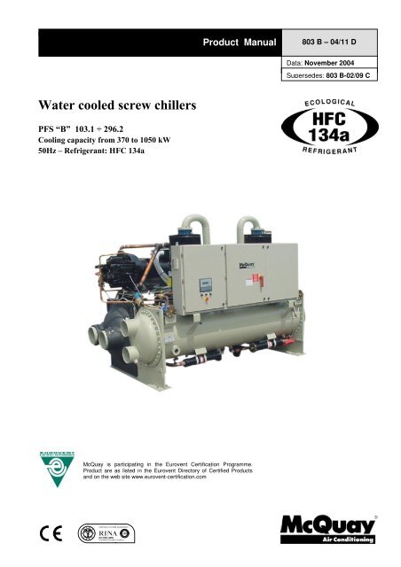
New water <strong>cooled</strong> <strong>screw</strong> <strong>chillers</strong> <strong>McQuay</strong> PFS “B”<br />
<strong>McQuay</strong> International introduces their newest water <strong>cooled</strong> <strong>screw</strong> <strong>chillers</strong> equipped with new single <strong>screw</strong><br />
compressors.<br />
<strong>McQuay</strong> water <strong>cooled</strong> PFS <strong>chillers</strong> equipped with 1 or 2 <strong>McQuay</strong> <strong>screw</strong> compressors are a new range of the unit<br />
using the StarGate TM single <strong>screw</strong> compressors. They are manufactured by <strong>McQuay</strong> to satisfy the requirements of<br />
the consultants and the end user. <strong>McQuay</strong> PFS units are designed to minimise energy costs while maximising the<br />
refrigeration capacities. Once again <strong>McQuay</strong> has developed a line of <strong>chillers</strong> unsurpassed in performance and<br />
quality that will meet the most stringent requirements of comfort cooling, ice storage and process applications.<br />
<strong>McQuay</strong>’s chiller design experience, combined with outstanding features makes the PFS chiller unmatched in the<br />
industry.<br />
Customer benefits<br />
Design for every kind of requirement<br />
Compared with competitors, PFS water <strong>cooled</strong> chiller offers surprising performance. PFS dual compressor unit<br />
(with a single refrigerant circuit) takes full advantage of the total heat transfer surface over the use of two separate<br />
refrigerant circuits when only one compressor is required to satisfy the thermal load.<br />
<strong>McQuay</strong> has answered the challenge to create a reliable, energy efficient, environmentally safe with the<br />
introduction of the new PFS <strong>screw</strong> compressor water-<strong>cooled</strong> chiller.<br />
Lower noise – higher flexibility<br />
The <strong>McQuay</strong> original compressor design with a single <strong>screw</strong> and twin rotors allows a constant gas flow. This<br />
compression process completely eliminates gas pulsations. The oil injection also results in significant mechanical<br />
noise reduction.<br />
The twin gas compressor discharge chambers are designed to act as attenuators, based on the harmonic wave<br />
principle with destructive interference, thus always resulting equal to zero. The extremely low noise compressor<br />
performance affords the use of PFS chiller for all applications.<br />
The reduced number of vibrations produced from the PFS <strong>chillers</strong> offers a surprisingly quiet operation eliminating<br />
the noise transmission through the structure and the chilled water piping system.<br />
Infinitely variable capacity control<br />
Cooling capacity control is infinitely variable by means of a capacity slide controlled by microprocessor system.<br />
Each unit has infinitely variable capacity control down to 12.5% (two compressors units), to 25% (one compressor<br />
units). This modulation allows the compressor capacity to exactly match the building cooling load. The result is a<br />
decrease in chiller energy costs, particularly at the part-load conditions at which the chiller operates most of the<br />
time. In order to optimize control sequence, each compressor load (and unload) from 95 to 100 % of its capacity<br />
by one step.<br />
Unmatched serviceability<br />
Field serviceability has not been sacrificed. Inspection covers allows visual inspection of the main <strong>screw</strong> and<br />
gaterotors. Suction valves allow easy isolation and field servicing of this unit.<br />
Outstanding reliability features<br />
Full factory testing of all the units ensures a trouble free start-up. Extensive test makes certain that each safety<br />
and operating control is properly adjusted, and operates correctly.<br />
803 B – 04/07 04/11 D – pag. 2/24
General characteristics<br />
Ecological HCF 134a refrigerant<br />
<strong>McQuay</strong> has designed and optimized Stargate TM compressors to operate with HFC 134a, ecological refrigerant<br />
with zero ODP (Ozone Depletion Potential) and very low GWP (Global Warming Potential) that means low value of<br />
the “direct effect” in the formula of TEWI (Total Equivalent<br />
Warming Impact).<br />
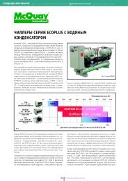
Screw compressors<br />
The newest Stargate TM single-<strong>screw</strong> compressor has a well<br />
balanced compression mechanism which cancels the <strong>screw</strong><br />
rotor load in both the radial and axial directions. Inherent to<br />
the basic single-<strong>screw</strong> compressor design is the virtually<br />
load-free operation, that gives main bearing design life of 3-4<br />
times greater than twin-<strong>screw</strong>s, and eliminates expensive<br />
and complicated thrust balancing schemes. The two exactly<br />
opposed gaterotors create two exactly opposed compression<br />
cycles. Compression is made at the lower and upper parts of<br />
the <strong>screw</strong> rotor at the same time, thus cancelling the radial<br />
loads. Also, both ends of the <strong>screw</strong> rotor are subjected to<br />
suction pressure only, which cancels the axial loads and<br />
eliminates the huge thrust loads inherent in twin-<strong>screw</strong><br />
compressors.<br />
Oil injection is used for these compressors in order to get<br />
high COP at high condensing pressure. PFS units are<br />
provided with an high efficiency oil separator to maximise oil<br />
extraction.<br />
Compressors have a infinitely variable capacity control down<br />
to 25% of its total capacity. This control is made by means of<br />
capacity slides controlled by microprocessors.<br />
Standard start is star-delta type; Soft start type is available<br />
(as option) in order to have lower inrush current.<br />
Evaporator<br />
Flooded shell-and-tube evaporator operating with refrigerant in shell and water in tubes. Replaceable water tubes<br />
are fabricated from integral finned copper and mechanically bonded to steel tube sheets. The evaporator is PED<br />
designed, constructed, inspected and stamped. <strong>Water</strong> side working pressure is designed for 10,5 bar. Vessels<br />
include 1” FPT spring loaded pressure relief valves. Shell and non-connection water heads are insulated with 3/4”<br />
thick closed cell insulation. Standard configuration on water connections side is 2 passes.<br />
Condenser<br />
Shell-and-tube type operating with refrigerant in shell and water in tubes. Replaceable water tubes are fabricated<br />
from integral finned copper and mechanically bonded to steel tube sheets. Condenser is designed to conform<br />
PED. <strong>Water</strong> side working pressure is designed for 10.5 bar. Standard configuration on water connections side is 2<br />
passes.<br />
Operative efficiency<br />
The majority of comfort cooling systems operate at 60% or less of building design kW for most of the year. A great<br />
number of those operating hours occur between 50% and 60% design cooling capacity. For that reason, PFS<br />
chiller was designed to obtain excellent part load performance. This is achieved by a combination of individual<br />
component features that include compressor design, operating control, double heat transfer surface with only one<br />
compressor running (dual compressors unit), refrigerant flow control.<br />
803 B – 04/11 D – pag. 3/24
Servo Controlled modulating liquid level regulators<br />
PFS are equipped with a modulating servo-controlled main expansion valve type controlled by a pilot float valve<br />
type to perfectly modulate refrigerant flow to the evaporator, proportionally to the required capacity. This ensures a<br />
stable regulation and economic operation, because pressure and temperature variations are strongly reduced.<br />
Electrical panel<br />
Power and control are located into two sections of the main panel that is manufactured to insure protection for all<br />
weather conditions.<br />
The power panel is fitted with a interlocked door main isolator to prevent access while power supply is on.<br />
Electrical panel is IP43.<br />
Power section includes - The power section includes contactors, all compressors fuses, and control circuit<br />
transformer. Additional space is provided for an easy installation of the various optional accessories provided to<br />
enhance the PFS units capabilities.<br />
Certifications<br />
All the PFS units are CE marked (89/392). <strong>McQuay</strong> Italia obtained ISO 9001:2000.<br />
<strong>Water</strong> content in cooling circuits<br />
The <strong>cooled</strong> water distribution circuits should have a minimum water content to avoid excessive compressors start<br />
and stop.<br />
In fact, each time the compressor starts up, an excessive quantity of oil goes from the compressor sump and<br />
simultaneously there is a rise in the temperature of the compressor motor’s stator due to the inrush current during<br />
the start-up. To prevent damage to the compressors, <strong>McQuay</strong> has envisaged the application of a device to limit<br />
frequent stops and restarts.<br />
During the span of one hour there will be no more than 6 starts of the compressor. The plant side should therefore<br />
ensure that the overall water content allows a more constant functioning of the unit and consequently greater<br />
environmental comfort. The minimum installation water content envisaged should be calculated with a certain<br />
approximation using this simplified formula:<br />
(1) Q = 35,83 X<br />
P (kW)<br />
∆T(<br />
° C)<br />
X<br />
N<br />
1<br />
where:<br />
Q = Minimum content of the plant expressed in litres<br />
P = Cooling capacity of the plant expressed in kW<br />
∆T = Entering/leaving water temperature difference of the evaporator expressed in °C<br />
N = Number of compressors.<br />
For a more accurate determination of the quantity of water, it is advisable to contact the designer of the plant.<br />
803 B – 04/11 D – pag. 4/24
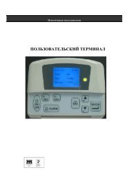
Microtech II Plus controller<br />
Microtech II Plus device is installed as standard on all the units; it can be used to alter unit set points and control<br />
commands. A display illustrates the machine's operating status and programable parameters (setpoints) e.g.<br />
temperatures and pressures of fluids (water, refrigerant). Device controls maximise the <strong>McQuay</strong> <strong>chillers</strong> energy<br />
efficiency and reliability characteristics. It uses sophisticated software with predictive logic to select the most<br />
energy efficient combination of compressor. The compressors are automatically rotated to ensure equal operating<br />
hours. Microprocessor device protects critical components in response to external signals from its system sensors<br />
measuring: motor temperatures, refrigerant gas and oil pressures, electrical supply and evaporator.<br />
Control section - main features:<br />
• Management of the compressor capacity slide according to the distributed multiprocessor logic system<br />
• Chillers enabled to work in partial failure condition thanks to the distributed multiprocessor logic system<br />
• Full routine operation at condition of:<br />
High thermal load<br />
High evaporator entering water temperature (start-up)<br />
• Display of evaporator entering/leaving water temperature<br />
• Display of condensing-evaporating temperature and pressure, superheat temperature for each circuit<br />
• Leaving water <strong>cooled</strong> temperature regulation (also available entering water regulation). Temperature<br />
tolerance=0,2°C<br />
• Compressors and evaporator/condenser pumps hours counter<br />
• Display of Status Safety Devices<br />
• Start up numbers and compressors working hours equalization<br />
• Excellent management of compressors load<br />
• Automatic re-start in case of power supply interruption<br />
• External signal demand limit 0÷100%<br />
• Soft load: starting load limitation (25÷100%) time based<br />
• External air reset<br />
• Current limitor<br />
• High evaporator temperature start<br />
Safety for each refrigerant circuit<br />
High pressure (pressure switch)<br />
Low pressure (pressure switch)<br />
Compressor thermal<br />
High Discharge Temperature on the compressor<br />
Phase Monitor<br />
Star / Delta Transition Failed<br />
Low Delta Pressure between Suction and Discharge<br />
System security<br />
A serious alarm input (stops the unit)<br />
A flow controller input (stops the unit)<br />
A pump thermal input (stops the unit)<br />
Remote on/off input without alarm signaling<br />
Regulation type<br />
Stabilized PID Proportional - Integral – Derivative regulation on the evaporator input probe for a perfect water<br />
regulation (max ∆T =±0,2°C)<br />
803 B – 04/11 D – pag. 5/24
Microtech II Plus terminal<br />
The Microtech II Plus terminal has following features:<br />
• 4-lines by 20-character liquid crystal display<br />
• Removable and remote key-pad<br />
• Key-pad consisting of 15 keys “ clear language display ”<br />
• Memory to protect the data<br />
• General faults alarm led<br />
• 4-level password access to modify the setting<br />
• Service report dislaying all working hours and general conditions<br />
MicroPlant TM :<br />
Solution for: tele-maintenance and supervisory systems<br />
Microtech II Plus can be monitored locally or via modem by MicroPlant supervision program, that runs on PC<br />
systems under Windows ’95 – ’98.<br />
MicroPlant is the best solution:<br />
• To centralise all the information in just one local and/or remote PC<br />
• To check all the parameters for each unit connected<br />
• To be informed immediately and automatically of any alarm situation via<br />
modem - printouts<br />
• Automatic printouts of alarms, parameters and graphs<br />
• To control several plants located in different geographical areas from a<br />
central station<br />
• To manage the Service centers<br />
MicroPlant allows:<br />
• Visualization and modification of all the parameters for each controller<br />
• Protection of the main parameters against incidental modifications<br />
(different levels of passwords)<br />
• Memorization of the detected values and visualization of their graphics<br />
• Display, print-out and chronological memorization of the detected alarms<br />
• Connection between local and remote computer via telephone line<br />
(Modem)<br />
Microtech II Plus remote control<br />
Compatibility with supervisory systems is becoming<br />
increasingly important in HVAC. Microtech II Plus allows<br />
easy interfacing with BMS (Building Management Systems),<br />
the external world that can be:<br />
Landis & Staefa, Siemens, Johnson, Honeywell, Satchwell,<br />
Trend.<br />
<strong>McQuay</strong> Chiller System Controller (CSC) is available as<br />
option.<br />
803 B – 04/11 D – pag. 6/24
Standard Accessories (furnished on basic unit)<br />
Modulating condenser water flow valve – Factory mounted on condenser outlet water connection, in order to<br />
allow fast and safe unit starting. It is not supplied for condensers with water side pressures higher than 10 bar.<br />
Discharge line check valve – Ensures compressors maintainence operations without any refrigerant loss.<br />
Star Delta Compressors starter – For low inrush current and reduced starting torque.<br />
Phase monitor – The phase monitor controls the voltage values on the supply line stopping the unit when the<br />
calibration threshold is reached (± 10%). This safety device is automatically reset.<br />
Evaporator connection water side Victaulic – Hydraulic joint with gasket for an easy and quick water<br />
connection.<br />
Insulation around the evaporator – Insulation 20 mm thickness to protect the evaporator against freezing.<br />
Hour run meter – Digital compressors hour run meter.<br />
General fault contactor – Contactor for the alarm warning.<br />
Options (on request)<br />
Brine double set point version (CB) - Dual leaving glycol mixture temperature setpoints. The lower setpoint can<br />
go down to -8°C.<br />
Compressor thermal overload relays - Safety devices against compressor motor overloading in addition to the<br />
normal protection envisaged by the electrical windings.<br />
Ammeter and voltmeter - Digital meters of unit drawn amperes and voltage values, installed on the electrical<br />
control panel.<br />
Condenser power factor correction - Installed on the electrical control panel to ensure it conforms to the plant<br />
rules. (<strong>McQuay</strong> advices maximum 0,9).<br />
Suction line shut off valve – Suction shut-off valve installed on the suction port of the compressor to facilitate<br />
maintenance operation.<br />
Flanged connections – Evaporator and condenser flanged connections (150 psig) are available instead of the<br />
standard victaulic connections.<br />
Marine water boxes – Evaporator and condenser can be furnished with marine water boxes with victaulic or<br />
flanged connections (on request). To save time and work marine water boxes cover can be easily removed to<br />
clean internal tubes without the disconnection of water pipes.<br />
Double water pressure differential switch – Factory mounted differential switch is available as option to detect<br />
evaporator and condenser loss of flow .<br />
Flow switch - Supplied separately to be wired and installed on the evaporator water piping (by the customer).<br />
Cu-Ni 90-10 condenser – To work with sea water the heat exchangers are fitted with Cu-Ni tubes and special<br />
protection inside the end covers.<br />
Rubber type antivibration mounts ( Pads ) - Supplied separately, must be positioned under the base of the unit.<br />
Sound proof cabinet - Made of sheet metal and internally insulated, the cabinet is "integral kind" ( around the<br />
whole chiller, not only around the compressors ) to reach the best performance in noise reduction.<br />
Note: to realize the baseframe consider that the dimensions of the sound proof cabinet are 300 mm longer, 300 mm wider and<br />
200 mm higher than the standard unit. The cabinet is supplied in a separated non assembled kit.<br />
Witness tests - The units are normally tested at the test bench prior to the shipment. On request, a second test<br />
can be carried out, at customer’s presence, in accordance with the procedures indicated on the test form. (Not<br />
available for units with Glycol mixtures).<br />
Soft start – Electronic starting device to reduce inrush current.<br />
803 B – 04/11 D – pag. 7/24
Installation notes<br />
Warning<br />
Installation and maintenance are to be performed only by qualified personnel who are familiar with local codes and<br />
regulations, and who are experienced with this type of equipment. Must be avoided the unit installation in places<br />
that could be considered dangerous for all the maintenance operations.<br />
Handling<br />
The chiller is mounted on heavy wooden skids to protect the unit from accidental damage and to permit easy<br />
handling and moving. It is recommended that all moving and handling be performed with the skids under the unit<br />
when possible and that the skids not be removed until the unit is in the final location.<br />
If the unit must be hoisted, it is necessary to lift the unit by attaching cables or chains at the lifting holes in the<br />
evaporator tube sheets. Spreader bars must be used to protect the control cabinet and the other areas of the<br />
chiller.<br />
Location<br />
A levelled and sufficiently strong floor is required.<br />
Rubber-in-shear isolators can be furnished and field placed under each corner of the package. A rubber anti–skid<br />
pad should be used under isolators if hold-down bolts are not used.<br />
Vibration isolator in all water piping connected to the chiller are recommended to avoid straining the piping and<br />
transmitting vibration and noise.<br />
Evaporator and Condenser water flow and Delta T<br />
Standard configuration on water side connections is 2 passes for both evaporator and condenser. Use pressure<br />
drop curves to check if it’s the best solution.<br />
In order to optimize performances with higher delta T ( lower water flow ), 3 passes evaporator and 3 or 4 passes<br />
condenser configurations are available on request.<br />
Operating Range<br />
60<br />
50<br />
Condenser leaving temperature - °C<br />
40<br />
30<br />
20<br />
<br />
<br />
<br />
10<br />
0<br />
-10 -5 0 5 10 15 20<br />
Evaporator leaving temperature - °C<br />
Note: the use of glycol is necessary for evaporator leaving water temperature below +3°C.<br />
803 B – 04/11 D – pag. 8/24
Table 1 – Operating limits<br />
PFS 103.1÷296.2<br />
HFC 134a<br />
Max evaporator leaving water temperature °C 15<br />
Min evaporator leaving water temperature (without glycol) °C 3<br />
Min evaporator leaving water temperature (with glycol) °C -8<br />
Max condenser leaving water temperature °C 50<br />
Table 2 – Evaporator fouling factors<br />
Fouling factors<br />
m 2 °C / kW<br />
Cooling capacity<br />
correction factor<br />
Power input<br />
corretion factor<br />
COP<br />
correction factor<br />
0,0176 1,000 1,000 1,000<br />
0,0440 0,978 0,986 0,992<br />
0,0880 0,957 0,974 0,983<br />
0,1320 0,938 0,962 0,975<br />
Table 3 – Condenser fouling factors<br />
Fouling factors<br />
m 2 °C / kW<br />
Cooling capacity<br />
correction factor<br />
Power input<br />
corretion factor<br />
COP<br />
correction factor<br />
0,044 1,000 1,000 1,000<br />
0,088 0,990 1,018 0,973<br />
0,132 0,981 1,036 0,945<br />
Table 4 – Ethylene glycol and low ambient temperature correction factors<br />
Air ambient temperature °C -3 -8 -15 -23 -35<br />
% of ethylene glycol by weight 10 20 30 40 50<br />
Cooling capacity correction factor 0,991 0,982 0,972 0,961 0,946<br />
Power input correction factor 0,996 0,992 0,986 0,976 0,966<br />
COP correction factor 0,995 0,990 0,986 0,985 0,979<br />
Flow rate correction factor 1,013 1,040 1,074 1,121 1,178<br />
<strong>Water</strong> pressure drops correction factor 1,070 1,129 1,181 1,263 1,308<br />
Table 5 – Low temperature operation performance factors<br />
Ethylene glycol/water leaving temperature °C 2 0 -2 -4 -6 -8<br />
Min. % of ethylene glycol 10 20 20 30 30 30<br />
Cooling capacity correction factor 0,842 0,785 0,725 0,670 0,613 0,562<br />
Power input compressors correction factor 0,95 0,94 0,92 0,89 0,87 0,84<br />
803 B – 04/11 D – pag. 9/24
Nomenclature<br />
P F S “B” 249 . 2 134<br />
P<br />
F<br />
S<br />
<strong>Water</strong> <strong>cooled</strong><br />
Flooded<br />
Screw compressor<br />
“B”<br />
Release<br />
103÷296 Unit size<br />
1 N°of compressors<br />
2<br />
134 Refrigerant HFC 134a<br />
803 B – 04/11 D – pag. 10/24
Physical data PFS “B”<br />
PFS Unit size 103.1 124.1 147.1 208.2 229.2 249.2 272.2 296.2<br />
Cooling capacity (1) kW 369 445 521 734 816 895 976 1050<br />
Power input (1) kW 65 78 90 130 143 155 168 180<br />
COP (1) 5.7 5.7 5.8 5.7 5.7 5.8 5.8 5.8<br />
<strong>McQuay</strong> Screw compressors No. 1 1 1 2 2 2 2 2<br />
Refrigerant circuits No. 1 1 1 1 1 1 1 1<br />
Min % of capacity reduction % 25,0 25,0 25,0 12,5 12,5 12,5 12,5 12,5<br />
Refrigerant charge HFC 134a kg 130 165 180 200 215 230 274 290<br />
Oil charge l 30 30 30 60 60 60 60 60<br />
Evaporator<br />
Evaporators / water volume No./l 1/78 1/107 1/134 1/184 1/210 1/210 1/281 1/302<br />
Max water operating pressure bar 10,5 10,5 10,5 10,5 10,5 10,5 10,5 10,5<br />
Condenser<br />
Condensers / water volume No./l 1/83 1/111 1/133 1/181 1/199 1/243 1/243 1/263<br />
Max water operating pressure bar 10,5 10,5 10,5 10,5 10,5 10,5 10,5 10,5<br />
Weight and dimensions<br />
Shipping weight kg 3089 3370 3603 5546 5636 6007 6448 6598<br />
Operating weight kg 3250 3588 3870 5911 6045 6460 6972 7163<br />
Unit length (2) mm 3625 3860 3860 4145 4145 4145 4145 4145<br />
Unit width mm 1551 1551 1551 1743 1743 1808 1910 1910<br />
Unit height mm 2250 2250 2250 2300 2300 2300 2300 2300<br />
Note:<br />
(1) Nominal cooling capacity and power input are based on: 12/7 °C entering/leaving evaporator water temperature;<br />
30/35 °C entering/leaving condenser water temperature.<br />
(2) Length includes modulating condenser water flow valve.<br />
Electrical data PFS “B”<br />
PFS unit size 103.1 124.1 147.1 208.2 229.2 249.2 272.2 296.2<br />
Standard voltage (1)<br />
400 V – 3Ph – 50 Hz<br />
Nominal unit current (2) A 112 129 148 224 244 258 277 295<br />
Max unit current (3) A 137 178 205 302 331 357 385 410<br />
Max unit inrush current (4) A 367 367 367 535 550 561 575 588<br />
Max unit current for wires sizing (5) A 142 183 210 307 336 362 390 415<br />
Max short circuit holding current kA 25 25 25 25 25 25 25 25<br />
Notes: (1) Allowed voltage tolerance ± 10%. Voltage unbalance between phases must be within ± 3%.<br />
(2) Absorbed current referred to nominal condition: 12/7 °C entering/leaving evaporator water temperature; 30/35 °C<br />
entering/leaving condenser water temperature.<br />
(3) Absorbed current referred to the following conditions: 15/10 °C entering/leaving evaporator water temperature;<br />
45/50°C entering/leaving condenser water temperature.<br />
(4) Absorbed current of compressor n°1 at 75% + inrush current of the other compressor.<br />
(5) Compressors FLA (Full Load Ampere).<br />
803 B – 04/11 D – pag. 11/24
Sound pressure level PFS “B”<br />
PFS<br />
Sound pressure level at 1 m from the unit in free field ( rif. 2 x 10 -5 )<br />
Unit size 63 Hz 125 Hz 250 Hz 500 Hz 1000 Hz 2000 Hz 4000 Hz 8000 Hz dBA<br />
103.1 63,5 70,5 80,0 74,5 74,0 68,5 60,5 50,5 78,0<br />
124.1 64,5 71,5 81,0 75,5 75,0 69,5 61,5 51,5 79,0<br />
147.1 65,5 72,5 82,0 76,5 76,0 70,5 62,5 52,5 80,0<br />
208.2 66,5 73,5 83,0 77,5 77,0 71,5 63,5 53,5 81,0<br />
229.2 67,0 74,0 83,5 78,0 77,5 72,0 64,0 54,0 81,5<br />
249.2 67,5 74,5 84,0 78,5 78,0 72,5 64,5 54,5 82,0<br />
272.2 68,0 75,0 84,5 79,0 78,5 73,0 65,0 55,0 82,5<br />
296.2 68,5 75,5 85,0 79,5 79,0 73,5 65,5 55,5 83,0<br />
Note: Average sound pressure level rated in accordance to ISO 3744, free field semispheric conditions.<br />
Sound pressure level PFS “B” with sound proof cabinet<br />
PFS<br />
Sound pressure level at 1 m from the unit in free field ( rif. 2 x 10 -5 )<br />
Unit size 63 Hz 125 Hz 250 Hz 500 Hz 1000 Hz 2000 Hz 4000 Hz 8000 Hz dBA<br />
103.1 58,3 63,5 70,1 62,8 60,6 54,5 47,1 37,1 66,0<br />
124.1 59,3 64,5 71,1 63,8 61,6 55,5 48,1 38,1 67,0<br />
147.1 60,3 65,5 72,1 64,8 62,6 56,5 49,1 39,1 68,0<br />
208.2 61,3 66,5 73,1 65,8 63,6 57,5 50,1 40,1 69,0<br />
229.2 61,8 67,0 73,6 66,3 64,1 58,0 50,6 40,6 69,5<br />
249.2 62,3 67,5 74,1 66,8 64,6 58,5 51,1 41,1 70,0<br />
272.2 62,8 68,0 74,6 67,3 65,1 59,0 51,6 41,6 70,5<br />
296.2 63,3 68,5 75,1 67,8 65,6 59,5 52,1 42,1 71,0<br />
Note: Average sound pressure level rated in accordance to ISO 3744, free field semispheric conditions.<br />
Sound pressure level correction factor for different distances<br />
PFS<br />
Distance (m)<br />
Unit size 1 5 10 15 20 25<br />
103.1 0 -8,3 -13,2 -16,3 -18,6 -20,4<br />
124.1 0 -8,3 -13,2 -16,3 -18,6 -20,4<br />
147.1 0 -8,3 -13,2 -16,3 -18,6 -20,4<br />
208.2 0 -8,1 -13,0 -16,1 -18,4 -20,2<br />
229.2 0 -8,1 -13,0 -16,1 -18,4 -20,2<br />
249.2 0 -8,1 -13,0 -16,1 -18,4 -20,2<br />
272.2 0 -8,0 -12,9 -16,0 -18,3 -20,1<br />
296.2 0 -8,0 -12,9 -16,0 -18,3 -20,1<br />
803 B – 04/11 D – pag. 12/24
Standard ratings PFS “B” 103.1 ÷ 296.2<br />
PFS<br />
Unit<br />
size<br />
103.1<br />
124.1<br />
147.1<br />
208.2<br />
229.2<br />
249.2<br />
272.2<br />
296.2<br />
Leaving chilled<br />
water<br />
temperature °C<br />
Cool.<br />
cap.<br />
(kW)<br />
ENTERING CONDENSER WATER TEMPERATURE - °C<br />
25 30 35 40 45<br />
Pow.<br />
input<br />
(kW)<br />
COP<br />
Cool.<br />
cap.<br />
(kW)<br />
Pow.<br />
input<br />
(kW)<br />
COP<br />
Cool.<br />
cap.<br />
(kW)<br />
Pow.<br />
input<br />
(kW)<br />
COP<br />
Cool.<br />
cap.<br />
(kW)<br />
Pow.<br />
input<br />
(kW)<br />
COP<br />
Cool.<br />
cap.<br />
(kW)<br />
Pow.<br />
input<br />
(kW)<br />
4 347 56 6,2 332 64 5,2 317 72 4,4 301 81 3,7 284 91 3,1<br />
5 359 57 6,3 344 64 5,4 329 72 4,5 312 81 3,8 295 91 3,2<br />
6 372 57 6,5 357 65 5,5 340 73 4,7 324 82 4,0 306 92 3,3<br />
7 385 57 6,7 369 65 5,7 353 73 4,8 335 82 4,1 318 92 3,5<br />
8 398 58 6,9 382 65 5,9 365 73 5,0 347 82 4,2 329 92 3,6<br />
9 411 58 7,1 395 65 6,0 377 74 5,1 359 83 4,4 341 92 3,7<br />
10 425 58 7,3 408 66 6,2 390 74 5,3 372 83 4,5 353 93 3,8<br />
4 418 67 6,3 400 76 5,2 381 86 4,4 362 97 3,7 341 109 3,1<br />
5 433 67 6,4 415 77 5,4 395 87 4,6 375 98 3,8 354 110 3,2<br />
6 449 68 6,6 429 77 5,6 410 87 4,7 389 98 4,0 368 110 3,4<br />
7 464 68 6,8 445 78 5,7 424 88 4,8 403 98 4,1 381 110 3,5<br />
8 480 68 7,0 460 78 5,9 439 88 5,0 418 99 4,2 396 110 3,6<br />
9 497 69 7,2 476 78 6,1 455 88 5,2 433 99 4,4 410 111 3,7<br />
10 513 69 7,5 492 79 6,3 470 89 5,3 448 99 4,5 425 111 3,8<br />
4 491 78 6,3 469 89 5,3 447 100 4,5 424 112 3,8 400 126 3,2<br />
5 508 79 6,5 486 89 5,4 463 100 4,6 440 113 3,9 416 126 3,3<br />
6 526 79 6,7 503 90 5,6 480 101 4,8 456 113 4,0 431 126 3,4<br />
7 544 79 6,9 521 90 5,8 497 101 4,9 473 113 4,2 447 127 3,5<br />
8 563 79 7,1 539 90 6,0 515 102 5,1 490 114 4,3 464 127 3,6<br />
9 582 80 7,3 558 91 6,2 533 102 5,2 507 114 4,4 481 128 3,8<br />
10 602 80 7,6 577 91 6,3 551 103 5,4 525 115 4,6 498 128 3,9<br />
4 690 113 6,1 661 128 5,2 630 144 4,4 598 162 3,7 565 182 3,1<br />
5 715 114 6,3 685 129 5,3 653 145 4,5 621 163 3,8 587 183 3,2<br />
6 740 114 6,5 709 129 5,5 677 146 4,7 644 163 3,9 609 183 3,3<br />
7 766 115 6,7 734 130 5,7 701 146 4,8 667 164 4,1 631 184 3,4<br />
8 792 116 6,8 760 130 5,8 726 147 4,9 691 165 4,2 654 184 3,6<br />
9 818 116 7,0 785 131 6,0 751 147 5,1 715 165 4,3 678 185 3,7<br />
10 845 117 7,3 812 131 6,2 777 148 5,3 740 166 4,5 702 185 3,8<br />
4 767 124 6,2 733 141 5,2 699 159 4,4 662 179 3,7 625 201 3,1<br />
5 795 125 6,4 760 142 5,4 724 160 4,5 688 180 3,8 649 202 3,2<br />
6 823 125 6,6 788 142 5,5 751 160 4,7 713 180 4,0 674 202 3,3<br />
7 852 126 6,8 816 143 5,7 778 161 4,8 739 181 4,1 699 203 3,5<br />
8 881 127 7,0 844 144 5,9 806 162 5,0 766 182 4,2 725 203 3,6<br />
9 911 127 7,2 874 144 6,1 834 162 5,1 794 182 4,4 752 204 3,7<br />
10 942 128 7,4 903 145 6,2 863 163 5,3 822 183 4,5 779 204 3,8<br />
4 843 134 6,3 806 153 5,3 768 173 4,4 728 195 3,7 688 219 3,1<br />
5 873 135 6,5 835 154 5,4 796 174 4,6 756 195 3,9 714 219 3,3<br />
6 903 135 6,7 865 154 5,6 825 174 4,7 784 196 4,0 741 220 3,4<br />
7 935 136 6,9 895 155 5,8 854 175 4,9 812 197 4,1 768 220 3,5<br />
8 967 137 7,1 926 156 5,9 885 176 5,0 841 197 4,3 797 221 3,6<br />
9 1000 137 7,3 958 157 6,1 915 177 5,2 871 198 4,4 825 221 3,7<br />
10 1033 138 7,5 991 157 6,3 947 177 5,3 902 199 4,5 855 222 3,9<br />
4 918 146 6,3 878 166 5,3 836 187 4,5 793 210 3,8 749 236 3,2<br />
5 951 147 6,5 910 167 5,5 867 188 4,6 823 211 3,9 778 236 3,3<br />
6 984 147 6,7 942 168 5,6 899 189 4,8 854 212 4,0 807 237 3,4<br />
7 1019 148 6,9 976 168 5,8 931 190 4,9 885 213 4,2 837 238 3,5<br />
8 1054 149 7,1 1010 169 6,0 964 191 5,1 917 213 4,3 868 238 3,6<br />
9 1090 149 7,3 1045 170 6,2 998 191 5,2 950 214 4,4 900 239 3,8<br />
10 1126 149 7,5 1080 170 6,3 1032 192 5,4 983 215 4,6 932 240 3,9<br />
4 988 157 6,3 944 178 5,3 898 200 4,5 852 224 3,8 804 252 3,2<br />
5 1024 158 6,5 978 179 5,5 932 201 4,6 884 225 3,9 835 253 3,3<br />
6 1060 158 6,7 1014 180 5,6 966 202 4,8 917 226 4,1 867 253 3,4<br />
7 1097 159 6,9 1050 180 5,8 1001 203 4,9 951 227 4,2 900 254 3,5<br />
8 1135 159 7,1 1087 181 6,0 1037 204 5,1 986 228 4,3 934 255 3,7<br />
9 1174 159 7,4 1124 182 6,2 1074 205 5,2 1022 229 4,5 968 256 3,8<br />
10 1213 159 7,6 1163 182 6,4 1111 206 5,4 1058 230 4,6 1003 257 3,9<br />
COP<br />
Note:<br />
(1) Nominal cooling capacity and power input are based on ∆T=5°C entering/leaving condenser water temperature;<br />
evaporator fouling factor=0,0176 m 2 °C/kW; condenser fouling factor=0,0440 m 2 °C/kW .<br />
803 B – 04/11 D – pag. 13/24
PFS “B” - 2 passes evaporator water pressure drop<br />
<br />
<br />
Pressure drop (kPa)<br />
<strong>Water</strong> flow rate (l/s)<br />
803 B – 04/11 D – pag. 14/24
PFS “B” - 3 passes evaporator water pressure drop<br />
<br />
<br />
Pressure drop (kPa)<br />
<strong>Water</strong> flow rate (l/s)<br />
<br />
803 B – 04/11 D – pag. 15/24
PFS “B” - 2 passes condenser water pressure drop<br />
<br />
<br />
Pressure drop (kPa)<br />
<strong>Water</strong> flow rate (l/s)<br />
<br />
803 B – 04/11 D – pag. 16/24
PFS “B” - 3 passes condenser water pressure drop<br />
<br />
<br />
Pressure drop (kPa)<br />
<strong>Water</strong> flow rate (l/s)<br />
<br />
803 B – 04/11 D – pag. 17/24
PFS “B” - 4 passes condenser water pressure drop<br />
<br />
<br />
Pressure drop (kPa)<br />
<strong>Water</strong> flow rate (l/s)<br />
803 B – 04/11 D – pag. 18/24
Dimensions PFS “B” 103.1<br />
Dimensions PFS “B” 124.1-147.1<br />
803 B – 04/11 D – pag. 19/24
Dimensions PFS “B” 208.2-229.2<br />
Dimensions PFS “B” 249.2<br />
803 B – 04/11 D – pag. 20/24
Dimensions PFS “B” 272.2-296.2<br />
803 B – 04/11 D – pag. 21/24
PFS “B” Frame 4 - Technical specifications<br />
<br />
To supply and install, where specified in the project n ..... unit(s) water <strong>cooled</strong> chiller with cooling capacity of .....<br />
kW, to cool ..... l/sec. of water from ..... °C to ....., condenser entering water temperature ….°C, condenser leaving<br />
water temperature ….°C. The unit should work with electricity at ..... V, 3ph, 50Hz. The electrical power absorbed<br />
should not exceed ..... kW. The units COP will be at least ..... at the working conditions of the project. Part load<br />
COP will be at least ..... at the working conditions of the project. For the units with 1 or 2 compressors the <strong>chillers</strong><br />
will have only one refrigerant circuit, and the electronic microprocessor will allow the starting of the compressors.<br />
Each chiller will be factory assembled on a robust baseframe. The unit will be tested at full load in the factory at<br />
the nominal working conditions and water temperatures. Before shipment a full test will be held to avoid any<br />
losses, and the units will be filled with oil and refrigerant.<br />
Refrigerant - only HFC 134a will be accepted.<br />
Noise level and vibrations – Sound pressure level at 1 meter distance in free field shall not exceed ………dBA<br />
Vibration level should not exceed 2 mm/s.<br />
Units will have the following components:<br />
Compressors - The compressor should be single <strong>screw</strong> type with one main <strong>screw</strong> rotor that meshes with two<br />
diametrically opposed gaterotors. The two exactly opposed gaterotors create two exactly opposed compression<br />
cycles which results in balanced forces acting on the compressor. The gaterotors should be constructed of a<br />
carbon impregnated engineered composite material. The gaterotor supports will be constructed of cast iron. The<br />
semi-hermetic compressor should be gas-<strong>cooled</strong>.<br />
Oil injection shall be used for this compressor in order to get high COP at high condensing pressure. The unit<br />
should be provided with an oil separator and it will be the high efficiency, augmented gas impingement type to<br />
maximise oil extraction.<br />
Evaporator - The units will be supplied with shell-and-tube flooded type evaporator (refrigerant flow in the shell<br />
and water flow in tubes). Replaceable tubes will be fabricated from integral finned copper and mechanically<br />
bonded to steel tube sheet. Refrigerant side will be ISPESL designed, constructed, inspected and stamped. <strong>Water</strong><br />
side working pressure should be designed for 10,5 bar. Vessels will include spring loaded pressure relief valves.<br />
Shell and non-connection water heads will be insulated with 3/4 ” thick closed cell insulation.<br />
Condenser – Condenser will be shell-and-tube type operating with refrigerant in shell and water in tubes.<br />
Replaceable water tubes should be fabricated from integral finned copper and mechanically bonded to steel tube<br />
sheets. Condenser will be designed to conform ISPESL. <strong>Water</strong> side working pressure should be designed for 10.5<br />
bar.<br />
Servo controlled modulating liquid level regulators - The refrigerant circuit will be equipped with a modulating<br />
servo-controlled main expansion valve type controlled by a pilot float valve type to perfectly modulate refrigerant<br />
flow to the evaporator, proportionally to the required capacity. This will ensure a stable regulation and economic<br />
operation, because pressure and temperature variations will be strongly reduced.<br />
Modulating condenser water flow valve – It is factory mounted on condenser outlet water connection, in order to<br />
allow fast and safe unit starting. It is not supplied for condensers with water side pressures higher than 10 bar.<br />
Control panel - Field power connection, control interlock terminals, and unit control system should be centrally<br />
located in an electric panel (IP 43). Power and starting controls should be separate from safety and operating<br />
controls in different compartments of the same panel. Starting will be star/delta type. Power and starting controls<br />
should include fuses and contactors for each compressor winding. Operating and safety controls should include<br />
energy saving control; emergency stop switch; overload protection for compressor motor; high and low pressure<br />
cut-out switch; compressor lead-lag switch (on 2 compressor units only); cut-out switch for each compressor.<br />
All of the information regarding the unit will be reported on a display and with the internal built-in calender and<br />
clock that will switch the unit ON/OFF during day time all year long.<br />
Regulation of cooling capacity - Each unit will have a microprocessor for the control and operation of the unit<br />
that should have a infinitely variable capacity control down to 12,5% (two compressors) or to 25% (one<br />
compressor) of the cooling capacity.<br />
Refrigerant piping - Refrigerant circuit should include a factory insulated suction line, manual liquid line shut-off<br />
valve with charging connection, refrigerant filter drier with replaceable core, sensor indicator, servo controlled<br />
liquid regulator and relief valve.<br />
<br />
803 B – 04/11 D – pag. 22/24
803 B – 04/11 D – pag. 23/24
We reserve the right to make changes in design and construction at any time without notice, thus the cover picture is not binding.<br />
<strong>McQuay</strong> partecipa al programma di<br />
Certificazione Eurovent.<br />
I prodotti interessati figurano nella Guida<br />
Eurovent dei Prodotti Certificati.<br />
<strong>McQuay</strong> is participating in the Eurovent<br />
Certification Programme<br />
Product are as listed in the Eurovent<br />
Directory of Certified Products<br />
<strong>McQuay</strong> Italia S.P.A.<br />
S.S. Nettunense, km 12+300 – 00040 Cecchina (Roma) Italia – Tel. (06) 937311 – Fax (06) 9374014 – Email: info@mcquayeurope.com<br />
www.mcquayeurope.com