Unistream Pumps - Valves and Pumps Supplier Sureseal
Unistream Pumps - Valves and Pumps Supplier Sureseal
Unistream Pumps - Valves and Pumps Supplier Sureseal

Create successful ePaper yourself
Turn your PDF publications into a flip-book with our unique Google optimized e-Paper software.
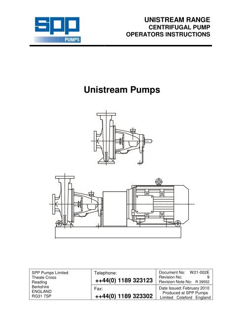
UNISTREAM RANGE<br />
CENTRIFUGAL PUMP<br />
OPERATORS INSTRUCTIONS<br />
<strong>Unistream</strong> <strong>Pumps</strong><br />
SPP <strong>Pumps</strong> Limited<br />
Theale Cross<br />
Reading<br />
Berkshire<br />
ENGLAND<br />
RG31 7SP<br />
Telephone:<br />
++44(0) 1189 323123<br />
Fax:<br />
++44(0) 1189 323302<br />
Document No: W21-002E<br />
Revision No: 9<br />
Revision Note No: R 39552<br />
Date Issued: February 2010<br />
Produced at SPP <strong>Pumps</strong><br />
Limited Coleford Engl<strong>and</strong>
DECLARATION OF CONFORMITY<br />
We<br />
SPP <strong>Pumps</strong> Limited<br />
Of<br />
Theale Cross<br />
Reading<br />
Berkshire<br />
Engl<strong>and</strong><br />
RG31 7SP<br />
Declare that:<br />
Equipment:<br />
Model/Type:<br />
Serial Number:<br />
CENTRIFUGAL PUMP<br />
UNISTREAM RANGE<br />
As shown on the Pump Nameplate<br />
For pumps <strong>and</strong> pumpsets:<br />
in accordance with the following Directives:<br />
2006/42/EC<br />
The Machinery Directive <strong>and</strong> its amending directives<br />
2006/95/EC<br />
Low Voltage Directive<br />
have been designed <strong>and</strong> manufactured to the following specifications:<br />
EN 809:1998+A1:2009 <strong>Pumps</strong> & Pump Units for Liquids - Safety Requirements<br />
EN 12100:2003<br />
EN 60204-1<br />
Parts 1 <strong>and</strong> 2 - Safety of Machinery<br />
Safety of Machinery - Electrical Equipment<br />
We hereby declare that the equipment named above has been designed to comply with the relevant sections<br />
of the above referenced specifications. The units comply with all essential requirements of the Directive.<br />
For pumps supplied without drivers:<br />
We hereby declare that this equipment is intended to be incorporated into, or assembled with other machinery<br />
to constitute relevant machinery to comply with the essential health <strong>and</strong> safety requirements of the Directive.<br />
The machinery covered by this declaration must NOT be put into service until the relevant machinery into which<br />
it is to be incorporated has been declared in conformity with the provisions of the Directive.<br />
Signed:<br />
Name: John Hollins<br />
Position: Engineering Manager - Authorised to sign on behalf of SPP <strong>Pumps</strong> Limited<br />
Mushet Industrial Park, Coleford, Gloucestershire, Engl<strong>and</strong>, GL16 8PS<br />
Date: 25 February 2010<br />
W21-002E<br />
Our policy is one of continuous improvement <strong>and</strong> we reserve the right to alter specifications at any time<br />
Page 2 of 24
Operators Instructions for<br />
<strong>Unistream</strong> Centrifugal <strong>Pumps</strong><br />
Manual No/Rev<br />
W21-002E / 8<br />
CONTENTS<br />
Section........................................................Page<br />
1 General Information & Safety<br />
Instructions ............................................ 3<br />
2 Transport H<strong>and</strong>ling <strong>and</strong> Storage ........... 4<br />
3 General Description............................... 5<br />
4 Assembly <strong>and</strong> Installation...................... 5<br />
5 Commissioning <strong>and</strong> Operation .............. 7<br />
6 Maintenance <strong>and</strong> Service ...................... 9<br />
7 Faults <strong>and</strong> Remedial Action................. 14<br />
8 Pump Details: ...................................... 14<br />
8.1 Pump Dimensions & Weights ........... 15<br />
8.2 Pump Sections <strong>and</strong> Parts Lists......... 15<br />
8.3 Pump Connections ........................... 20<br />
9 Additional Information.......................... 22<br />
10 Bolt Torque Recommendations........... 23<br />
11 Spares <strong>and</strong> Service ............................. 24<br />
Manufacturers Information:<br />
(Where applicable)<br />
Seal & Seal System .......................... Appendix I<br />
Coupling .......................................... Appendix II<br />
Electric Motor.................................. Appendix III<br />
Introduction<br />
This manual gives the safety, installation, operation<br />
<strong>and</strong> maintenance instructions for pumps in the SPP<br />
<strong>Pumps</strong> UNISTREAM range of horizontal, end<br />
suction, centrifugal pumps for general <strong>and</strong><br />
industrial use<br />
<strong>Pumps</strong> may be identified by the SPP <strong>Pumps</strong> code<br />
typically in the form 'KP04E' or by the Equivalent<br />
St<strong>and</strong>ard pump code typically in the form '40/26'.<br />
This manual applies to the following pump types:<br />
SIZE<br />
Code<br />
Pump Size Code<br />
Delivery<br />
Branch<br />
Dia.<br />
mm.<br />
St<strong>and</strong>ard<br />
Size<br />
Code<br />
TYPE<br />
Suffix<br />
Type Suffix Letter<br />
Nominal<br />
Impeller<br />
Dia.<br />
mm.<br />
St<strong>and</strong>ard<br />
Size<br />
Suffix<br />
KP03 32 32/** B 125 **/13<br />
KP04 40 40/** C 160 **/16<br />
KP05 50 50/** D 200 **/20<br />
KP06 65 65/** E 250 **/26<br />
KP08 80 80/** F 315 **/32<br />
KP10 100 100/** G 400 **/40<br />
KP12 125 125/** V X Y These pumps are.<br />
KP15 150 150/** & Z non-st<strong>and</strong>ard<br />
Use this table to convert the pump type code into<br />
the equivalent st<strong>and</strong>ard code to obtain information<br />
for your pump from the manual. Note, for pump<br />
types AV03N, KP08V & Y, KP10X & Y, KP12X & Z,<br />
& KP15Y, please refer to separate manuals W21-<br />
003E <strong>and</strong> W21-004E<br />
1. General Information <strong>and</strong> Safety<br />
Instructions<br />
The products supplied by SPP <strong>Pumps</strong> Ltd. have<br />
been designed with safety in mind. Where hazards<br />
cannot be eliminated, the risk has been minimised<br />
by the use of guards <strong>and</strong> other design features.<br />
Some hazards cannot be guarded against <strong>and</strong> the<br />
instructions below MUST BE COMPLIED WITH for<br />
safe operation. These instructions cannot cover all<br />
circumstances; YOU are responsible for using safe<br />
working practices at all times.<br />
1.1 SPP <strong>Pumps</strong> Ltd. products are designed for<br />
installation in designated areas, which are to<br />
be kept clean <strong>and</strong> free of obstructions that<br />
may restrict safe access to the controls <strong>and</strong><br />
maintenance access points.<br />
A pump nameplate is fitted to each unit <strong>and</strong><br />
must not be removed. Loss of this plate<br />
could make identification impossible. This<br />
in turn could affect safety <strong>and</strong> cause difficulty<br />
in obtaining spare parts. Should accidental<br />
loss or damage occur, contact SPP <strong>Pumps</strong><br />
Ltd. immediately.<br />
1.2 Access to the equipment should be<br />
restricted to the personnel responsible for<br />
installation, operation <strong>and</strong> maintenance <strong>and</strong><br />
they must be trained, adequately qualified<br />
<strong>and</strong> supplied with the appropriate tools for<br />
their respective tasks.<br />
1.3 SPP <strong>Pumps</strong> Ltd. requires that all personnel<br />
that are responsible for installation, operation<br />
or maintenance of the equipment, have<br />
access to <strong>and</strong> study the product instruction<br />
manual BEFORE any work is done <strong>and</strong> that<br />
they will comply with all local <strong>and</strong> industry<br />
based safety instructions <strong>and</strong> regulations.<br />
1.4 Ear defenders should be worn where the<br />
specified equipment noise level exceeds<br />
locally defined safe levels. Safety glasses or<br />
goggles should be worn where working with<br />
pressurised systems <strong>and</strong> hazardous<br />
substances. Other personal protection<br />
equipment must be worn where local rules<br />
apply.<br />
1.5 Do NOT wear loose or frayed clothing or<br />
jewellery that could catch on the controls or<br />
become trapped in the equipment.<br />
1.6 Check <strong>and</strong> confirm that the manual is the<br />
relevant copy by comparing the serial<br />
number on the identification plate with that<br />
on the manual.<br />
Our policy is one of continuous improvement <strong>and</strong> we reserve the right to alter specifications at any time<br />
Page 3 of 24
Manual No/Rev<br />
W21-002E / 8<br />
Operators Instructions for<br />
<strong>Unistream</strong> Centrifugal <strong>Pumps</strong><br />
1.7 Note any limits to the pump application<br />
specified in the contract documentation.<br />
Operation of the equipment outside these<br />
limits will increase the risk from hazards<br />
noted below <strong>and</strong> may lead to premature <strong>and</strong><br />
hazardous pump failure.<br />
<strong>Pumps</strong> supplied on<br />
pallets may be lifted<br />
by forklift truck, to lift<br />
from the pallet the<br />
pump should be<br />
slung as shown.<br />
Sling<br />
1.8 Clear <strong>and</strong> easy access to all controls,<br />
gauges <strong>and</strong> dials etc. MUST be maintained<br />
at all times. Hazardous or flammable<br />
materials must NOT be stored in pump<br />
rooms unless safe areas or racking <strong>and</strong><br />
suitable containers have been provided.<br />
1.9 IMPROPER INSTALLATION, OPERATION<br />
OR MAINTENANCE OF THIS SPP PUMPS<br />
LTD PRODUCT COULD RESULT IN<br />
INJURY OR DEATH.<br />
1.10 Within the manual, safety instructions are<br />
marked with safety symbols.<br />
Pump weight is<br />
shown on the<br />
General Arrangement<br />
drawing.<br />
<strong>Pumps</strong>ets fitted with lifting eyebolts must be<br />
lifted using suitable four chain lifting<br />
equipment thus<br />
Sling here for lifting<br />
complete pumpset<br />
Eyebolt for<br />
lifting motor<br />
alone<br />
Hazard<br />
Hazard<br />
This symbol refers to general<br />
mechanical aspects of safety.<br />
This symbol refers to electrical<br />
safety.<br />
This symbol gives<br />
ATTENTION<br />
warning of a hazard to the<br />
pump itself, which in turn, could cause a risk<br />
to personal safety.<br />
2.3 Storage<br />
2.3.1 Temporary Storage for up to Six Weeks<br />
2. Transport H<strong>and</strong>ling <strong>and</strong><br />
Storage Instructions<br />
2.1 Transport<br />
<strong>Unistream</strong> pumps are despatched fully<br />
assembled but for overseas orders the<br />
lubricating oil in the bearing housing is<br />
drained. <strong>Pumps</strong> are protected against<br />
corrosion <strong>and</strong> packed for transport by normal<br />
road, rail <strong>and</strong> sea carriers.<br />
2.2 H<strong>and</strong>ling<br />
Crushing Hazard<br />
When lifting the pump unit, use<br />
lifting equipment having a safe<br />
working load rating suitable for the weight<br />
specified. Use suitable slings for lifting any<br />
pump not provided with lifting points.<br />
The use of suitable forklift truck <strong>and</strong> fourchain<br />
crane sling equipment is<br />
recommended but locally approved<br />
equipment of suitable rating maybe used.<br />
If the pump unit is not to be used<br />
immediately it should be stored carefully in a<br />
horizontal position, in a sheltered, dry<br />
location. Additional rust preventative should<br />
be applied to all unpainted carbon steel or<br />
cast iron parts, <strong>and</strong> should not be removed<br />
until final installation.<br />
2.3.2 Long Term Storage<br />
Shearing Hazard<br />
DO NOT place fingers or h<strong>and</strong>s etc.<br />
into the suction or discharge pipe<br />
outlets <strong>and</strong> do NOT touch the impeller, if<br />
rotated this may cause severe injury.<br />
To prevent ingress of any objects, retain the<br />
protection covers or packaging in place until<br />
removal is necessary for installation. If the<br />
packaging or suction <strong>and</strong> discharge covers<br />
are removed for inspection purposes,<br />
replace afterwards to protect the pump <strong>and</strong><br />
maintain safety.<br />
Fill the bearing housing with recommended<br />
oil to ensure that the shaft <strong>and</strong> bearings<br />
remain rust free. Remove the gl<strong>and</strong>,<br />
packing rings <strong>and</strong> lantern ring, cover metallic<br />
parts with rust preventative <strong>and</strong> wrap all<br />
Our policy is one of continuous improvement <strong>and</strong> we reserve the right to alter specifications at any time<br />
Page 4 of 24
Operators Instructions for<br />
<strong>Unistream</strong> Centrifugal <strong>Pumps</strong><br />
Manual No/Rev<br />
W21-002E / 8<br />
parts for storage with the pump.<br />
The pump shaft should be rotated by h<strong>and</strong> at<br />
least five turns every six weeks. For special<br />
protection of the coupling <strong>and</strong> electric motor,<br />
where applicable, refer to the manufacturers'<br />
instructions in the relevant appendix.<br />
2.3.3 Exposed or Extreme Conditions Storage<br />
For exposed storage or extreme variants in<br />
atmospheric or environmental conditions,<br />
please refer to SPP <strong>Pumps</strong> Ltd. for special<br />
storage instructions to suit the conditions<br />
applicable.<br />
3. General Description<br />
SPP <strong>Pumps</strong> Ltd. <strong>Unistream</strong> <strong>Pumps</strong> are a<br />
range of horizontal centrifugal pumps that<br />
comply with Pump St<strong>and</strong>ard DIN24255. The<br />
materials of construction can be either all<br />
iron or iron with bronze fittings.<br />
3.1 <strong>Pumps</strong><br />
The mechanical assembly comprises a rigid<br />
shaft, supported by oil-lubricated bearings<br />
with a double shrouded type impeller<br />
mounted in a removable bearing housing<br />
assembly. This is attached to an end suction<br />
volute casing fitted with wear ring(s). The<br />
bearing housing, shaft <strong>and</strong> impeller<br />
assembly can be withdrawn from the volute<br />
for maintenance without disconnection of<br />
pipework.<br />
The discharge branch is positioned vertically<br />
opposite the main pump mounting feet, an<br />
additional mounting foot is fitted at the outer<br />
bearing position for stability.<br />
The complete assembly is of a rigid<br />
construction, being intended for mounting on<br />
suitable baseplate with electric or other<br />
motor driver. A suitable coupling is required<br />
to transmit the rotational drive between<br />
pump <strong>and</strong> motor. A spacer coupling can be<br />
fitted to allow the removal of the pump<br />
rotating assembly without disconnecting<br />
pipework <strong>and</strong> removal of the motor.<br />
The shaft is sealed with a soft packed gl<strong>and</strong><br />
for fire pump applications.<br />
the pump only.<br />
(2) Suction pressure must be included when<br />
assessing the Maximum Working Pressure.<br />
3.2 Long Coupled <strong>Pumps</strong>ets<br />
These pumpsets are supplied with<br />
baseplate, coupling <strong>and</strong> electric motors,<br />
specified to meet the pump duty <strong>and</strong><br />
customer requirements. Baseplates are<br />
usually of the SPP <strong>Pumps</strong> Ltd. steel plate<br />
design but fabricated baseplates may be<br />
supplied to meet additional requirements.<br />
A proprietary flexible coupling is fitted, this<br />
has been selected to meet the power<br />
transmission <strong>and</strong> other operating<br />
requirements for the pumpset. Coupling<br />
details are given in the manufacturers<br />
instructions in Appendix II.<br />
For details of the motor supplied, refer to the<br />
manufacturer's instructions in Appendix III.<br />
4. Assembly <strong>and</strong> Installation<br />
Shearing Hazard<br />
Do NOT place fingers or h<strong>and</strong>s etc.<br />
into the suction or discharge pipe<br />
outlets <strong>and</strong> do NOT touch the impeller, if<br />
rotated this may cause severe injury. To<br />
prevent ingress of any objects, retain the<br />
protection covers or packaging in place until<br />
removal is necessary for installation.<br />
4.1 Initial Inspection for Damage<br />
During transport <strong>and</strong> storage, accidental<br />
damage to the pump may have occurred.<br />
When the pump is to be installed, or in the<br />
event of a h<strong>and</strong>ling accident, carefully<br />
check that no damage has been sustained<br />
by the pump before installation <strong>and</strong><br />
commissioning.<br />
4.2 Preparation for Mounting<br />
Before installation, check that the pump<br />
mounting location is suitable for accepting<br />
the pump unit. Refer to Section 8, for details<br />
of pump installation dimensions or to a<br />
certified General Arrangement Drawing<br />
when available.<br />
Nameplate details are shown on the back<br />
cover, full pump specification can be<br />
supplied on a data sheet, if requested.<br />
Note (1) Head specified is the Duty Head generated by<br />
Our policy is one of continuous improvement <strong>and</strong> we reserve the right to alter specifications at any time<br />
Page 5 of 24
Manual No/Rev<br />
W21-002E / 8<br />
4.3 Pump Preparation<br />
Operators Instructions for<br />
<strong>Unistream</strong> Centrifugal <strong>Pumps</strong><br />
c) Confirm Lateral Alignment<br />
Abrasion <strong>and</strong> Entrapment<br />
Hazard<br />
Do NOT touch any moving or<br />
rotating parts. Guards are provided to<br />
prevent access to these parts, where they<br />
have been removed for maintenance they<br />
MUST be replaced before operating the<br />
equipment.<br />
Remove packaging but leave the flange<br />
covers in place, check that impeller rotates<br />
freely by h<strong>and</strong> by turning the shaft.<br />
4.4 Pump Installation<br />
It is recommended that the pump unit is<br />
fitted to the baseplate before fitting the motor<br />
<strong>and</strong> coupling. The distance between shaft<br />
ends should be established to suit the<br />
coupling by reference to the manufacturer's<br />
instructions.<br />
4.5 Shaft Alignment<br />
To minimise the side load on the bearings<br />
<strong>and</strong> to achieve full coupling <strong>and</strong> bearing life.<br />
It is recommended that the shafts are<br />
aligned as accurately as possible i.e. well<br />
below the allowable misalignment of the<br />
coupling.<br />
Refer to the coupling manufacturer's<br />
instructions or proceed generally thus:<br />
a) Lateral Alignment<br />
Mount a dial gauge<br />
on the motor shaft<br />
or coupling with the<br />
gauge running on<br />
the machined<br />
diameter of the<br />
pump coupling. Turn the motor shaft <strong>and</strong><br />
note the total indicator reading.<br />
b) Angular Alignment<br />
Mount a dial gauge<br />
on the motor shaft<br />
or coupling to run<br />
on a face of the<br />
pump coupling as<br />
near the outside<br />
diameter as<br />
possible. Turn the motor shaft <strong>and</strong> note<br />
the total indicator reading.<br />
Mount the dial<br />
gauge on the pump<br />
shaft or coupling<br />
with the gauge<br />
running on the<br />
machined diameter<br />
of the motor<br />
coupling. Turn the pump shaft <strong>and</strong> note the<br />
total indicator reading.<br />
d) Adjustment<br />
The motor must be shimmed <strong>and</strong> repositioned<br />
to align the shafts within the<br />
coupling manufacturer's specifications.<br />
e) Alternative Method<br />
If a dial gauge is not available, callipers or<br />
taper gauge may be used to measure the<br />
distance between the coupling flanges at<br />
four points around the circumference <strong>and</strong> a<br />
straight edge used to check the lateral<br />
alignment of the outer flange diameters.<br />
Shaft alignment must be<br />
ATTENTION<br />
checked again after the<br />
final positioning of the pump unit <strong>and</strong><br />
connection to pipework as this may have<br />
disturbed the pump or motor mounting<br />
positions.<br />
ATTENTION<br />
If hot liquids (above<br />
80°C) are being<br />
pumped, alignment should be checked <strong>and</strong><br />
reset with the pump <strong>and</strong> motor at their<br />
normal operating temperature. If this is not<br />
possible, SPP <strong>Pumps</strong> Ltd. can supply<br />
estimated initial offset figures to suit<br />
extreme operating temperatures.<br />
4.6 Suction Pipework<br />
The run of suction pipework must be such<br />
that air can NOT become trapped where it<br />
would be sucked into the pump on starting.<br />
The bore of suction pipe is recommended<br />
to be one or two sizes larger than the pump<br />
suction branch <strong>and</strong> reducers if used must<br />
be eccentric to eliminate the possibility of<br />
an air pocket being formed.<br />
Bends in the suction pipeline should be as<br />
large as possible, the pipe made as short<br />
<strong>and</strong> as straight as possible <strong>and</strong> all joints<br />
must be fully airtight. If fitting a foot valve, it<br />
should have a free area of one <strong>and</strong> a half<br />
times the area of the suction pipe.<br />
Our policy is one of continuous improvement <strong>and</strong> we reserve the right to alter specifications at any time<br />
Page 6 of 24
Operators Instructions for<br />
<strong>Unistream</strong> Centrifugal <strong>Pumps</strong><br />
Manual No/Rev<br />
W21-002E / 8<br />
Unacceptable Suction Pipework<br />
Trapped Air<br />
Preferred Pipework<br />
Discharge Pipe<br />
Discharge<br />
Valve<br />
Unsupported Pipe<br />
Suction Valve<br />
Check Valve<br />
Increaser<br />
Eccentric<br />
Reducer<br />
UNISUC02.CDR<br />
Where pumping water at temperatures<br />
above 70°C, care must be taken to ensure<br />
that enough pressure is available at the<br />
impeller entry to prevent vaporisation.<br />
Suction Pipe<br />
UNIPIP02.CDR<br />
An appropriate fine strainer is recommended<br />
to prevent foreign matter from being drawn<br />
into the pump. A screen or basket strainer<br />
may also be required to hold back larger<br />
items. These should be sized to maintain the<br />
flow through them to below 0.6 m/s.<br />
The suction pipe work must be flushed clean<br />
to ensure that site debris is not drawn into<br />
the pump when it is commissioned.<br />
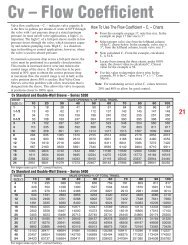
4.7 Discharge Pipework<br />
The bore of the discharge pipe should be<br />
sized to ensure a flow velocity of 2.5 to 3 m/s<br />
is not exceeded. This is usually one size<br />
larger than the discharge branch. Pipework<br />
should be as short <strong>and</strong> straight as possible<br />
to reduce friction head loss.<br />
A non-return valve is usually fitted to prevent<br />
the pump from excessive back pressure <strong>and</strong><br />
reverse rotation <strong>and</strong> a discharge valve is<br />
usually fitted to regulate the flow <strong>and</strong> allow<br />
for inspection <strong>and</strong> maintenance on the<br />
pump.<br />
The suction <strong>and</strong> discharge pipework must be<br />
independently supported <strong>and</strong> positioned<br />
such that no excessive forces <strong>and</strong> moments<br />
are exerted on the pump flanges.<br />
Failure to support suction<br />
ATTENTION<br />
<strong>and</strong> delivery pipework<br />
may result in distortion of the pump casing,<br />
with the possibility of early pump failure.<br />
4.8 Foundations<br />
The baseplate must be secured to<br />
substantial foundations with suitable<br />
foundation bolts to minimise vibrations. A<br />
space of approximately 25mm should be left<br />
between the baseplate <strong>and</strong> the foundations<br />
for grouting. After the grouting has dried, the<br />
foundation bolts should be tightened <strong>and</strong> the<br />
shaft alignment checked again before<br />
commissioning <strong>and</strong> putting the pump into<br />
operation.<br />
5. Commissioning <strong>and</strong> Operation<br />
5.1 Commissioning Checks<br />
These checks must be done after first<br />
installation <strong>and</strong> after pump maintenance that<br />
requires removal of the rotating assembly.<br />
Abrasion <strong>and</strong> Entrapment Hazard<br />
Do NOT touch any moving or<br />
rotating parts. Guards are provided<br />
to prevent access to these parts, where they<br />
have been removed for maintenance they<br />
MUST be replaced before operating the<br />
equipment.<br />
If the gl<strong>and</strong> packing has been removed for<br />
storage, this must be replaced as described<br />
in Section 6.2.3 - Re-packing.<br />
Check the level of the oil in the bearing<br />
housing is at the level mark on the sight<br />
glass on the side of the bearing housing.<br />
Refer to Section 6.4 - Bearing Lubrication.<br />
If the shaft sealing is by gl<strong>and</strong> packing, the<br />
packing should be relatively slack <strong>and</strong> check<br />
that the gl<strong>and</strong> (45.2) is free.<br />
Our policy is one of continuous improvement <strong>and</strong> we reserve the right to alter specifications at any time<br />
Page 7 of 24
Manual No/Rev<br />
W21-002E / 8<br />
Operators Instructions for<br />
<strong>Unistream</strong> Centrifugal <strong>Pumps</strong><br />
If the stuffing box is supplied with cooling<br />
water or the mechanical seal is supplied with<br />
clean water flush, check that the water<br />
supply is turned on.<br />
Failure to supply the<br />
ATTENTION<br />
stuffing box or mechanical<br />
seal with cooling or flush water may result in<br />
damage <strong>and</strong> premature failure of the pump.<br />
Check that the rotating assembly is free to<br />
rotate by h<strong>and</strong> before connecting the power<br />
supply. Also check that the piping system<br />
has been properly connected with all joints<br />
tightened <strong>and</strong> instrumentation is in position.<br />
Check that the pump is<br />
ATTENTION<br />
primed. <strong>Pumps</strong> should<br />
never be run dry as the pumped liquid acts<br />
as a lubricant for the close running fits<br />
surrounding the impeller <strong>and</strong> damage will be<br />
incurred.<br />
Prime the pump using an ejector, exhauster<br />
or vacuum pump. If a foot valve is used in<br />
the suction line the pump may be primed by<br />
venting <strong>and</strong> filling the casing with liquid.<br />
Connect the electrical supply to the pump<br />
unit. Momentarily switch on motor <strong>and</strong> check<br />
direction of rotation. This should be such that<br />
the pump assembly turns clockwise when<br />
viewed on the driven end. For three phase<br />
electric motors, if direction of rotation is<br />
incorrect, disconnect the supply <strong>and</strong> change<br />
over two of three supply wires.<br />
After the first 200 hours running from new,<br />
change the bearing lubricating oil. Refer to<br />
Section 6.4 - Bearing Lubrication.<br />
5.1 Starting Procedure<br />
BEFORE A UNISTREAM PUMP IS STARTED<br />
ALWAYS ENSURE THAT THE SUMP IS FILLED<br />
TO THE CORRECT LEVEL WITH LIQUID, AND<br />
THAT ANY LEVEL CONTROLS ARE<br />
FUNCTIONING CORRECTLY.<br />
Abrasion <strong>and</strong> Entrapment Hazard<br />
Do NOT touch any moving or<br />
rotating parts. Guards are provided<br />
to prevent access to these parts, where they<br />
have been removed for maintenance they<br />
MUST be replaced before operating the<br />
equipment.<br />
Before starting, check the level of oil in the<br />
bearing housing is at the level mark on the<br />
sight glass on the side of the bearing<br />
housing. Refer to Section 6.4 - Bearing<br />
Lubrication.<br />
Check that the suction valve is open <strong>and</strong> that<br />
the pump is primed.<br />
Open the discharge valve to one quarter<br />
open to prevent hydraulic lock from<br />
occurring. Switch on the motor <strong>and</strong> allow it to<br />
build up to full operating speed. Slowly open<br />
discharge valve until the pump reaches the<br />
required duty condition.<br />
Check that the motor is not overloading, unit<br />
is not vibrating or excessively noisy, bearings<br />
or gl<strong>and</strong> packing are not overheating, <strong>and</strong><br />
that the pump is developing the correct flow<br />
<strong>and</strong> head requirements.<br />
If the pump is operating at its normal speed,<br />
the pump should be shut down at once if any<br />
of the following defects are found:<br />
a) No liquid delivered.<br />
b) Not enough liquid delivered.<br />
c) Not enough pressure.<br />
d) Loss of liquid after starting.<br />
e) Vibration.<br />
f) Motor runs hot.<br />
g) Excessive noise from cavitation.<br />
h) Pump overheating.<br />
Recommended corrective action for these<br />
faults is given in Section 7 Faults <strong>and</strong><br />
Remedial Action.<br />
5.2 During Operation<br />
Hot Surfaces Hazard<br />
Do NOT touch surfaces that<br />
during normal running will be sufficiently hot<br />
to cause injury. These are marked with the<br />
HOT warning symbol. Note that these<br />
surfaces will remain hot after the pump<br />
has stopped, allow sufficient time for<br />
cooling before maintenance. Be cautious<br />
<strong>and</strong> note that other parts of the pump may<br />
become hot if a fault is<br />
developing.<br />
Cold Conditions Hazard<br />
Do NOT operate water pumps in<br />
temperatures below freezing point, without<br />
first checking that the pumped fluid is not<br />
frozen <strong>and</strong> the pump is free to turn. <strong>Pumps</strong><br />
in these environments should be drained<br />
down during inactivity <strong>and</strong> re-primed before<br />
starting.<br />
Hazardous Noise<br />
In addition to local or site<br />
regulations for noise protection, SPP <strong>Pumps</strong><br />
Ltd recommend the use of Personal Ear<br />
Protection equipment in all enclosed pump<br />
rooms <strong>and</strong> particularly those containing<br />
diesel engines. Care must be taken to<br />
ensure that any audible alarm or warning<br />
Our policy is one of continuous improvement <strong>and</strong> we reserve the right to alter specifications at any time<br />
Page 8 of 24
Operators Instructions for<br />
<strong>Unistream</strong> Centrifugal <strong>Pumps</strong><br />
Manual No/Rev<br />
W21-002E / 8<br />
signal can still be heard with ear defenders<br />
worn.<br />
Hazardous Gases, Mists, Sprays<br />
<strong>and</strong> Leaks<br />
Be aware of the hazards relating to<br />
the pumped fluid, especially the danger from<br />
inhalation of noxious <strong>and</strong> toxic gases, skin<br />
<strong>and</strong> eye contact or penetration. Obtain <strong>and</strong><br />
underst<strong>and</strong> the hazardous substance<br />
(COSHH) data sheets relating to the<br />
pumped fluid <strong>and</strong> note the recommended<br />
emergency <strong>and</strong> first aid procedures.<br />
Periodic Checks:<br />
a) Stuffing Box:<br />
Check that there is sufficient leakage to<br />
lubricate <strong>and</strong> cool the packing, between 30<br />
<strong>and</strong> 120 drops per minute is required. Check<br />
also that the drain pipes are clear of<br />
obstruction.<br />
b) Bearings:<br />
Check the bearing temperatures do not<br />
exceed 70°C as an increase may indicate<br />
the early stages of bearing trouble.<br />
c) Noise:<br />
Listen for any unusual noise or an increase<br />
in normal sound level.<br />
This may result from:<br />
i) Loose fasteners for guards <strong>and</strong> other<br />
equipment.<br />
ii)<br />
iii)<br />
Worn coupling.<br />
Air trapped in the pump i.e. the pump<br />
was not fully primed.<br />
iv) Cavitation caused by air in the liquid<br />
from leaks in the suction pipework.<br />
v) Small solids in the liquid.<br />
NOTE - At certain installations or at certain<br />
operation points on the pump curve, the<br />
noise level 70dB (or the actual pump<br />
specified noise level) can be exceeded.<br />
d) Alignment:<br />
Alignment should be checked after the first<br />
run <strong>and</strong> after any maintenance requiring<br />
removal or disconnection of the coupling.<br />
For detailed instructions, refer to Section 4.5<br />
- Shaft Alignment<br />
e) Suction Gauge Reading:<br />
If this is higher than normal, investigate <strong>and</strong><br />
check that valves in the suction pipework are<br />
fully open or that the suction lift may have<br />
increased.<br />
f) Discharge Gauge Reading:<br />
If this is lower than normal, check for a leak<br />
in the associated pipework or that a valve in<br />
the delivery line has been opened when<br />
normally it is partially closed.<br />
5.3 Stopping Procedure<br />
Stop the motor then fully close the discharge<br />
valve.<br />
6. Maintenance <strong>and</strong> Service<br />
6.1 General Introduction<br />
SPP <strong>Pumps</strong> Ltd <strong>Unistream</strong> pumps will<br />
provide many years of trouble free service<br />
when maintained in accordance with these<br />
instructions. In the event of failure of the<br />
pump it is recommended that SPP <strong>Pumps</strong><br />
Ltd. Service Department is called to<br />
investigate <strong>and</strong> carry out repairs. The<br />
following instructions are given to cover the<br />
main elements of strip <strong>and</strong> rebuild but do<br />
NOT include instructions for work that MUST<br />
be done by an SPP <strong>Pumps</strong> Ltd. Service<br />
Engineer.<br />
Recommended Maintenance Schedule<br />
Period:<br />
Weekly<br />
After First<br />
200 Hours<br />
Running<br />
Half Yearly<br />
or After<br />
5000<br />
Hours<br />
Running<br />
Maintenance Required:<br />
Carry out periodic checks as shown in<br />
Section 5.3 <strong>and</strong> take corrective action<br />
as shown in Section 7.<br />
Replace the Lubricating Oil as shown in<br />
Section 6.4.<br />
Replace the Lubricating Oil as shown in<br />
Section 6.4.<br />
Check the alignment of pump <strong>and</strong> motor<br />
<strong>and</strong> adjust, as shown in Section 4.5.<br />
Check <strong>and</strong> tighten all holding down bolts<br />
if found loose, refer to Section 9 for<br />
recommended bolt tightening torques.<br />
For soft packed pumps, check the gl<strong>and</strong><br />
adjustment remaining <strong>and</strong> replace<br />
packing if necessary. At the same time,<br />
check the sleeve for scoring <strong>and</strong> replace<br />
if necessary.<br />
Check the coupling for wear as per<br />
manufacturers instructions.<br />
Each Year Assess the performance of the pump<br />
against the duty specifications <strong>and</strong> take<br />
corrective action as shown in Section 7<br />
The following hazards may arise during<br />
maintenance work:<br />
Fluid Pressure Jet Hazards<br />
Check <strong>and</strong> ensure that the pump<br />
operates at below the Maximum<br />
Working Pressure specified in the manual or<br />
on the pump nameplate <strong>and</strong> before<br />
maintenance, ensure that the pump is<br />
Our policy is one of continuous improvement <strong>and</strong> we reserve the right to alter specifications at any time<br />
Page 9 of 24
Manual No/Rev<br />
W21-002E / 8<br />
Operators Instructions for<br />
<strong>Unistream</strong> Centrifugal <strong>Pumps</strong><br />
drained down.<br />
Hazardous Materials<br />
Wear a suitable mask or respirator<br />
when working with Packing <strong>and</strong><br />
Gasket components that contain<br />
fibrous material, as these can be hazardous<br />
when the fibrous dust is inhaled. Be<br />
cautious, if other supplier's components<br />
have been substituted for genuine SPP<br />
<strong>Pumps</strong> Ltd parts, these may then contain<br />
hazardous materials.<br />
Hazardous Gases, Mists, Sprays<br />
<strong>and</strong> Leaks<br />
Be aware of the hazards relating to<br />
the pumped fluid, especially the danger from<br />
inhalation of noxious <strong>and</strong> toxic gases, skin<br />
<strong>and</strong> eye contact or penetration. Obtain <strong>and</strong><br />
underst<strong>and</strong> the hazardous substance<br />
(COSHH) data sheets relating to the<br />
pumped fluid <strong>and</strong> note the recommended<br />
emergency <strong>and</strong> first aid procedures.<br />
BEFORE ATTEMPTING ANY MAINTENANCE ON<br />
A PUMP, PARTICULARLY IF IT HAS BEEN<br />
HANDLING ANY FORM OF HAZARDOUS<br />
LIQUID, ENSURE THAT THE UNIT IS SAFE TO<br />
WORK ON. THE PUMP MUST BE FLUSHED<br />
THOROUGHLY WITH A SUITABLE CLEANSER<br />
TO PURGE AWAY ANY OF THE PRODUCT<br />
LEFT IN THE PUMP COMPONENTS. THIS<br />
SHOULD BE CARRIED OUT BY THE PLANT<br />
OPERATOR AND A CERTIFICATE OF<br />
CLEANLINESS OBTAINED BEFORE STARTING<br />
WORK. TO AVOID ANY RISK TO HEALTH IT IS<br />
ALSO ADVISABLE TO WEAR PROTECTIVE<br />
CLOTHING AS RECOMMENDED BY THE SITE<br />
SAFETY OFFICER, ESPECIALLY WHEN<br />
REMOVING OLD PACKING THAT MAY BE<br />
CONTAMINATED.<br />
6.2 Preparation for Maintenance<br />
Electric Shock & Accidental<br />
Starting Hazard<br />
ISOLATE the equipment before<br />
any maintenance work is done.<br />
Switch off the mains supply, remove fuses,<br />
apply lockouts where applicable <strong>and</strong> affix<br />
suitable isolation warning signs to prevent<br />
inadvertent re-connection.<br />
In order to avoid the possibility of<br />
maintenance personnel inhaling dangerous<br />
fumes or vapours. It is recommended that<br />
maintenance work be carried out away from<br />
the pump location by removal of the bearing<br />
housing <strong>and</strong> shaft assembly to a suitable<br />
maintenance area.<br />
No special tools are required for dismantling<br />
<strong>and</strong> re-assembling, however, it is important<br />
to ensure the suitable lifting equipment is<br />
available <strong>and</strong> that the work is carried out in a<br />
clean area.<br />
6.3 Re-packing the Stuffing Box<br />
Where a soft packed gl<strong>and</strong> is fitted, it will be<br />
necessary to replace the packing periodically<br />
when the gl<strong>and</strong> can no longer be tightened<br />
to reduce leakage to the normal level, or if<br />
the gl<strong>and</strong> suffers from overheating.<br />
6.3.1 Removal <strong>and</strong> Preparation<br />
Close the suction & discharge valves <strong>and</strong><br />
release pressure from the casing.<br />
Remove the gl<strong>and</strong> (45.2), use an extractor<br />
tool to remove packing rings <strong>and</strong> remove the<br />
lantern ring without damaging the sleeve or<br />
stuffing box bore.<br />
PACKING REMOVAL TOOL<br />
PACKREM1.CDR<br />
Clean the sleeve <strong>and</strong> bore of the stuffing box<br />
with a clean oily cloth, also clean the lantern<br />
ring.<br />
6.3.2 Packing Preparation<br />
Packing Ring Dimensions (mm)<br />
Pump Size<br />
32/13<br />
32/16<br />
32/20<br />
32/26<br />
65/26<br />
65/32<br />
40/13<br />
40/16<br />
40/20<br />
40/26<br />
80/20<br />
80/26<br />
80/32<br />
100/40 125/32<br />
125/40<br />
50/13<br />
50/16<br />
50/20<br />
50/26<br />
100/20<br />
100/261<br />
00/32<br />
150/32<br />
15040<br />
65/13<br />
65/16<br />
65/20<br />
Shaft<br />
Unit<br />
80/16 25<br />
125/26 35<br />
Packing Ring Dimensions (mm)<br />
Shaft Unit 25 35 45<br />
Sleeve Dia. (Minus 0.1mm) 32 40 55<br />
Box Dia. (Plus 0.1mm) 48 60 75<br />
Length of Box 50 63 63<br />
Cross Section of Packing 8 x 8 10 x 10 10 x 10<br />
Length per Ring 125 156 203<br />
Number Required with 4 4 4<br />
45<br />
Our policy is one of continuous improvement <strong>and</strong> we reserve the right to alter specifications at any time<br />
Page 10 of 24
Operators Instructions for<br />
<strong>Unistream</strong> Centrifugal <strong>Pumps</strong><br />
Manual No/Rev<br />
W21-002E / 8<br />
<strong>and</strong> without Lantern Ring 6 6 6<br />
If the packing rings are to be cut from a coil,<br />
or length of packing, the size, number of<br />
rings <strong>and</strong> length are shown in the tables.<br />
Wrap the packing strip around a dummy<br />
shaft of the required diameter, overlapping<br />
the coils as shown. Cut diagonally at 45° to<br />
produce rings with an overlapped split joint.<br />
Note that if packing is cut from flat material<br />
or with square joint lines, a good seal will not<br />
be achieved.<br />
6.4 Bearing Lubrication<br />
It is important to maintain the correct level of<br />
oil in the bearing housing. The level must be<br />
maintained at the mark on the sight glass on<br />
the side of the bearing housing.<br />
Avoid over filling with oil that will cause the<br />
bearings to overheat.<br />
If the bearing temperature is always below<br />
50°C, change the oil once per year. If the<br />
pump bearings reach 80°C or if there is a<br />
risk of oil contamination, change the oil every<br />
6 months or after 5000 hours running.<br />
Oil Capacity of Bearing Housings<br />
Shaft Unit 25 35 45<br />
Capacity in Litres 0.2 0.55 0.9<br />
6.3.3 Re-packing<br />
Insert the first ring <strong>and</strong> gently push it to the<br />
bottom of the stuffing box using a suitable<br />
tool taking care not to score the sleeve or<br />
stuffing box bore.<br />
Install the lantern ring checking that its<br />
position coincides with the lubrication<br />
connection.<br />
Insert the second ring as above but with its<br />
joint advanced by 120° from the first ring's<br />
joint position.<br />
Install the required number of further rings to<br />
complete the packing ensuring that the last<br />
ring fitted does not protrude from the stuffing<br />
box bore.<br />
Refit the gl<strong>and</strong> (45.2) <strong>and</strong> tighten the<br />
retaining nuts finger tight only.<br />
Run the pump for 10 minutes at full pressure<br />
<strong>and</strong> tighten the retaining nuts by 1/6 of a turn<br />
(one flat). Repeat this at ten-minute intervals<br />
until leakage is reduced to a trickle (30 to<br />
120 drops per minute), this being required to<br />
ensure that the gl<strong>and</strong> packing is lubricated.<br />
6.3 Maintenance of Mechanical Seals<br />
Generally there are is no maintenance<br />
required on mechanical seals, but if it is<br />
required, the manufacturer's information is<br />
given in Appendix l.<br />
Recommended Lubricants:<br />
International<br />
St<strong>and</strong>ard /<br />
As Supplied<br />
For continuous bearing<br />
temperatures up to 80°C<br />
Speed up to Speed above<br />
1500 rpm. 1500 rpm.<br />
St<strong>and</strong>ard ISO VG 100 ISO VG 68<br />
TEXACO<br />
RANDO<br />
HD 100<br />
6.5 Disassembly of the Pump<br />
RANDO<br />
HD 68<br />
Refer to Section 8 - Pump Cross-Section<br />
Drawings.<br />
The pump is designed to allow removal of<br />
the bearing housing, shaft <strong>and</strong> impeller<br />
assembly without disconnecting the<br />
pipework. If the pump is fitted with a spacer<br />
coupling, the motor need not be removed.<br />
Remove coupling <strong>and</strong> motor if necessary to<br />
allow withdrawal of the pump assembly.<br />
Remove the bolts connecting the bearing<br />
mounting bracket (18.3) to the baseplate.<br />
If fitted, disconnect the seal lubrication<br />
pipe(s) <strong>and</strong> drain the bearing housing by<br />
removal of the drain plug (90.31).<br />
Unscrew the nuts (92.0) from the volute<br />
casing studs.<br />
Remove the casing cover (16.1) <strong>and</strong> the<br />
bearing housing (33.0) complete with rotor<br />
using screwdrivers or similar tools as levers<br />
in the gap between the volute casing (10.2)<br />
<strong>and</strong> the casing cover (16.1).<br />
Our policy is one of continuous improvement <strong>and</strong> we reserve the right to alter specifications at any time<br />
Page 11 of 24
Manual No/Rev<br />
W21-002E / 8<br />
Operators Instructions for<br />
<strong>Unistream</strong> Centrifugal <strong>Pumps</strong><br />
Undo the impeller nut (92.2) in a counter<br />
clockwise direction <strong>and</strong> withdraw the impeller<br />
(23.0) from the shaft (21.1).<br />
For pumps fitted with a soft packed stuffing<br />
box:<br />
Removal of the packed stuffing box depends<br />
on the pump construction:<br />
a) For pumps with shaft sizes 25, 35 <strong>and</strong> 45<br />
with a bolted casing cover construction only,<br />
remove stud nuts (92.02) from the bearing<br />
housing first, before proceeding with<br />
instruction b).<br />
mechanical seal (43.3), from the bearing<br />
housing (33.0). Care must be taken to<br />
ensure that the stationery element of the<br />
seal <strong>and</strong> the shaft are not damaged when<br />
extracting the shaft.<br />
c) The stationery element of the seal may be<br />
removed from the casing cover by pressing<br />
out by h<strong>and</strong> from the drive end. If the<br />
stationery element is damaged or shows<br />
signs of wear, it must be replaced.<br />
Pull off thrower (50.7) from shaft (21.1).<br />
Unscrew the hexagon screws (90.1) <strong>and</strong><br />
remove both bearing covers (36.0) from the<br />
bearing housing (33.0).<br />
For pumps with shaft size 25 or 35 <strong>and</strong> with<br />
clamped casing cover construction,<br />
commence disassembly with instruction b).<br />
b) Using screwdrivers or similar tools as levers<br />
in the recesses provided, carefully prise<br />
apart <strong>and</strong> remove the casing cover (16.1)<br />
complete with stuffing box packing (46.1),<br />
lantern ring (45.8) <strong>and</strong> gl<strong>and</strong> (45.2), from the<br />
bearing housing (33.0).<br />
c) Dismantle the shaft sleeve (52.4), gl<strong>and</strong><br />
(45.2), stuffing box packing (46.1) <strong>and</strong><br />
lantern ring (45.8).<br />
For pumps fitted with a mechanical seal:<br />
Remove the impeller key (94.01) <strong>and</strong><br />
carefully withdraw the shaft sleeve (52.3)<br />
complete with the rotating element of the<br />
mechanical seal (43.3).<br />
Note: If after examination of the rotating<br />
element, it is found necessary to remove the<br />
rubber bellows from the shaft sleeve, the<br />
complete mechanical seal assembly will<br />
have to be replaced.<br />
Removal of the mechanical seal depends on<br />
the pump construction:<br />
For pumps with shaft sizes 25, 35 <strong>and</strong> 45<br />
with a bolted casing cover construction only.<br />
a) Remove stud nuts (92.02) from the bearing<br />
housing first, before proceeding with<br />
instruction b).<br />
For pumps with shaft size 25 or 35 <strong>and</strong> with<br />
clamped casing cover construction,<br />
commence with instruction b).<br />
b) Using screwdrivers or similar tools as levers<br />
in the recesses provided, carefully prise<br />
apart <strong>and</strong> remove the casing cover (16.1)<br />
complete with the stationery element of the<br />
Using a soft faced hammer or suitable drift,<br />
carefully drive the pump shaft (21.1) out with<br />
its bearings in the direction of the drive end,<br />
i.e. away from the pump end, ensuring that<br />
the impeller nut thread is not damaged.<br />
Care must be taken to ensure that the pump<br />
end bearing passes centrally through the<br />
bore of the drive end bearing housing.<br />
The bearings (32.1) may be cleaned <strong>and</strong><br />
checked without removing them from the<br />
shaft. If they need to be replaced, remove<br />
them by use of a suitable puller or by<br />
applying force to the inner ring using a drift<br />
or punch, taking care to turn the shaft such<br />
that the inner ring is kept square to the shaft<br />
until the bearing is free.<br />
Pump & Drive End Bearing Specifications<br />
Shaft Unit 25 35 45<br />
Bearing<br />
Specification<br />
DIN 625<br />
6305<br />
C3<br />
6307<br />
C3<br />
Our policy is one of continuous improvement <strong>and</strong> we reserve the right to alter specifications at any time<br />
Page 12 of 24<br />
6309<br />
C3<br />
If the bearings (32.1) are to be re-used,<br />
ensure they are thoroughly flushed with<br />
white spirit or similar cleaning fluid, dried <strong>and</strong><br />
protected to prevent any abrasive media<br />
from coming into contact with the races balls<br />
<strong>and</strong> rollers. Bearings should be lightly oiled<br />
<strong>and</strong> wrapped for storage.<br />
Check the shaft (21.1) for straightness by<br />
mounting between centres <strong>and</strong> measuring<br />
the runout with a dial gauge at the coupling,<br />
bearing, sleeve <strong>and</strong> impeller positions. Fit<br />
the stuffing box sleeve <strong>and</strong> check again on<br />
this diameter. The run-out should not exceed<br />
0.08 mm in any of the positions measured.<br />
Wear rings may be measured <strong>and</strong> compared<br />
with the dimensions shown in the table<br />
below. If pump efficiency has reduced the<br />
wear rings may be replaced, contact the<br />
SPP <strong>Pumps</strong> Ltd. Spares <strong>and</strong> Service<br />
Departments for fitting new wear rings.
Operators Instructions for<br />
<strong>Unistream</strong> Centrifugal <strong>Pumps</strong><br />
Manual No/Rev<br />
W21-002E / 8<br />
Dia. 1 = Outside Dia.<br />
of Impeller<br />
Dia. 2 = Inside Dia.<br />
of Impeller<br />
Pump Size:<br />
Tolerances<br />
Suction Side<br />
Drive Side<br />
Dia. 1 Dia. 2 Dia. 1 Dia. 2<br />
-0.1 F8 -0.1 F8<br />
32/13 32/16 69.7 70 - -<br />
32/20 32/26 40/13<br />
40/16 40/20<br />
40/26 50/13 50/16<br />
50/20<br />
50/26 65/13 65/16<br />
65/20 65/26<br />
79.7 80 - -<br />
94.7 95 - -<br />
114.7 115 - -<br />
65/32 129.6 130 124.6 125<br />
80/16 80/20 80/26 129.6 130 - -<br />
80/32 139.6 140 134.6 135<br />
100/20 100/26 159.6 160 - -<br />
100/32 159.6 160 154.6 155<br />
100/40 159.6 160 159.6 160<br />
125/26 179.6 180 - -<br />
125/32 125/40 179.6 180 179.6 180<br />
150/32 150/40 199.6 200 199.6 200<br />
If new proprietary parts such as bearings<br />
<strong>and</strong> lip seals are to be fitted, ensure they are<br />
the correct size, grade <strong>and</strong> quality.<br />
When fitting new bearings they should be<br />
pre-heated in an oil bath to 80 0 C for a short<br />
period of time. This will enable the bearing to<br />
be easily slid on the shaft seating <strong>and</strong> when<br />
cool will give a positive shrink fit. Always<br />
ensure bearings abut correctly against shaft<br />
shoulder.<br />
After the shaft (21.1), pair of gaskets (42.02)<br />
<strong>and</strong> the bearing covers (36.0) have been<br />
fitted to the bearing housing (33.0), the end<br />
float of the rotor should be within the<br />
following dimensions<br />
Rotor End Float.<br />
Shaft Unit 25 35 45<br />
Rotor End<br />
Float<br />
0.1 to<br />
0.75 mm<br />
0.3 to<br />
0.94 mm<br />
0.3 to<br />
0.94 mm<br />
Check the locking washer(93.0) for wear or<br />
damage, replace if necessary.<br />
6.7 Installation of Mechanical Seals<br />
6.6 Re-assembly of the Pump.<br />
The pump unit may be re-assembled in the<br />
reverse manner to disassembling. To ensure<br />
correct <strong>and</strong> trouble free operation, care<br />
should be taken on re-assembly <strong>and</strong> the<br />
following precautions taken:<br />
Cleanliness is important ensure that all<br />
pump components together with the working<br />
areas, are completely free of foreign matter,<br />
dirt <strong>and</strong> dust.<br />
All gasket faces are to be properly cleaned<br />
<strong>and</strong> new gaskets fitted. Gasket <strong>and</strong> other<br />
spares kits are available from SPP <strong>Pumps</strong><br />
Ltd. Spares department, for details refer to<br />
Section 8 - Parts Lists.<br />
It is recommended that only spare parts<br />
manufactured by <strong>and</strong> obtained from SPP<br />
<strong>Pumps</strong> Ltd., are used during maintenance<br />
re-assembly of any <strong>Unistream</strong> range pump.<br />
The company cannot be held responsible for<br />
any failure, which may cause danger to<br />
property or health, arising from the use of<br />
spare parts manufactured <strong>and</strong> supplied by<br />
others, these will also invalidate the pump<br />
warranty.<br />
When ordering spare parts it is essential to<br />
quote the pump serial number from the<br />
identification plate <strong>and</strong> the required part<br />
number(s) as shown in the parts list in<br />
Section 8.<br />
Lubricate the outer surface of the stationery<br />
element of the mechanical seal (43.3) with<br />
soapy water or silicone grease (not oil),<br />
ensure that it is square to its housing in the<br />
casing cover (16.1) <strong>and</strong> push home by h<strong>and</strong>,<br />
taking care not to apply excessive force or to<br />
damage the sealing surface. Check that it<br />
has been seated fully <strong>and</strong> that the sealing<br />
surface is clean <strong>and</strong> undamaged.<br />
Refit the casing cover to the bearing<br />
housing, fit the bolts for the bolted casing<br />
cover, tightening them uniformly <strong>and</strong> in<br />
diagonally opposed pairs sequence.<br />
Position the rotating seal face over the shaft<br />
to butt against the static seal element, taking<br />
care not to damage the sealing surfaces.<br />
Insert the gasket (40.01) into the sleeve <strong>and</strong><br />
ensure that it is properly seated.<br />
Lubricate the inner <strong>and</strong> outer surfaces of the<br />
sleeve lightly with silicone grease, fit the<br />
spring assembly in position <strong>and</strong> mount the<br />
sleeve over the shaft, compress the spring<br />
<strong>and</strong> insert the impeller key to retain the<br />
sleeve in position. Ensure that the rotating<br />
seal face is floating against the spring before<br />
re-fitting the impeller.<br />
For SPP <strong>Pumps</strong> Ltd. Spares <strong>and</strong> Service<br />
Department, telephone 0118 9323123, see<br />
the back cover for further details of SPP<br />
<strong>Pumps</strong> Ltd. After Sales Service.<br />
Our policy is one of continuous improvement <strong>and</strong> we reserve the right to alter specifications at any time<br />
Page 13 of 24
Manual No/Rev<br />
W21-002E / 8<br />
Operators Instructions for<br />
<strong>Unistream</strong> Centrifugal <strong>Pumps</strong><br />
7. Faults <strong>and</strong> Remedial Action<br />
POTENTIAL FAULT OR DEFECT:<br />
No liquid delivered.<br />
<br />
Insufficient liquid delivered.<br />
<br />
Liquid delivered at low pressure.<br />
Loss of liquid after starting.<br />
Excessive vibration.<br />
Motor runs hotter than normal.<br />
<br />
Excessive noise from pump<br />
cavitation.<br />
Pump bearings run hotter<br />
than normal.<br />
PROBABLE CAUSES<br />
Pump not primed.<br />
Speed too low.<br />
Speed too high.<br />
Air leak in suction<br />
pipework.<br />
Air leak in mechanical<br />
seal.<br />
Air or gas in liquid.<br />
Discharge head too high<br />
(above rating).<br />
<br />
<br />
Suction lift too high.<br />
Not enough head for hot<br />
liquid.<br />
Inlet pipe not submerged<br />
enough.<br />
Viscosity of liquid greater<br />
than rating<br />
<br />
Liquid density higher than<br />
rating.<br />
Insufficient nett inlet head.<br />
Impeller blocked.<br />
<br />
<br />
Wrong direction of<br />
rotation.<br />
Excessive impeller<br />
clearance.<br />
Damaged impeller.<br />
<br />
<br />
<br />
<br />
<br />
<br />
<br />
<br />
<br />
Rotor binding.<br />
Defects in motor.<br />
Voltage <strong>and</strong>/or frequency<br />
lower than rating.<br />
Lubricating oil dirty or<br />
contaminated.<br />
Foundation not rigid.<br />
Misalignment of pump <strong>and</strong><br />
driver.<br />
Bearing worn.<br />
Rotor out of balance.<br />
Shaft bent.<br />
Impeller too small.<br />
Our policy is one of continuous improvement <strong>and</strong> we reserve the right to alter specifications at any time<br />
Page 14 of 24
Operators Instructions for<br />
<strong>Unistream</strong> Centrifugal <strong>Pumps</strong><br />
Manual No/Rev<br />
W21-002E / 8<br />
CAUSE<br />
Pump not<br />
primed.<br />
Speed too<br />
low.<br />
Speed too<br />
high.<br />
Air leak in<br />
suction<br />
pipework<br />
Air leak in<br />
mechanical<br />
seal.<br />
Air or gas in<br />
liquid.<br />
Discharge<br />
head too high<br />
(above rating).<br />
Suction lift too<br />
high.<br />
Not enough<br />
head for hot<br />
liquid.<br />
Inlet pipe not<br />
submerged<br />
enough.<br />
REMEDIAL ACTION<br />
Fill pump <strong>and</strong> suction pipe<br />
completely with fluid.<br />
Check that the motor is<br />
correctly connected <strong>and</strong><br />
receiving the full supply voltage<br />
also confirm that the supply<br />
frequency is correct.<br />
Check the motor voltage.<br />
Check each flange for suction<br />
draught, rectify as necessary.<br />
Check all joints, plugs <strong>and</strong><br />
flushing lines, if fitted. Note that<br />
prolonged running with air in<br />
the mechanical seal will result<br />
in damage <strong>and</strong> failure of the<br />
seal.<br />
It may be possible to increase<br />
the pump performance to<br />
provide adequate pumping.<br />
Check that valves are fully<br />
open <strong>and</strong> for pipe friction<br />
losses. An increase in pipe<br />
diameter may reduce the<br />
discharge pressure.<br />
Check for obstruction of pump<br />
inlet <strong>and</strong> for inlet pipe friction<br />
losses. Measure the static lift, if<br />
above rating, raise the liquid<br />
level or lower the pump.<br />
Reduce the positive suction<br />
head by raising the liquid level.<br />
If the pump inlet cannot be<br />
lowered, provide a baffle to<br />
smother the inlet vortex <strong>and</strong><br />
prevent air entering with the<br />
liquid.<br />
CAUSE<br />
Excessive<br />
wear ring<br />
clearance.<br />
Damaged<br />
impeller.<br />
Rotor binding.<br />
Defects in<br />
motor.<br />
Voltage <strong>and</strong>/or<br />
frequency<br />
lower than<br />
rating.<br />
Lubricating oil<br />
dirty or<br />
contaminated.<br />
Foundation<br />
not rigid.<br />
Misalignment<br />
of pump <strong>and</strong><br />
driver.<br />
Bearings<br />
worn.<br />
Rotor out of<br />
balance.<br />
Shaft bent.<br />
Impeller too<br />
small.<br />
REMEDIAL ACTION<br />
Replace the wear rings <strong>and</strong>/or<br />
the impeller when the<br />
clearance exceeds the<br />
maximum adjustment.<br />
Replace if damaged or vanes<br />
are eroded.<br />
Check for shaft deflection,<br />
check <strong>and</strong> replace bearings if<br />
necessary.<br />
Ensure that motor is<br />
adequately ventilated. Refer to<br />
manufacturers instructions.<br />
If voltage <strong>and</strong> frequency are<br />
lower than the motor rating,<br />
arrange for provision of correct<br />
supply.<br />
Dismantle the pump, clean the<br />
bearings, reassemble the pump<br />
<strong>and</strong> fill with new oil.<br />
Ensure that the foundation<br />
bolts are tight; check that<br />
foundations match SPP <strong>Pumps</strong><br />
Ltd. recommendations.<br />
Realign the pump <strong>and</strong> driver as<br />
specified.<br />
Remove the bearings, clean<br />
<strong>and</strong> inspect for damage <strong>and</strong><br />
wear, replace as necessary.<br />
Check impeller for damage,<br />
replace as necessary.<br />
Check shaft run-out <strong>and</strong><br />
replace if needed.<br />
Refer to SPP <strong>Pumps</strong> Ltd. for<br />
options to fit a larger impeller.<br />
Viscosity of<br />
liquid greater<br />
than rating<br />
Refer to SPP <strong>Pumps</strong> Ltd. for<br />
guidance to increase the size<br />
or power of the motor or<br />
engine.<br />
Liquid density<br />
higher than<br />
rating.<br />
Refer to SPP <strong>Pumps</strong> Ltd. for<br />
guidance to increase the size<br />
or power of the motor or<br />
engine.<br />
Insufficient<br />
nett inlet head.<br />
Increase the positive suction<br />
head by lowering the pump or<br />
raising the liquid level.<br />
Impeller<br />
blocked.<br />
Dismantle pump <strong>and</strong> clean the<br />
impeller.<br />
Wrong<br />
direction of<br />
rotation.<br />
Check driver rotation with the<br />
direction arrow on the pump<br />
casing.<br />
Our policy is one of continuous improvement <strong>and</strong> we reserve the right to alter specifications at any time<br />
Page 15 of 24
Manual No/Rev<br />
W21-002E / 8<br />
Operators Instructions for<br />
<strong>Unistream</strong> Centrifugal <strong>Pumps</strong><br />
8. Pump Details<br />
8.1 Pump Dimensions<br />
For installation dimensions <strong>and</strong> pump weights, please refer to a Pump General Arrangement drawing<br />
or to pump information from the SPP RAPID electronic catalogue.<br />
8.2 Pump Cross Section Drawings<br />
Pump section for shaft units 25 with clamped casing cover.<br />
(i.e. pump sizes - 32/13, 32/16, 40/13, 40/16, 50/13, 50/16, 65/13, 65/16, 80/16, 80/20 & 100/20)<br />
41.17<br />
91.3<br />
SOFT PACKED PUMP SECTION<br />
92.0<br />
90.2 16.1 45.2 50.7 91.4 33.0<br />
41.14<br />
90.34<br />
10.2<br />
93.0<br />
92.2<br />
41.15<br />
90.35<br />
94.01<br />
23.0<br />
50.2<br />
56.0<br />
90.3<br />
41.1<br />
52.4 40.01 40.0 45.8 46.1 90.21<br />
92.01<br />
MECHANICAL SEAL<br />
STUFFING BOX<br />
73.1<br />
41.17<br />
90.31<br />
41.11<br />
64.2<br />
40.02<br />
90.1<br />
36.0<br />
21.1<br />
94.0<br />
42.1<br />
32.1<br />
90.11<br />
93.01<br />
18.3<br />
WATER COOLED<br />
STUFFING BOX<br />
41.16<br />
73.11<br />
41.23 16.5 41.22<br />
71.0<br />
73.2<br />
73.3<br />
71.1<br />
UNI25XSD.CDR<br />
40.01 52.3<br />
43.3<br />
Our policy is one of continuous improvement <strong>and</strong> we reserve the right to alter specifications at any time<br />
Page 16 of 24
Operators Instructions for<br />
<strong>Unistream</strong> Centrifugal <strong>Pumps</strong><br />
Manual No/Rev<br />
W21-002E / 8<br />
Pump section for shaft units 25 & 35 with bolted casing cover.<br />
(i.e. pump sizes - 32/20, 32/26, 40/20, 40/26, 50/20, 50/26, 65/20, 65/26, 80/26, 100/26 &125/26)<br />
SOFT PACKED PUMP SECTION<br />
41.17<br />
91.3<br />
92.0<br />
16.1 90.2 45.2 50.7 91.4 33.0<br />
41.14<br />
90.34<br />
10.2<br />
93.0<br />
92.2<br />
41.15<br />
90.35<br />
94.01<br />
23.0<br />
50.2<br />
56.0<br />
90.3<br />
41.1<br />
52.4 40.01 45.8 40.0 90.22 46.1 90.21<br />
92.02 92.01<br />
MECHANICAL SEAL<br />
STUFFING BOX<br />
90.31<br />
41.11<br />
64.2<br />
WATER COOLED<br />
STUFFING BOX<br />
40.02<br />
90.1<br />
36.0<br />
21.1<br />
94.0<br />
42.1<br />
32.1<br />
90.11<br />
93.01<br />
18.3<br />
41.23 16.5 41.22<br />
41.16<br />
73.11<br />
UNI35XSD.CDR<br />
40.01 52.3<br />
43.3<br />
Our policy is one of continuous improvement <strong>and</strong> we reserve the right to alter specifications at any time<br />
Page 17 of 24
Manual No/Rev<br />
W21-002E / 8<br />
Operators Instructions for<br />
<strong>Unistream</strong> Centrifugal <strong>Pumps</strong><br />
Pump section for shaft unit 35 with back case wear rings.<br />
(i.e. pump sizes - 65/32, 80/32 & 100/32)<br />
SOFT PACKED PUMP SECTION<br />
41.17<br />
91.3<br />
92.0 50.21<br />
90.2 16.1 56.0 45.2 50.7 91.4 33.0<br />
40.02<br />
41.14<br />
90.34<br />
10.2<br />
93.0<br />
92.2<br />
41.15<br />
90.35<br />
94.01<br />
23.0<br />
50.2<br />
56.0<br />
90.1<br />
36.0<br />
21.1<br />
94.0<br />
42.1<br />
32.1<br />
90.11<br />
93.01<br />
18.3<br />
90.3<br />
41.1<br />
52.4 40.01 40.0 45.8 90.22 46.1 90.21<br />
92.02 92.01<br />
MECHANICAL SEAL<br />
STUFFING BOX<br />
90.31 64.2<br />
41.11<br />
WATER COOLED<br />
STUFFING BOX<br />
73.1<br />
41.17<br />
71.0<br />
41.23 16.5 41.22<br />
41.16<br />
73.11<br />
73.2<br />
73.3<br />
71.1<br />
UNI40XSD.CDR<br />
40.01 52.3<br />
43.3<br />
Our policy is one of continuous improvement <strong>and</strong> we reserve the right to alter specifications at any time<br />
Page 18 of 24
Operators Instructions for<br />
<strong>Unistream</strong> Centrifugal <strong>Pumps</strong><br />
Manual No/Rev<br />
W21-002E / 8<br />
Pump section for shaft unit 45.<br />
(i.e. pump sizes - 100/40, 125/32, 125/40, 150/32, & 150/40)<br />
41.17<br />
91.3<br />
SOFT PACKED PUMP SECTION<br />
92.0 50.21<br />
90.2 16.1 56.0 45.2 50.7 91.4 33.0<br />
41.14<br />
90.34<br />
10.2<br />
93.0<br />
92.2<br />
41.15<br />
90.35<br />
94.01<br />
23.0<br />
50.2<br />
56.0<br />
90.3<br />
41.1<br />
52.4 40.01 40.0 45.8 90.22 46.1 90.21<br />
MECHANICAL SEAL 92.02 92.01<br />
STUFFING BOX<br />
73.1<br />
41.17<br />
71.0<br />
90.31<br />
41.11<br />
64.2<br />
40.02<br />
90.1<br />
36.0<br />
21.1<br />
94.0<br />
42.1<br />
32.1<br />
90.11<br />
93.01<br />
18.3<br />
WATER COOLED<br />
STUFFING BOX<br />
41.23 16.5 41.22<br />
41.16<br />
73.11<br />
90.42<br />
73.2<br />
16.0<br />
90.23<br />
92.02<br />
UNI45XSD.CDR<br />
40.01 52.3 40.03<br />
43.3<br />
Our policy is one of continuous improvement <strong>and</strong> we reserve the right to alter specifications at any time<br />
Page 19 of 24
Manual No/Rev<br />
W21-002E / 8<br />
Operators Instructions for<br />
<strong>Unistream</strong> Centrifugal <strong>Pumps</strong><br />
Parts Identification List - (Numbers as shown on cross section drawings)<br />
Part No. Description:<br />
Part No. Description:<br />
10.2 Volute Casing 52.4 Shaft Sleeve (Soft Packed)<br />
16.0 Sealing Cover 56.0 Pin (Case Wear Ring)<br />
16.1 Casing Cover 63.8 Constant Level Oiler (Not Shown)<br />
16.5 Cooling Chamber Cover 64.2 Oil Level Sight Glass<br />
18.3 Support Foot 71.0 Flexible Pipe<br />
21.1 Pump Shaft 71.1 Pipe<br />
23.0 Impeller 73.1 Pipe Union (Flushing Line)<br />
32.1 Radial Ball Bearing 73.11 Pipe Union (Cooling Supply)<br />
33.0 Bearing Housing 73.2 Pipe Union (Flushing Line)<br />
36.0 Bearing Cover 73.3 Pipe Coupling<br />
40.0 Gasket (Volute to Cover) 90.1 Hexagon Head Screw<br />
40.01 Gasket (Shaft to Sleeve) 90.11 Hexagon Head Screw<br />
40.02 Gasket (Bearing Housing to Cover) 90.2 Stud (Volute Casing)<br />
40.03 Gasket (Mechanical Seal Housing) 90.21 Stud (Casing Cover for Gl<strong>and</strong>))<br />
41.1 Joint Ring (Volute Drain) 90.22 Stud (Casing Cover)<br />
41.11 Joint Ring (Oil Drain Plug) 90.23 Stud (Mechanical Seal Cover)<br />
41.14 Joint Ring (Delivery Gauge Tapping) 90.3 Drain Plug (Volute)<br />
41.15 Joint Ring (Suction Gauge Tapping) 90.31 Drain Plug (Oil)<br />
41.16 Joint Ring (Cooling Supply) 90.34 Plug (Delivery Gauge Tapping)<br />
41.17 Joint Ring (Flushing Line Tapping) 90.35 Plug (Suction Gauge Tapping)<br />
41.22 'O' Ring (Cooling Jacket) 90.42 Grub Screw (Seal Lube Drilling)<br />
41.23 'O' Ring (Cooling Jacket) 91.3 Plug (Flushing / Vent Tapping)<br />
42.1 Lip Seal 91.4 Filler Plug (Oil)<br />
43.3 Mechanical Seal 92.0 Nut (Volute Studs)<br />
45.2 Gl<strong>and</strong> 92.01 Nut (Gl<strong>and</strong> Studs)<br />
45.8 Lantern Ring 92.02 Nut (Bearing Housing Studs)<br />
46.1 Stuffing Box Packing 92.2 Impeller Nut<br />
50.2 Wear Ring (Outer) 93.0 Lockwasher (Impeller)<br />
50.21 Wear Ring (Inner) 93.01 Washer (Support Foot)<br />
50.7 Thrower 94.0 Key (Drive Coupling)<br />
52.3 Shaft Sleeve (Mechanical Seal) 94.01 Key (Impeller)<br />
Replacement parts should be obtained from SPP <strong>Pumps</strong> Ltd. Spares Department; use of parts from<br />
unapproved suppliers will invalidate the pump warranty. Spare parts kits are available to cover replacement of<br />
major components, please refer to the following tables. When ordering spare parts please quote the pump<br />
serial number from the pump identification plate.<br />
8.3 Pump Connections<br />
Suction &<br />
Delivery Flanges:<br />
Suction <strong>and</strong><br />
Delivery Flanges<br />
are drilled to<br />
BS4504 PN16<br />
with Flat Face<br />
Auxiliary Connections:<br />
Pressure Gauge Rp1/4 Except for sizes 100/26, 125/26, 65/32, 80/32,<br />
II Suction Gauge Rp1/4<br />
100/32, 125/32, 150/32, 100/40, 125/40, & 150/40<br />
which are Rp1/2<br />
III Casing Vent / Rp1/4 All Sizes<br />
Seal Lubrication<br />
VII Casing Drain Rp3/8 Except sizes 32/13, 40/13, 50/13, 32/16, 40/16,<br />
50/16, 32/20, 40/20 & 50/20 which are Rp1/4<br />
IX Gl<strong>and</strong> Drain Rp1/2 Except sizes 32/13, 40/13, 50/13, 65/13, 32/20,<br />
40/20, 50/20 & 65/20 which are Rp3/8<br />
Our policy is one of continuous improvement <strong>and</strong> we reserve the right to alter specifications at any time<br />
Page 20 of 24
Operators Instructions for<br />
<strong>Unistream</strong> Centrifugal <strong>Pumps</strong><br />
Manual No/Rev<br />
W21-002E / 8<br />
Spares Kits for <strong>Unistream</strong> <strong>Pumps</strong><br />
Spares Kit Application<br />
Comprising Parts (see Parts List)<br />
Gasket Set 40.0, 40.01, 40.02 & 93.0<br />
Packed Gl<strong>and</strong> Replacement 46.1, 52.4, 93.0 & 40.01<br />
Mechanical Seal Replacement 43.3, 52.3, 93.0, 40.01 & 43.03<br />
Shaft Replacement 21.1, 50.7, 94.0, 94.01, 92.2 & 93.0<br />
Bearing Replacement 40.02, 42.1 & 32.1<br />
Impeller Replacement 23.0, 50.2, 50.21, 56.0, 93.0 & 94.01<br />
(Note - A Gasket Set is needed when replacing major components)<br />
Spares Kit Part Numbers (Quote as 'SPK ***')<br />
Pump<br />
Size<br />
Gasket<br />
Kit<br />
Packed<br />
Gl<strong>and</strong> Kit<br />
Mechanical<br />
Seal Kit<br />
Shaft<br />
Kit<br />
Bearing<br />
Kit<br />
Impeller<br />
Kit<br />
32/13 501 701 101 601 801 201<br />
32/16 502 701 101 601 801 205<br />
32/20 503 701 101 601 801 210<br />
32/26 504 701 101 601 801 214<br />
40/13 501 701 101 601 801 202<br />
40/16 502 701 101 601 801 206<br />
40/20 503 701 101 601 801 211<br />
40/26 504 701 101 601 801 215<br />
50/13 501 701 101 601 801 203<br />
50/16 502 701 101 601 801 207<br />
50/20 503 701 101 601 801 212<br />
50/26 512 701 101 601 801 216<br />
65/13 501 701 101 601 801 204<br />
65/16 502 701 101 601 801 208<br />
65/20 503 701 101 601 801 213<br />
65/26 516 702 102 602 802 219<br />
65/32 517 702 102 602 802 223<br />
80/16 518 701 101 601 801 209<br />
80/20 519 702 102 602 802 217<br />
80/26 520 702 102 602 802 220<br />
80/32 521 702 102 602 802 224<br />
100/20 522 702 102 602 802 218<br />
100/26 520 702 102 602 802 221<br />
100/32 517 702 102 602 802 225<br />
100/40 525 703 103 603 803 228<br />
125/26 520 702 102 602 802 222<br />
125/32 527 703 103 603 803 223<br />
125/40 528 703 103 603 803 226<br />
150/32 529 703 103 603 803 227<br />
150/40 525 703 103 603 803 230<br />
Our policy is one of continuous improvement <strong>and</strong> we reserve the right to alter specifications at any time<br />
Page 21 of 24
Manual No/Rev<br />
W21-002E / 8<br />
Operators Instructions for<br />
<strong>Unistream</strong> Centrifugal <strong>Pumps</strong><br />
9. Additional Information<br />
9.1 Exploded Pump Diagram Showing Typical Soft Packed Pump (for information only)<br />
90.3 41.1 10.2 41.17 91.3 90.2 92.2 93.0<br />
50.2 23.0 40.0 16.1 92.02 92.0<br />
56.0<br />
45.8 46.1 52.4 40.01<br />
50.7 90.1 36.0 40.02 42.1 32.1 94.01<br />
21.1 94.0 92.01 36.0 42.1 45.2 92.02<br />
33.0 91.4 64.2<br />
90.13<br />
41.11<br />
40.02 36.0 90.1<br />
UNIEXP02.WMF<br />
18.3 93.01 90.11<br />
Our policy is one of continuous improvement <strong>and</strong> we reserve the right to alter specifications at any time<br />
Page 22 of 24
Operators Instructions for<br />
<strong>Unistream</strong> Centrifugal <strong>Pumps</strong><br />
Manual No/Rev<br />
W21-002E / 7<br />
10. St<strong>and</strong>ard Metric Nut <strong>and</strong> Bolt Torque Recommendations<br />
This information is for reference only. The user must check that the torque figures listed<br />
here are applicable to the fasteners used. Nuts <strong>and</strong> bolts should be neither under nor over<br />
tightened.<br />
Grade of<br />
Bolt<br />
Approximate Torque (Nm) for Bolt Diameters:<br />
M5 M6 M8 M10 M12 M16 M20 M24 M30 M36<br />
4.6 2.7 4.5 11 22 38 95 185 320 633 1110<br />
8.8 6.9 11.7 28 56 98 244 476 822 1634 2855<br />
10.9 9.4 15.9 38 77 134 332 646 1120 2223 3885<br />
12.9 11.2 19.1 46.4 92 160 397 775 1342 2666 4660<br />
Note: These torque figures are approximate, <strong>and</strong> for unplated fasteners only. No<br />
allowance has been made for special finishes or lubricants, washers or mating surfaces.<br />
Bolt <strong>and</strong> Nut Grade Combinations<br />
Grade of BOLT 46 8.8 10.9 12.9<br />
Grade of NUT 4 8 12 12<br />
Note: It is permissible to fit higher<br />
grade nuts than recommended.<br />
10.1 Grade Identification<br />
Nut & Bolt Grade Identification<br />
Bolts & Nuts - Grade 4.6<br />
BS4190 (ISO272, 885, 888 & 4759/1) - Grade marking is optional.<br />
Normally there will no other mark other than the ’M’ thus<br />
M<br />
Bolts - Grade 8.8<br />
BS3692 (ISO272 & 4759/1) -<br />
Grade marking is m<strong>and</strong>atory,<br />
also may have trade marks.<br />
Nuts - Grade 8<br />
Indented marks as clock face,<br />
dot at 12.00, bar at 8.00<br />
indicates grade of nut.<br />
High Srength Friction Grip Bolts & Nuts<br />
Bolt M Nut M Bolt M Nut M<br />
Grade<br />
Grade<br />
10.9<br />
12<br />
12<br />
Maintenance Record<br />
Date Summary of maintenance & repairs done - replacement parts fitted etc:<br />
Installed & Commissioned<br />
First Oil Change (after 200 hours running)<br />
8.8<br />
M<br />
10.9<br />
Our policy is one of continuous improvement <strong>and</strong> we reserve the right to alter specifications at any time<br />
Page 23 of 24
Manual No/Rev<br />
W21-002E / 8<br />
Operators Instructions for<br />
<strong>Unistream</strong> Centrifugal <strong>Pumps</strong><br />
11. SPARES & SERVICE<br />
SPP <strong>Pumps</strong> operate a comprehensive Spares <strong>and</strong> Service support network throughout the world, <strong>and</strong> can be<br />
contacted as follows:<br />
SPARES & SERVICE Telephone: **44 (0) 1189 323123<br />
For spare parts, supply only. ask for - Spares Dept.<br />
For breakdowns, spare parts <strong>and</strong> on-site fitting, pump installation <strong>and</strong><br />
commissioning, <strong>and</strong> service contracts. ask for - Service Dept.<br />
For breakdowns outside office hours. Telephone: **44 (0) 1491 201613<br />
Spares & Service Office<br />
SPP <strong>Pumps</strong> Limited General Fax line: **44 (0) 1189 323302<br />
Theale Cross<br />
Reading, Berkshire Direct Fax line: **44 (0) 1189 303259<br />
RG31 7SP<br />
ENGLAND<br />
Copies of this manual are available from the SPP <strong>Pumps</strong> Limited Spares & Service Department by quoting<br />
the manual reference number <strong>and</strong> revision number.<br />
You may enter details from your pump nameplates here for quick reference.<br />
SPP <strong>Pumps</strong> Ltd. Reading<br />
ENGLAND RG31 7SP<br />
Tel:++44(0)118 932 3123<br />
SPP <strong>Pumps</strong> Limited<br />
Reading ENGLAND RG31 7SP<br />
Tel: ++44(0)1189 323123<br />
Fax: ++44(0)1189 323302<br />
Our policy is one of continuous improvement <strong>and</strong> we reserve the right to alter specifications at any time<br />
Page 24 of 24