manual for model mp800 variable speed pressure ... - Metron Eledyne
manual for model mp800 variable speed pressure ... - Metron Eledyne
manual for model mp800 variable speed pressure ... - Metron Eledyne

You also want an ePaper? Increase the reach of your titles
YUMPU automatically turns print PDFs into web optimized ePapers that Google loves.
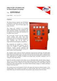
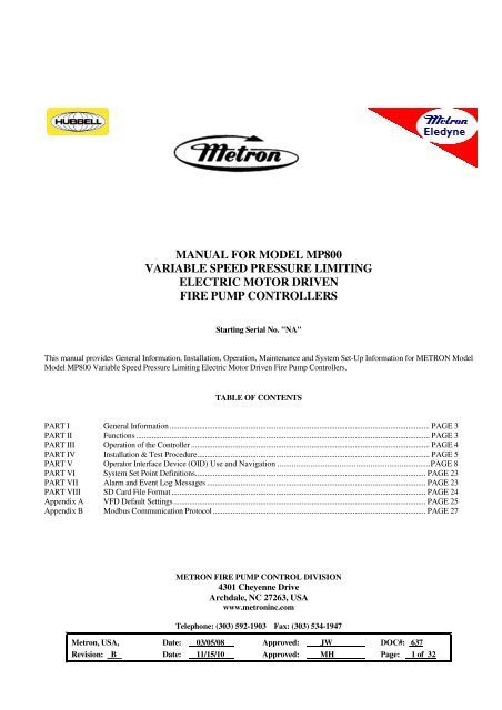
MANUAL FOR MODEL MP800<br />
VARIABLE SPEED PRESSURE LIMITING<br />
ELECTRIC MOTOR DRIVEN<br />
FIRE PUMP CONTROLLERS<br />
Starting Serial No. "NA"<br />
This <strong>manual</strong> provides General In<strong>for</strong>mation, Installation, Operation, Maintenance and System Set-Up In<strong>for</strong>mation <strong>for</strong> METRON Model<br />
Model MP800 Variable Speed Pressure Limiting Electric Motor Driven Fire Pump Controllers.<br />
TABLE OF CONTENTS<br />
PART I General In<strong>for</strong>mation .................................................................................................................................... PAGE 3<br />
PART II Functions ..................................................................................................................................................... PAGE 3<br />
PART III Operation of the Controller ......................................................................................................................... PAGE 4<br />
PART IV Installation & Test Procedure ...................................................................................................................... PAGE 5<br />
PART V Operator Interface Device (OID) Use and Navigation .......................................................................... PAGE 8<br />
PART VI System Set Point Definitions..................................................................................................................... PAGE 23<br />
PART VII Alarm and Event Log Messages ............................................................................................................... PAGE 23<br />
PART VIII SD Card File Format ................................................................................................................................. PAGE 24<br />
Appendix A VFD Default Settings ................................................................................................................................ PAGE 25<br />
Appendix B Modbus Communication Protocol ............................................................................................................ PAGE 27<br />
METRON FIRE PUMP CONTROL DIVISION<br />
4301 Cheyenne Drive<br />
Archdale, NC 27263, USA<br />
www.metroninc.com<br />
Telephone: (303) 592-1903 Fax: (303) 534-1947<br />
<strong>Metron</strong>, USA, Date: 03/05/08 Approved: JW DOC#: 637<br />
Revision: B Date: 11/15/10 Approved: MH Page: 1 of 32
THIS PAGE IS BLANK<br />
Page 2 of 32
PART I: GENERAL INFORMATION<br />
The basic function of the <strong>model</strong> MP800 Variable Speed Pressure Limiting Fire Pump Controller <strong>for</strong> electric motor driven fire pumps<br />
is to automatically start the fire pump electric motor upon a drop in <strong>pressure</strong> in the water main, or from a number of other demand<br />
signals and maintain a specific discharge <strong>pressure</strong> in the system by precisely controlling the <strong>speed</strong> of the motor. This controller<br />
provides alarm and/or alarm shutdown protection <strong>for</strong> various motor and power failures. Stopping of the motor after the demand<br />
period is over may be either <strong>manual</strong> or automatic. This controller also includes an automatic weekly test starting feature.<br />
PART II: FUNCTIONS<br />
Equipment is provided in the Controller to provide the following functions:<br />
A. Automatic Starting From:<br />
a. Drop in water line <strong>pressure</strong><br />
b. Operation of optional remote start switches, such as remote start switch, deluge valve switch, fire alarm switch, etc.<br />
c. Weekly test timer<br />
B. OID – Operator Interface Device - Provided <strong>for</strong> display of alarm functions, system <strong>pressure</strong>, 3 phase AC volts, 3 phase motor<br />
current and alarm conditions, etc. Also features a 4 line by 20 character LCD <strong>for</strong> display<br />
C. Alarms and Signal Lights - Fifteen (15) standard lights are provided to give visual signals <strong>for</strong>; "Power On”, "System Fault”,<br />
“Phase Failure", "Phase Reversal", “Pump Running”, "Pump Failed to Start", "Motor Overload", "Low Pressure",<br />
"Motor Lockout", “Local Start”, “Remote Start”, “Deluge Start”, “VFD Drive Fault”, “Bypass Mode ON”, “High<br />
Discharge Pressure” and “Drive Failure”. When a transfer switch is supplied, additional lights are provided <strong>for</strong> “Transfer<br />
Switch in Normal”, “Transfer Switch in Emergency” and “Emergency Isolation Switch/Circuit Breaker Open”. 7<br />
additional lights (4 when a transfer switch is supplied), configurable by the factory, are provided <strong>for</strong> "Pump Room Alarms".<br />
An audible alarm horn is mounted on the front of the cubicle <strong>for</strong> sounding in the event of failure. Terminals are provided <strong>for</strong><br />
remote failure indication of the following:<br />
"Power Available"<br />
"Phase Reversal"<br />
"Pump Running"<br />
"Controller Not in Auto"<br />
"VFD Drive Fault"<br />
"Bypass Mode On"<br />
"High Discharge Pressure"<br />
D. A data logger is provided as standard to record system <strong>pressure</strong> along with numerous alarm conditions and system events. The<br />
data can be displayed on the OID or can be downloaded to a PC through the RS485 port provided on the main system board.<br />
Data is stored on an SD Memory card. This card contains individual <strong>pressure</strong> files with each file containing one days worth of<br />
<strong>pressure</strong> data. Each file is of the PressXXX.txt <strong>for</strong>mat. Each entry is stamped with the date and time and system <strong>pressure</strong> at that<br />
time. The Events.txt file contains all of the logged events with each event stamped with date and time. The SD memory card can<br />
be removed and files transferred directly to a PC using appropriate memory card reader. The controller will continue to operate<br />
normally with the SD card removed. The SD card must be installed in the unit when it is powered on <strong>for</strong> the<br />
microprocessor to boot up normally. There will, however, be a visual and audible alarm when the card is removed. Events and<br />
<strong>pressure</strong> data will continue to be logged while the card is missing. The memory cards should be replaced within 12 hours to<br />
ensure that no data is lost.<br />
E. A weekly test timer is supplied to automatically start the pump any set day of the week, at a set time of day, and a preset run<br />
time. See System Config Screen 106.<br />
F. “Start” Push button – A green push button is provided on the exterior of the cabinet to <strong>manual</strong>ly start the pump. When this<br />
button is pressed, the motor will continue to run until it is stopped using the Stop push button.<br />
G. "Stop" Push button - A red pushbutton is provided on the exterior of the cabinet to stop the pump in Automatic only after<br />
starting causes have returned to normal. This returns the controller to the automatic position. In the Manual mode this will also<br />
stop the pump after starting via the Start push button.<br />
H. Cabinet - A heavy gauge steel cubicle encloses the controller.<br />
Page 3 of 32
PART III: OPERATION OF THE CONTROLLER<br />
A. When the controller is powered up, the main circuit breaker and isolation switch are in the "On" position, the controller is in<br />
standby condition ready to start the pump automatically. The Power On light should be ON indicating that all power is available<br />
and the controller is ready to start the pump.<br />
When the water <strong>pressure</strong> drops below a level, which is set in System Config Screen 101, the Controller will actuate the VFD<br />
module and run the motor at a <strong>speed</strong> that corresponds to the <strong>pressure</strong> limit set on the VFD unit. If the VFD is unable to keep the<br />
<strong>pressure</strong> above the Low Pressure alarm point, the Bypass Mode will be activated. If the pump fails to start after a set time delay<br />
(Screen #103), the "Pump Failed to Start" light will illuminate, and the alarm horn will sound. In addition, the "System<br />
Fault” light will illuminate.<br />
If the VFD\Bypass Mode selector switch is in the “Bypass Mode”, the motor will start according to the mode set in Screen #301<br />
<strong>for</strong> the Bypass Mode, and run the motor at full <strong>speed</strong>.<br />
The panel is wired so that optional remote start switches may be used, such as Deluge Valve, Remote Start pushbutton, Fire<br />
Alarm switches, etc. The Deluge Valve Switch Option (Screen #124), is a normally closed switch that when opened starts the<br />
pump similar to the <strong>pressure</strong> drop start. In addition, when “Supervisory Power Failure Startup” feature is enabled (System<br />
Config Screen 116), the Controller will automatically start the pump upon loss of a Separate 120VAC Supervisory Power, after<br />
an adjustable time delay (System Config Screen 117).<br />
If the pump stops while running, and there is still an auto start demand, the control will attempt to restart the pump. If the pump<br />
fails to start the "Pump Failed to Start" light will illuminate and the alarm will sound. If the motor current exceeds a set<br />
overload value (Screen #319)while the motor is running, the “Motor Overload” light will illuminate and the alarm will sound<br />
indicating motor overload.<br />
The Controller may be configured as either "Manual" or "Automatic" stop as required (System Config Screen 104).<br />
"Manual" stop is set as standard. When Automatic stop is enabled the stop timer is preset at the factory to 10 minutes. Longer<br />
time settings can be set in System Config screen 105. The current status of this setting is visible on the Main System Status<br />
Screen where the letter “A” will appear in the upper right hand corner of the screen when set to Automatic Stop and an “M” will<br />
appear when set <strong>for</strong> Manual stop. When “Automatic Stop” is disabled, the pump will continue to run even though the <strong>pressure</strong><br />
switch or other remote starting switch returns to its normal position. The pump can be stopped immediately only by pressing the<br />
"Stop" button. If set up <strong>for</strong> "Automatic" stop, the pump will be stopped automatically upon restoration to normal of whatever<br />
demand switch started the pump providing it has run at least 10 minutes or longer as set in System Config screen 105. If the<br />
demand period was less than the time set on the auto stop timer, the pump will continue to run until the timer times out and then<br />
will stop.<br />
B. When the "Test" mode button is pressed <strong>for</strong> two or more seconds, the pump will be started by causing a drop in water <strong>pressure</strong><br />
if the Solenoid Drain Valve Option (Screen #108) is selected. If the Solenoid Drain Valve Option is set to NO, the unit will start<br />
automatically similar to the Deluge Valve switch start feature. Failure alarm circuits will be operative in the "Test" mode. This<br />
method of starting provides a test of the Controller, thereby assuring proper operation when required. The pump will run<br />
continuously in this position until the "Stop" push button is pressed.<br />
C. Periodic Self Testing - The Weekly Test Start Timer can be set to give test runs on any day of the week and time of day desired.<br />
A timing element is incorporated in the controls so that when the pump starts in this manner, it will run <strong>for</strong> a definite time be<strong>for</strong>e<br />
it shuts down. See System Config Screens 109 through 112 to set the starting time and length of pump running. See item B.<br />
above. The Weekly test feature will also use the Solenoid Drain Valve option to start the pump if it is enabled as described in B.<br />
above. If Screen #113 (Stop Motor During Test on Alarm) is set to Yes, the motor will be stopped should any alarm condition<br />
occur during the weekly test operation.<br />
D. Provision <strong>for</strong> sequential starting is accomplished by the use of adjustable time delay on <strong>pressure</strong> drop starting or “Deluge Valve”<br />
starting. On Multiple Pump installations these timers are set sequentially and progressively longer in time to prevent more than<br />
one (1) pump from starting simultaneously with another pump. Failure of the lead pump to start will not prevent subsequent<br />
pumps from starting. The time delay on starting is set in System Config Screen 103.<br />
E. Emergency Manual Operation: Emergency <strong>manual</strong> operation is provided in case of failure of control circuitry. This lever is<br />
<strong>manual</strong>ly moved to the "On" position and must be <strong>manual</strong>ly latched in the "ON" position or it will return to "Off" when released.<br />
The lever should be moved from the "Off" position to the "On" position in as quickly a motion as possible to prevent burning the<br />
contacts. The circuit breaker should be turned off to disconnect the circuit be<strong>for</strong>e releasing emergency lever. This lever is <strong>for</strong><br />
emergency use only. A mechanical interlock switch is connected to the emergency lever to operate the contactor electrically when<br />
all circuitry is functioning properly. This is provided to prevent inadvertent slow closing of contactor and burning of contacts.<br />
Page 4 of 32
F. Drive Fault –Drive Failure lights – Two lights are provided to indicate problems or failure of the VFD unit. When the controller<br />
receives a command to start, the VFD line isolation contactor will close and power up the VFD. If the VFD does not power up and<br />
clear the fault contactor within the specified time delay set in screen 334, the Drive Failure light will illuminate and the controller<br />
which to Bypass mode and start the motor according to the method as described below. If after the VFD has powered up and starts<br />
the motor and a fault should occur during motor operation, the Drive Fault light will illuminate, the controller will stop the motor<br />
and restart it in Bypass mode according to the method as described below.<br />
G. MP300 Across-the-Line Bypass: When the controller switches to the bypass mode due to VFD failure or other factors as listed<br />
elsewhere in this <strong>manual</strong>, the controller will start the motor across the line.<br />
H. MP450 Autotrans<strong>for</strong>mer Bypass: When the controller switches to the bypass mode due to VFD failure or other factors as<br />
listed elsewhere in this <strong>manual</strong>, the controller will start the motor using an autotrans<strong>for</strong>mer reduced voltage start sequence. The<br />
autotrans<strong>for</strong>mer main contactor and the autotrans<strong>for</strong>mer neutral contactor will close immediately on bypass mode initiation. This<br />
connects the motor leads through the autotrans<strong>for</strong>mer to reduce the voltage to the motor. After the transition time delay the run<br />
contactor closes and then the start contactor and autotrans<strong>for</strong>mer neutral contactor open, thus connecting the motor to full voltage.<br />
The motor will now run at full <strong>speed</strong> and deliver rated horsepower to the load.<br />
I. Series MP700 Solid State Soft Start Bypass: When the controller switches to the bypass mode due to VFD failure or other<br />
factors as listed elsewhere in this <strong>manual</strong>, the controller will start the motor using a solid state soft start module. There are two<br />
contactors <strong>for</strong> solid state soft starting. The solid state starter line contactor will close immediately on initiation of bypass mode<br />
and ramp the motor up to <strong>speed</strong> depending on the solid state starter configuration parameters. After the transition time delay the<br />
run contactor closes and bypasses the solid state starter, thus connecting the motor to full voltage. The motor will now run at full<br />
<strong>speed</strong> and deliver rated horsepower to the load. When the stop command is received and the controller is set up <strong>for</strong> the ramp stop<br />
option (Screen #106) the motor will ramp down in <strong>speed</strong> over a fixed time delay (Screen #107) until it stops.<br />
Note: When using the emergency <strong>manual</strong> start handle, the soft start unit may display an “OCF” fault condition. This is<br />
normal. The unit is not malfunctioning. When the proper stop sequence is used according to paragraph E above, the fault<br />
condition will be cleared and the soft start unit will be ready <strong>for</strong> a normal start.<br />
A. INSTALLATION<br />
PART IV: INSTALLATION AND TEST PROCEDURE<br />
The Fire Pump Controller has been assembled and wired at the factory in accordance with the highest workmanship standards.<br />
All circuits and functions have been thoroughly tested to assure correct operation when properly installed. The installer should<br />
be completely familiar with the external hookup of the pump junction box to the terminal bar in the Controller. All local electric<br />
codes should be used <strong>for</strong> proper installation, wiring and grounding of the controller prior to startup.<br />
An optional weekly test drain solenoid valve may be provided to relieve water <strong>pressure</strong> to the <strong>pressure</strong> transducer thus initiating<br />
the start sequence. This test simulates an actual start demand. Since the Controller operates the drain valve only momentarily, a<br />
small amount of water is drained off. The water <strong>pressure</strong> sensing line to the Controller from the pump must be thoroughly<br />
flushed be<strong>for</strong>e connection to the Controller in order to remove chips, particles, or other matter, that could enter the plumbing<br />
components in the Controller.<br />
Controllers configured with "Automatic Stop" enabled may be changed to "Manual" stop by disabling this feature in System<br />
Config Screen 104. If deluge valve switches are to be used <strong>for</strong> starting, enable the Deluge Valve Option in Config Screen 121<br />
and connect the remote normally closed switch to terminals 74 and 111.<br />
B. TEST PROCEDURE<br />
All of the following tests should be made on each unit after installation. If each test is satisfactory, the operator may depend<br />
upon the panel operating properly when required. Also, any one or all of these tests may be carried out at any time after<br />
installation, if so desired. NOTE: If the Supervisory Power Failure Start Option has been Enabled (Screen #116) and 115<br />
Volts A.C. is not connected to Controller, the "System Fault" light will illuminate and the controller will start<br />
automatically after a time delay. The 115VAC must be turned on to prevent the pump from starting.<br />
Phase Reversal Alarm – Upon initial power up, if a phase reversal alarm should sound, the following process can be used to<br />
correct the alarm. If a test of the motor rotation indicates that the motor is turning opposite of the correct direction, the motor<br />
leads must be reversed to cure the condition. Turn the controller circuit breaker and isolation switch off and verify that incoming<br />
power on the load side of the controller isolation switch has been disconnected. Then reverse any two of the motor leads. Then<br />
turn the controller isolation switch and circuit breaker back on and check <strong>for</strong> correct rotation of the motor and then follow the<br />
procedure below to correct the Phase Reversal alarm.<br />
Page 5 of 32
If the motor is turning the correct direction but there is a Phase Reversal alarm then this can be corrected as follows. Press the<br />
Config button on the front of the OID. Press the Config (2) button again to access the User Preferences Setup screens. Press the<br />
Down arrow key until the OID reads “223 User Preferences – Reversed Phase”. Press the Change/Enter button. The system will<br />
then ask <strong>for</strong> a password. Enter 1111. Press the Up or Down arrow key to change the setting in the lower left hand corner of the<br />
screen from “No” to “Yes” then press the Change/Enter button. After a few seconds the “Phase Reversal” LED will reset. Also,<br />
press the Silence\ Reset button <strong>for</strong> approx. 3 seconds to silence the audible alarm.<br />
INPUT/OUTPUT STATUS INDICATOR LIGHTS<br />
Light Emitting Diodes (L.E.D.) lights have been installed on the microprocessor module to indicate the status of each input and<br />
output terminal. Status indication <strong>for</strong> the standard functions is given below:<br />
Terminal Number<br />
(Microprocessor Func #)<br />
(Out 01)<br />
(Out 02)<br />
(Out 03)<br />
(Out 04)<br />
(Out 05)<br />
(Out 06)<br />
(In 01)<br />
(In 02)<br />
(In 03)<br />
(In 05)<br />
(In 06)<br />
(In 07)<br />
(In 08)<br />
(In 09)<br />
(In 19)<br />
(In 20)<br />
(In 21)<br />
L.E.D. (light) "ON" Indication<br />
Alarm Horn<br />
Circuit Breaker Shunt Trip<br />
VFD line Contactor relay<br />
VFD load Contactor relay<br />
Run Enable signal to VFD<br />
Start/Stop signal to VFD<br />
Emergency Start lever activated<br />
Start Pushbutton<br />
Stop Pushbutton<br />
VFD Load Contactor closed<br />
Transfer Switch position (if applicable)<br />
Transfer Switch ready to transfer (if applicable)<br />
Transfer Switch Emergency Iso Switch Open (if applicable)<br />
VFD Fault Input<br />
VFD Running<br />
VFD\Bypass Selector Switch<br />
Bypass Contactor Closed<br />
a. AUTOMATIC STARTING TESTS:<br />
1. Set VFD\Bypass Switch to Bypass Mode.<br />
2. Bleed off <strong>pressure</strong> in system until <strong>pressure</strong> drops below the low set point.<br />
3. Pump should start according to the start mode (see Part III F-G) automatically and continue to run after <strong>pressure</strong> rises<br />
above the high set point, if arranged <strong>for</strong> "Manual" stop. If arranged <strong>for</strong> "Automatic" stop, pump will continue to run<br />
<strong>for</strong> time set on Auto Stop Timer and then stop.<br />
4. Press the "Stop" push button to stop the pump.<br />
5. Repeat tests <strong>for</strong> each demand switch such as deluge valve (if enabled), remote start, etc.<br />
b. PERIODIC WEEKLY START TEST:<br />
1. Pressure must be up and all other demand switches de-activated.<br />
2. When the current day and time of day matches the settings in System Config screens 107 and 108, the solenoid drain<br />
valve will energize (if enabled and supplied, see screen #108) and the pump will start. It will continue to run <strong>for</strong> the<br />
amount of time set and then stop automatically.<br />
c. SETTING PROGRAM WEEKLY TEST TIME: System Config screen 109 through 112.<br />
d. REMOTE START SWITCH CIRCUITS: Field wiring terminals are provided on the controller so that optional remote<br />
start switches such as Remote Pushbutton Stations, Deluge Valve Switch, Fire Alarm Switches, etc., may be used to start the<br />
pump. Two (2) sets of terminals are provided. Terminals #112 and #31 are used <strong>for</strong> remote <strong>manual</strong> start push buttons (close<br />
to start). Terminals #111 and #31 are used <strong>for</strong> remote Deluge Valve Switch or other remote automatic start switches (open to<br />
start). Upon automatic start from this type of switch, the pump will be stopped either automatically after the demand switch<br />
de-activates and Pump Auto Stop Timer times out, or <strong>manual</strong>ly at the Controller. Terminals #111 and #31 must have a<br />
Page 6 of 32
jumper installed if a remote Deluge switch is “Enabled” but not to be used. When the controller is shipped from the factory<br />
Deluge Valve start is Disabled (System Config screen 121).<br />
e. AC POWER FAILURE STARTING: If this feature has been enabled it can be tested by disconnecting the supervisory<br />
power 115 V.A.C. to the Controller. After the preset time delay (which is specified in System Config screen 112), the<br />
Controller will commence starting of the pump. The "System Fault" LED will illuminate and the alarm will sound.<br />
f. NORMAL OPERATION – AUTOMATIC: The pump will automatically start upon drop in <strong>pressure</strong> or operation of other<br />
start switches. If the Auto Stop Timer is disabled (Manual Stop) the pump must be turned off at the Controller. When the<br />
Auto Stop Timer is enabled, upon termination of the demand signal, the pump will run <strong>for</strong> the length of time left on the Auto<br />
Stop Timer and then will stop automatically.<br />
g. AN ADJUSTABLE SEQUENTIAL START TIMER IS SUPPLIED FOR MULTIPLE PUMP INSTALLATION:<br />
Normally, the leading pump Controller will not have a delay timer and will commence starting of the pump immediately<br />
upon operation of a demand signal (other than Power Failure which is time delayed). The subsequent Controllers will have a<br />
time delay which is adjustable from 0 to 999 seconds. Each time delay should be set with progressively longer times on each<br />
subsequent pump. The recommended time interval is ten (10) to fifteen (15) seconds. This may be extended or shortened as<br />
required by the local authorities having jurisdiction.<br />
h. PUMP ROOM ALARMS: Field terminals may be provided <strong>for</strong> various inputs from pump room alarms. These alarms<br />
include: Low Pump Room Temperature, Reservoir Low, Reservoir Empty, Low Suction Pressure, Relief Valve Discharge<br />
and/or Flow Meter On etc. A maximum of eight (8) (or five (5) if a transfer switch is supplied), pump room alarms is<br />
available. Each auxiliary alarm is configurable so that the alarm horn may or may not sound and the light will come on when<br />
the alarm sensor contacts close. These pump room alarms can be silenced with the “Silence” push button on the OID if they<br />
have been configured as silenceable.<br />
i. Variable Frequency Drive (VFD) – The VFD constantly monitors the actual <strong>pressure</strong> in the system via the Pressure<br />
Transducer, and compares this signal to the set point value. If the actual <strong>pressure</strong> is less than the set point, the VFD will<br />
increase its output frequency to cause the motor to <strong>speed</strong> up. If the actual <strong>pressure</strong> is greater than the set point, the VFD<br />
will decrease its output frequency to slow the motor down. Consequently, the motor will run at whatever <strong>speed</strong> is<br />
necessary to maintain the set point <strong>pressure</strong>. All PID control is per<strong>for</strong>med by the VFD. All parameters <strong>for</strong> PID control<br />
have been adjusted at the factory prior to shipment and should not require further adjustment. If adjustment is desired, it<br />
is strongly recommended that this only be carried out by qualified individuals with assistance from factory personnel. All<br />
motor specific data such as RPM, Volts, Frequency, Horsepower, FLA, etc… must be entered to the VFD at the time of<br />
initial installation, to ensure proper operation. The set point <strong>pressure</strong> may have to be reset in the field however. See the<br />
separate <strong>manual</strong> provided with the VFD unit <strong>for</strong> instructions on how to adjust this setting.<br />
Note: Once the start-up testing is complete, please fill in the critical settings label on the inside of the main door with the<br />
following in<strong>for</strong>mation: Pressure Limit Set Point, Pump Start Pressure and Pump Stop Pressure.<br />
Page 7 of 32
PART V: OPERATOR INTERFACE DEVICE (OID) USE AND NAVIGATION<br />
The Operator Interface Device (OID) provides visual indication of the alarms, status of system parameters, and an interface to<br />
change set points to configure the controller to operate appropriately <strong>for</strong> various installation requirements.<br />
Labeled LED<br />
Annunciator<br />
Common Tasks Per<strong>for</strong>med Using The OID<br />
Silencing Horn: If a horn is sounding and the alarm is silenceable, a quick press<br />
of the [SILENCE/LAMP TEST] will silence the horn (less than 1 second press).<br />
Resetting Alarms: If the alarm condition has cleared, press and hold the<br />
[RESET/ESC] button 2 to 5 seconds to reset alarms.<br />
Test Mode: Pressing and holding the [TEST] button <strong>for</strong> two or more seconds<br />
will open the <strong>pressure</strong> drain solenoid, if supplied, thus dropping the <strong>pressure</strong>,<br />
which causes the controller to start the pump. Pressing and releasing the [TEST]<br />
button, if the solenoid drain valve is not supplied, will activate the start sequence<br />
through software control only.<br />
Lamp Test: To illuminate and check all the OID LED’s and the horn, press and<br />
hold the [SILENCE/LAMP TEST] button 5 or more seconds or until all the<br />
lights turn on.<br />
System Operation and<br />
Control Type Buttons<br />
LCD Digital Display<br />
Page 8 of 32
OID Screen Map<br />
METRON OID100<br />
POWER<br />
1<br />
2<br />
3<br />
SYSTEM<br />
STATUS<br />
SYSTEM<br />
LOGS<br />
CONFIG<br />
PRINT<br />
CHANGE/<br />
ENTER<br />
TEST<br />
RESET/<br />
ESC<br />
SILENCE/<br />
LAMP<br />
TEST<br />
1 SYSTEM STATUS B1<br />
PRES STRT AB 460V<br />
110 100 BC 461V<br />
psi psi AC 460V<br />
SYSTEM LOGS<br />
1) Event Log<br />
2) Pressure Log<br />
1 CONFIG<br />
1) SYSTEM SETPOINTS<br />
2) USER PREFERENCES<br />
3) TECH SCREENS<br />
2 SYSTEM STATUS<br />
Phase A 125 Amps<br />
Phase B 124 Amps<br />
Phase C 125 Amps<br />
2 CONFIG<br />
1) ANALOG SIGNALS<br />
2) AUXILLIARY ALARMS<br />
3 SYSTEM STATUS<br />
Pump Countdown Tmr<br />
0min Until Start<br />
0min Until Stop<br />
4 SYSTEM STATUS<br />
Pump run Hr 0.0<br />
# of Starts 0<br />
Fri12/15/05 09:51:38<br />
5 SYSTEM STATUS<br />
Controller Power<br />
On Time: 18.5 Hrs<br />
Mon10/20/04 17:53:26<br />
# 1 EVENT LOG<br />
System in Off<br />
Mode Occurred<br />
10/16/04 13:15:15<br />
# 1 EVENT DETAILS<br />
System in Off<br />
Mode Occurred<br />
10/16/04 13:15:15<br />
# 1 EVENT DETAILS<br />
Pressure: 83.2psi<br />
System Auto:Yes<br />
Pump Running:No<br />
PRESSURE LOG<br />
10/16/04 17:52:45<br />
112 psi<br />
Skip Rate:[EACH ]<br />
PRESSURE LOG<br />
10/16/04 17:52:30<br />
112 psi<br />
Skip Rate:[EACH ]<br />
PRESSURE LOG<br />
10/16/04 17:52:15<br />
113 psi<br />
Skip Rate:[EACH ]<br />
Continued on next<br />
page.<br />
6 SYSTEM STATUS<br />
Firmware Ver SV 1.1<br />
Commissioned Date:<br />
10/15/04<br />
# 1 EVENT DETAILS<br />
Phase A Amps 0<br />
Phase B Amps 0<br />
Phase C Amps 0<br />
| |<br />
| |<br />
| |<br />
# 1 EVENT DETAILS<br />
Phase AB Volt 460<br />
Phase BC Volt 461<br />
Phase AC Volt 464<br />
# 2 EVENT LOG<br />
Pump Failed To<br />
Start Alarm Occurred<br />
10/16/04 07:32:15<br />
# 3 EVENT LOG<br />
Supvr Power Failure<br />
Alarm Cleared<br />
10/16/04 07:09:48<br />
| |<br />
| |<br />
| |<br />
Page 9 of 32
OID Screen Map (continued)<br />
1 CONFIG<br />
1) SYSTEM SETPOINTS<br />
2) USER PREFERENCES<br />
3) TECH SCREENS<br />
2 CONFIG<br />
1) ANALOG SIGNALS<br />
2) AUXILLIARY ALARMS<br />
101 SYSTEM SETPOINTS<br />
Pump Start<br />
Pressure<br />
[100.0]psi 0-999.9<br />
201 USER PREFERENCES<br />
Set System Real<br />
Time Clock<br />
[17:03:52]<br />
301 TECH SCREENS<br />
Controller Model<br />
Number<br />
[ MP300]<br />
400 ANALOG SIGNALS<br />
Analog Input 01<br />
Slope:<br />
[0.2135678]<br />
501 AUX USER PROGRAM<br />
AUX# 1<br />
Enabled<br />
[Yes]<br />
102 SYSTEM SETPOINTS<br />
Pump Stop<br />
Pressure<br />
[110.0]psi 0-999.9<br />
202 USER PREFERENCES<br />
Set System Date<br />
[02/16/03]<br />
302 TECH SCREENS<br />
Transfer Switch<br />
Supplied<br />
[Yes]<br />
401 ANALOG SIGNALS<br />
Analog Input 01<br />
Offset:<br />
[- 75.2568]<br />
502 AUX USER PROGRAM<br />
AUX# 1<br />
Input Number<br />
[51] 0-40<br />
103 SYSTEM SETPOINTS<br />
Pump Start<br />
Delay Time<br />
[ 10] seconds 0-999<br />
203 USER PREFERENCES<br />
Set System Day<br />
Of The Week<br />
[Sun]<br />
303 TECH SCREENS<br />
Nominal System<br />
Voltage<br />
[480]VAC 120-7200<br />
402 ANALOG SIGNALS<br />
Analog Input 1 651<br />
Minimum Counts<br />
[ 200]<br />
503 AUX USER PROGRAM<br />
AUX# 1<br />
Input Contact Type<br />
[NO ]<br />
104 SYSTEM SETPOINTS<br />
Pump Automatic<br />
Stop Enabled<br />
[Yes]<br />
204 USER PREFERENCES<br />
Log System Pressure<br />
Drop Events<br />
[Yes]<br />
304 TECH SCREENS<br />
CPT Primary Voltage<br />
Rating<br />
[ 480] 120-7200<br />
403 ANALOG SIGNALS<br />
Analog Input 01 651<br />
Maximum Counts<br />
[ 800]<br />
504 AUX USER PROGRAM<br />
AUX# 1<br />
Trip Time<br />
[ 0]sec 0-999<br />
105 SYSTEM SETPOINTS<br />
Pump Minimum<br />
Run Time<br />
[30]minutes 30-99<br />
205 USER PREFERENCES<br />
Low Pressure Event<br />
Trip Pressure<br />
[5]psi 0-999.9<br />
305 TECH SCREENS<br />
Current Trans<strong>for</strong>mer<br />
Ratio<br />
[1200] /5 1-9999<br />
404 ANALOG SIGNALS<br />
Analog Input 1 651<br />
Minimum PSI<br />
[ 3] 0-10<br />
505 AUX USER PROGRAM<br />
AUX# 1<br />
Reset Time<br />
[ 0]sec 0-999<br />
106 SYSTEM SETPOINTS<br />
Ramp Stop Option<br />
MP700<br />
[Yes]<br />
206 USER PREFERENCES<br />
System Pressure Drop<br />
Event Time Span<br />
[15] seconds 0-20<br />
306 TECH SCREENS<br />
Restart Time<br />
Delay<br />
[ 3]sec 0-99<br />
405 ANALOG SIGNALS<br />
Analog Input 02<br />
Slope<br />
[ 0.0094996]<br />
506 AUX USER PROGRAM<br />
AUX# 1<br />
Auto Reset Enabled<br />
[Yes]<br />
107 SYSTEM SETPOINTS<br />
Ramp Stop Option<br />
Time<br />
[10]sec 1-99<br />
207 USER PREFERENCES<br />
Time Between<br />
Pressure Log Samples<br />
[ 15] seconds 15-999<br />
307 TECH SCREENS<br />
Motor Full Load<br />
Amps<br />
[ 124]Amps 0-999<br />
406 ANALOG SIGNALS<br />
Analog Input 02<br />
Offset<br />
[-75.2568]<br />
507 AUX USER PROGRAM<br />
AUX# 1<br />
Horn Enabled<br />
[No ]<br />
108 SYSTEM SETPOINTS<br />
Solenoid Drain<br />
Valve Option<br />
[Yes]<br />
208 USER PREFERENCES<br />
Auto Print Each<br />
Pressure Log Sample<br />
[No ]<br />
308 TECH SCREENS<br />
Low Voltage<br />
Trip Percent<br />
[85]% 50-99<br />
407 ANALOG SIGNALS<br />
Analog Input 02 651<br />
Minimum Counts<br />
[ 0]<br />
508 AUX USER PROGRAM<br />
AUX# 1<br />
Horn Silence<br />
[No ]<br />
109 SYSTEM SETPOINTS<br />
Automatic Weekly<br />
Test Run<br />
[Yes]<br />
209 USER PREFERENCES<br />
Auto Print Each<br />
Event Log Entry<br />
[No ]<br />
309 TECH SCREENS<br />
Low Voltage<br />
Time Delay<br />
[ 5]sec 0-99<br />
408 ANALOG SIGNALS<br />
Analog Input 03<br />
Slope<br />
[0.0094996]<br />
509 AUX USER PROGRAM<br />
AUX# 1<br />
LED Number<br />
[19] 0-24<br />
110 SYSTEM SETPOINTS<br />
Auto Weekly Test<br />
Day Of The Week<br />
[Mon]<br />
210 USER PREFERENCES<br />
Selective Range<br />
Printing<br />
[ 1] Be<strong>for</strong>e 1-99<br />
310 TECH SCREENS<br />
High Voltage Alarm<br />
% of Nominal<br />
[125]% 0-999<br />
409 ANALOG SIGNALS<br />
Analog Input 03<br />
Offset<br />
[-75.2568]<br />
510 AUX USER PROGRAM<br />
AUX# 1<br />
Output1 Number<br />
[ 0] 0-19<br />
111 SYSTEM SETPOINTS<br />
Auto Weekly Pump<br />
Test Start Time<br />
[10:00:00]<br />
211 USER PREFERENCES<br />
Selective Range<br />
Printing<br />
[ 1] After 1-99<br />
311 TECH SCREENS<br />
High Voltage<br />
Time Delay<br />
[ 5]sec 0-99<br />
410 ANALOG SIGNALS<br />
Analog Input 03<br />
Minimum Counts<br />
[ 0]<br />
511 AUX USER PROGRAM<br />
AUX# 1<br />
Output2 Number<br />
[ 0] 0-19<br />
112 SYSTEM SETPOINTS<br />
Auto Weekly Test<br />
Length Of Run Time<br />
[30] minutes 30-99<br />
212 USER PREFERENCES<br />
High Discharge Press<br />
Alarm Option<br />
[ No]<br />
312 TECH SCREENS<br />
Phase Loss % of<br />
Nominal Voltage<br />
[70]% 0-99<br />
411 ANALOG SIGNALS<br />
Minimum Volts<br />
[10] 0-9999<br />
512 AUX USER PROGRAM<br />
AUX# 1<br />
Output3 Number<br />
[ 0] 0-19<br />
113 SYSTEM SETPOINTS<br />
Stop Motor during<br />
Test on Alarm<br />
[No]<br />
213 USER PREFERENCES<br />
High Discharge<br />
Alarm Pressure<br />
[100] 1-999<br />
313 TECH SCREENS<br />
Phase Loss<br />
Time Delay<br />
[5]sec 0-99<br />
412 ANALOG SIGNALS<br />
Phase AB Voltage<br />
Slope:<br />
[0.729750]<br />
513 AUX USER PROGRAM<br />
AUX# 1<br />
Record In Event Log<br />
[No ]<br />
114 SYSTEM SETPOINTS<br />
Supervisory Power<br />
Option<br />
[No]<br />
214 USER PREFERENCES<br />
High Discharge Alarm<br />
Time Delay<br />
[ 8]sec 0-99<br />
314 TECH SCREENS<br />
Start Transition<br />
Time Delay<br />
[ 2]sec 0-10<br />
413 ANALOG SIGNALS<br />
Phase AB Voltage<br />
Offset:<br />
[6.52430]<br />
514 AUX USER PROGRAM<br />
AUX# 1<br />
Record In Alarm Log<br />
[No ]<br />
115 SYSTEM SETPOINTS<br />
Supervisory Power<br />
Delay Time<br />
[ 2] sec 0-99<br />
215 USER PREFERENCES<br />
Low Discharge Press<br />
Alarm Option<br />
[ No]<br />
315 TECH SCREENS<br />
Single Phase Alarm<br />
% of FLA<br />
[ 5]% 0-99<br />
414 ANALOG SIGNALS<br />
Phase BC Voltage<br />
Slope:<br />
[0.729750]<br />
515 AUX USER PROGRAM<br />
AUX# 1<br />
Text Message Number<br />
[ 0] 0-27<br />
Page 10 of 32
116 SYSTEM SETPOINTS<br />
Supervisory Power<br />
Failure Startup<br />
[Yes]<br />
216 USER PREFERENCES<br />
Low Discharge<br />
Alarm Pressure<br />
[100] 0-999<br />
316 TECH SCREENS<br />
Single Phase Loss<br />
Time Delay<br />
[5]seconds 0-99<br />
415 ANALOG SIGNALS<br />
Phase BC Voltage<br />
Offset:<br />
[6.52430]<br />
117 SYSTEM SETPOINTS<br />
Supvervisory Power<br />
Fail Start Dly Time<br />
[ 1]minutes 0-500<br />
217 USER PREFERENCES<br />
Low Discharge Alarm<br />
Time Delay<br />
[15]sec 0-99<br />
317 TECH SCREENS<br />
Motor Run % of<br />
FLA<br />
[20]% 0-99<br />
416 ANALOG SIGNALS<br />
Phase AC Voltage<br />
Slope:<br />
[0.729750]<br />
118 SYSTEM SETPOINTS<br />
Pressure Transducer<br />
Failure Pump Start<br />
[ No]<br />
218 USER PREFERENCES<br />
No Load Amps %<br />
of FLA<br />
[ 5] 0-99<br />
318 TECH SCREENS<br />
Use Motor Current<br />
<strong>for</strong> Pump Running Sig<br />
[Yes]<br />
417 ANALOG SIGNALS<br />
Phase AC Voltage<br />
Offset:<br />
[6.52430]<br />
119 SYSTEM SETPOINTS<br />
Shutdown On Low<br />
Intake Pressure/Lvl<br />
[No ]<br />
219 USER PREFERENCES<br />
No Load Time<br />
Time Delay<br />
[ 8]sec 0-99<br />
319 TECH SCREENS<br />
Overload Alarm<br />
% of FLA<br />
[125]% 100-199<br />
418 ANALOG SIGNALS<br />
Minimum Amps<br />
[10] 0-9999<br />
120 SYSTEM SETPOINTS<br />
Shutdown On Low<br />
Intake Trip Time<br />
[ 0]seconds 0-999<br />
220 USER PREFERENCES<br />
LCD Back Light Mode<br />
0=Always on<br />
[0]] 1=Power Save<br />
320 TECH SCREENS<br />
Overload Alarm<br />
Time Delay<br />
[3]sec 0-99<br />
419 ANALOG SIGNALS<br />
Phase A Amps<br />
Slope:<br />
[ 2.9635]<br />
121 SYSTEM SETPOINTS<br />
Low Intake Shutdown<br />
Auto Reset<br />
[ No]<br />
221 USER PREFERENCES<br />
Language Select<br />
[English]<br />
321 TECH SCREENS<br />
Start on Single<br />
Phase Loss<br />
[Yes]<br />
420 ANALOG SIGNALS<br />
Phase A Amps<br />
Offset:<br />
[36.9270]<br />
122 SYSTEM SETPOINTS<br />
Low Intake Shutdown<br />
Auto Reset Time<br />
[ 0]seconds 0-999<br />
222 USER PREFERENCES<br />
Change User Password<br />
Level 1<br />
[****]<br />
322 TECH SCREENS<br />
Motor Run Amps<br />
Time Delay<br />
[5]sec 0-99<br />
421 ANALOG SIGNALS<br />
Phase B Amps<br />
Slope:<br />
[ 2.9635]<br />
123 SYSTEM SETPOINTS<br />
Pressure Switch<br />
Pump Start<br />
[No ]<br />
223 USER PREFERENCES<br />
Reversed Phase<br />
order (1-3-2)<br />
[No]<br />
323 TECH SCREENS<br />
Motor Start<br />
Time Delay<br />
[10]sec 0-99<br />
422 ANALOG SIGNALS<br />
Phase B Amps<br />
Offset:<br />
[36.9270]<br />
124 SYSTEM SETPOINTS<br />
Deluge Valve<br />
Pump Start<br />
[No]<br />
224 USER PREFERENCES<br />
Save Aux alarms<br />
to SD memory card<br />
[No]<br />
323A TECH SCREENS<br />
Nominal Line<br />
Frequency<br />
[60] 50-70<br />
423 ANALOG SIGNALS<br />
Phase C Amps<br />
Slope:<br />
[ 2.9635]<br />
225 USER PREFERENCES<br />
Load Aux alarms<br />
from SD memory card<br />
[No]<br />
324 TECH SCREENS<br />
Under Frequency<br />
% of Nominal<br />
[25] 0-99<br />
424 ANALOG SIGNALS<br />
Phase C Amps<br />
Offset:<br />
[36.9270]<br />
226 USER PREFERENCES<br />
Pressure Units<br />
[psi]<br />
325 TECH SCREENS<br />
Under Frequency<br />
Time Delay<br />
[5]sec 0-99<br />
ANALOG INPUT COUNTS<br />
649 1176 1221 0<br />
0 0 0 0<br />
0 0<br />
227 USER PREFERENCES<br />
Modbus address<br />
[001] 0-255<br />
326 TECH SCREENS<br />
Over Frequency<br />
% of Nominal<br />
[25]% 0-999<br />
Daughter board<br />
counts<br />
649 1176 1221 0<br />
0 0 0 0<br />
228 USER PREFERENCES<br />
Modbus Enabled<br />
(Disables Printer)<br />
[Yes]<br />
327 TECH SCREENS<br />
Over Frequency<br />
Time Delay<br />
[5]sec 0-99<br />
425 FACTORY PRESETS<br />
SELECT YES TO LOAD<br />
DEFAULT SETTINGS<br />
No<br />
229 USER PREFERENCES<br />
Modbus/Printer Baud<br />
[38400]<br />
230 USER PREFERENCES<br />
Modbus Parity<br />
[Even]<br />
328 TECH SCREENS<br />
Alarm log 31/2<br />
Event log 50/ 4<br />
Pr. log 0/29333<br />
329 TECH SCREENS<br />
System Commissioned<br />
Date<br />
[00/00/00]<br />
426 USER PREFERENCES<br />
Load all settings<br />
from SD Card<br />
[No]<br />
427 USER PREFERENCES<br />
Save all settings<br />
to SD Card<br />
[No]<br />
330 TECH SCREENS<br />
Change Tech Password<br />
[******]<br />
331 TECH SCREENS<br />
Password Logout<br />
Time<br />
[5]min 1-15<br />
332 TECH SCREENS<br />
VFD Line Isolation<br />
deactivation<br />
[10]min 1-15<br />
333 TECH SCREENS<br />
Mode Select<br />
0=US, 1=EU<br />
[0]<br />
334 TECH SCREENS<br />
Drive Ready<br />
Timer<br />
[12] seconds 0-99<br />
Page 11 of 32
The [SYSTEM STATUS], [SYSTEM LOGS], and [CONFIG] buttons navigate the user to the top screen of a column of similarly<br />
grouped screens or menus.<br />
SYSTEM STATUS: The [SYSTEM STATUS] button can be pressed at any time to return the screen to the home System Status<br />
screen #1. System Status screens display the real time in<strong>for</strong>mation <strong>variable</strong>s about the pump system.<br />
SYSTEM LOGS: The [SYSTEM LOGS] button displays the System Logs menu. Once the menu is displayed, buttons with<br />
numbers on them can be used to enter the selected data log. See the following page <strong>for</strong> details on navigating the System<br />
Logs.<br />
CONFIGURATION: The [CONFIG] button displays the Config menu which groups the different types of set points that<br />
configure the system to operate in the desired manner. Use the [UP] and [DOWN] buttons to scroll between the two menu<br />
screens. Buttons with numbers on them can be used to enter the selected configuration screen group. See the System<br />
Setpoint Definitions section <strong>for</strong> descriptions on the functionality of each set point.<br />
1 SYSTEM STATUS B1<br />
PRES STRT AB 460V<br />
110 100 BC 461V<br />
psi psi AC 460V<br />
2 SYSTEM STATUS<br />
Phase A 125 Amps<br />
Phase B 124 Amps<br />
Phase C 125 Amps<br />
3 SYSTEM STATUS<br />
Pump Countdown Tmr<br />
0sec Until Start<br />
0min Until Stop<br />
4 SYSTEM STATUS<br />
Pump Run Hrs: 5.3<br />
# Of Starts: 8<br />
Mon 10/17/04 17:53:26<br />
5 SYSTEM STATUS<br />
Controller Power<br />
On Time 18.5 Hrs<br />
10/15/04 17:53:26<br />
6 SYSTEM STATUS<br />
Firmware Ver SV 1.1<br />
Commissioned Date:<br />
11/15/02<br />
SYSTEM LOGS<br />
1) Event Log<br />
2) Pressure Log<br />
# 1 EVENT LOG<br />
System in Auto<br />
Mode Occurred<br />
10/16/04 13:15:15<br />
PRESSURE LOG<br />
10/16/04 17:52:45<br />
112 psi<br />
Skip Rate:[EACH ]<br />
See the following page <strong>for</strong> an example of<br />
scrolling through the Alarm, Event, and<br />
Pressure Logs<br />
1 CONFIG<br />
1) SYSTEM SETPOINTS<br />
2) USER PREFERENCES<br />
3) TECH SCREENS<br />
2 CONFIG<br />
1) ANALOG SIGNALS<br />
2) AUXILLIARY ALARMS<br />
101 SYSTEM SETPOINTS<br />
Pump Start<br />
Pressure<br />
[100.0]psi 0-999.9<br />
201 USER PREFERENCES<br />
Set System Real<br />
Time Clock<br />
[17:03:52]<br />
301 TECH SCREENS<br />
Controller Model<br />
Number<br />
[MP300]<br />
401 ANALOG SIGNALS<br />
Analog Input 01<br />
Slope:<br />
[0.21346771]<br />
501 AUX USER PROGRAMS<br />
AUX# 1<br />
Enabled<br />
[Yes]<br />
Page 12 of 32
SYSTEM LOGS: The Model MP Electric controller has three separate data logs; 1) alarm log, 2) event log, and 3) <strong>pressure</strong> log.<br />
The alarm log is a subset of the event log and only displays the last ten alarms that have occurred or cleared. The event log<br />
records all alarm and system function type events<br />
SYSTEM LOGS<br />
1) Event Log<br />
2) Pressure Log<br />
SYSTEM LOGS: The [UP] and [DOWN] arrow buttons can be used to scroll through the<br />
three data logs. The [CHANGE/ENTER] button enters and exits the alarm/event details in<br />
either the Alarm or Event logs. In the Pressure Log the [CHANGE/ENTER] button changes<br />
the skip rate used to scroll through the logged <strong>pressure</strong> readings.<br />
# 1 EVENT LOG<br />
System in Auto<br />
Mode Occurred<br />
10/16/04 13:15:15<br />
# 1 EVENT DETAILS<br />
System in Auto<br />
Mode Occurred<br />
10/16/04 13:15:15<br />
# 1 EVENT DETAILS<br />
AB V 460 A 32<br />
BC V 461 B 32<br />
AC V 460 C 33<br />
# 1 EVENT DETAILS<br />
Pump Running: Yes<br />
PRESSURE LOG<br />
10/16/04 17:52:45<br />
112 psi<br />
Skip Rate:[EACH ]<br />
PRESSURE LOG<br />
10/16/04 17:52:30<br />
112 psi<br />
Skip Rate:[EACH ]<br />
PRESSURE LOG<br />
10/16/04 17:52:15<br />
113 psi<br />
Skip Rate:[EACH ]<br />
# 2 EVENT LOG<br />
Pump Failed To<br />
Start Alarm Occurred<br />
10/16/04 07:32:15<br />
# 3 EVENT LOG<br />
Superv Power Failure<br />
Alarm Cleared<br />
10/16/04 07:09:48<br />
Page 13 of 32
Printing System Log Data: The following applies if a printer has been connected to the RS485 port using the appropriate cable.<br />
When the [PRINT] button is pressed when looking at data in one of the three logs, a menu <strong>for</strong> what is to be printed is displayed.<br />
Pressing [1] prints just the alarm/event/<strong>pressure</strong> reading currently being displayed. Pressing [2] prints a range of data be<strong>for</strong>e and<br />
after the currently displayed alarm/event/<strong>pressure</strong> reading currently displayed. The range can be changed in the User Preferences<br />
setpoints 210 and 211. When the print button on the OID is pressed, data will be sent to the PC via the port you have connected<br />
to.<br />
#1 EVENT LOG<br />
Superv Power Failure<br />
Alarm Occurred On<br />
10/16/04 07:32:15<br />
#1 EVENT LOG<br />
Superv Power Failure<br />
Alarm Occurred On<br />
10/16/04 07:32:15<br />
#1 EVENT DETAILS<br />
Superv Power Failure<br />
Alarm Occurred On<br />
10/16/04 07:32:15<br />
#1 EVENT DETAILS<br />
AB V 460 A 32<br />
BC V 461 B 32<br />
AC V 460 C 33<br />
# 1 EVENT DETAILS<br />
Pump Running: Yes<br />
Pressure: 118 psi<br />
PRESSURE LOG<br />
01/01/03 17:52:45<br />
600 psi<br />
Skip Rate:[EACH ]<br />
PRESSURE LOG<br />
01/01/03 17:52:30<br />
599 psi<br />
Skip Rate:[EACH ]<br />
PRINT OPTIONS<br />
1) PRINT THIS EVENT<br />
2) PRINT EVENT RANGE<br />
10 BEFORE,10 AFTER<br />
PRINT OPTIONS<br />
1) PRINT THIS EVENT<br />
2) PRINT EVENT RANGE<br />
10 BEFORE,10 AFTER<br />
PRINT OPTIONS<br />
1) PRINT THIS ENTRY<br />
2) PRINT ENTRY RANGE<br />
10 BEFORE,10 AFTER<br />
Typical Event/Alarm Log<br />
Message Printout<br />
#1 EVENT LOG<br />
AC Power Restored<br />
Occurred On<br />
11/16/02 07:32:15<br />
#2 EVENT LOG<br />
AC Power Restored<br />
Occurred On<br />
11/16/02 07:32:15<br />
Typical Event/Alarm Log<br />
Details Printout<br />
#1 EVENT DETAILS<br />
AC Power Restored<br />
Occurred On<br />
11/16/02 07:32:15<br />
AB V 460 A 32<br />
BC V 461 B 32<br />
AC V 460 C 33<br />
Pump Running:Yes<br />
Pressure: 118 psi<br />
#2 EVENT DETAILS<br />
AC Power Restored<br />
Occurred On<br />
11/16/02 07:32:15<br />
AB V 460 A 32<br />
BC V 461 B 32<br />
AC V 460 C 33<br />
Pump Running:Yes<br />
Pressure: 118psi<br />
Typical Pressure Log<br />
Printout<br />
PRESSURE LOG<br />
01/01/03 17:52:45<br />
600 psi<br />
01/01/03 17:52:30<br />
599 psi<br />
01/01/03 17:52:15<br />
599 psi<br />
01/01/03 17:52:00<br />
601 psi<br />
Page 14 of 32
CONFIGURATION SCREENS: All parameters that control the operation of the controller can be viewed and changed within<br />
the Configuration set point screens. Each set point is protected by a user password to prevent unauthorized changes. The system<br />
set points are separated into five different group<br />
s.<br />
1 CONFIG<br />
1) SYSTEM SETPOINTS<br />
2) USER PREFERENCES<br />
3) TECH SCREENS<br />
2 CONFIG<br />
1) ANALOG SIGNALS<br />
2) AUXILLIARY ALARMS<br />
1) SYSTEM SETPOINTS (Level 1 password): These setpoints adjust the conditions<br />
<strong>for</strong> starting and stopping the pump.<br />
2) USER PREFERENCES (Level 1 password): These setpoints adjust settings not<br />
related to pump operation.<br />
3) TECH SCREENS (Level 2 password): These setpoints are <strong>for</strong> factory/technician<br />
purposes only and are used to fine tune special systems.<br />
1) ANALOG SIGNALS (Level 2 password): These setpoints calibrate the analog<br />
<strong>pressure</strong>, voltage and amp readings.<br />
2) AUXILLIARY ALARMS (Level 2 password): These 12 user programs are used<br />
to setup any auxiliary signals that need to be monitored.<br />
Changing Values:<br />
1) Navigate to the configuration set point screen that contains the value that needs to be changed.<br />
2) Press [CHANGE/ENTER]. If a password has not been entered <strong>for</strong> a while, the “ENTER PASSWORD” screen will<br />
be displayed. Use the [1] [2] and [3] buttons to enter the appropriate password.<br />
3) Once the correct password level has been attained, the “CHANGE VALUE” screen <strong>for</strong> the value to be changed will<br />
be displayed. An underscore cursor will appear beneath the first digit on the entry.<br />
Use [UP] or [DOWN] arrow buttons to scroll the value of the digit with the cursor. Press [CHANGE/ENTER] to<br />
accept each digit’s entry. The cursor will move to the right so the next digit can be changed. Pressing<br />
[SILENCE/RESET/ESC] or the [SYSTEM STATUS] button will exit change mode without changing the original<br />
value.<br />
Example of how to change a setpoint value:<br />
101 SYSTEM SETPOINTS<br />
Pump Start<br />
Pressure<br />
[100.0]psi 0-999.9<br />
ENTER PASSWORD:<br />
****<br />
Press the [1], [2], or [3] keys to<br />
enter the password.<br />
101 CHANGE VALUE<br />
Pump Start<br />
Pressure<br />
[ 60] psi 0-999<br />
Press the [UP] and [DOWN]<br />
arrow keys to change each<br />
digit at the cursor, press<br />
[CHANGE/ENTER] to accept<br />
the digit and move the cursor<br />
to the right. Press<br />
[SILENCE/RESET/ESC] to<br />
escape the change value screen<br />
and to keep the original value.<br />
Page 15 of 32
Printing Configuration Setpoints: The following applies if a printer has been installed or a PC is connected to the RS232 com<br />
port using a null modem cable. When the [PRINT] button is pressed while looking at a configuration setpoint screen, a menu <strong>for</strong><br />
what is to be printed is displayed. Pressing [1] prints just the set point screen currently being displayed. Pressing [2] prints all the<br />
set points in the section of set points currently displayed. Pressing [3] prints all the set point screens of all five set point sections.<br />
NOTE: when printing all set points, only Aux#01 User Programs 501 through 515 will be printed. To print any of the remaining<br />
eleven aux alarm settings, press [PRINT] when inside the appropriate Aux alarm and select [2] <strong>for</strong> “2) PRINT 500 SETPTS.”<br />
The 501 through 515 Aux User Programs <strong>for</strong> that aux alarm will be printed.<br />
101 SYSTEM SETPOINTS<br />
Pump Start<br />
Pressure<br />
[ 60] psi 0-999<br />
PRINT OPTIONS<br />
1) PRINT THIS SETPT<br />
2) PRINT 100 SETPTS<br />
3) PRINT ALL SETPTS<br />
Typical Configuration Setpoint<br />
Printout<br />
101 SYSTEM SETPOINTS<br />
Pump Start<br />
Pressure<br />
[ 60] psi 0-999<br />
102 SYSTEM SETPOINTS<br />
Pump Stop<br />
Pressure<br />
[ 90] psi 0-999<br />
103 SYSTEM SETPOINTS<br />
Pump Start Delay<br />
Time<br />
[ 10] seconds 0-999<br />
“ “<br />
“ “<br />
“ “<br />
509 AUX USER PROGRAMS<br />
Aux Alarm #01<br />
2nd Control Output<br />
[ 0] 12-25<br />
510 AUX USER PROGRAMS<br />
Aux Alarm #01<br />
3rd Control Output<br />
[ 0] 12-25<br />
Page 16 of 32
PART VI: SYSTEM SET POINT DEFINITIONS<br />
Configure System Setpoints<br />
101 SYSTEM SETPOINTS<br />
Pump Start<br />
Pressure<br />
[ 60] psi 0-999<br />
102 SYSTEM SETPOINTS<br />
Pump Stop<br />
Pressure<br />
[ 90] psi 0-999<br />
103 SYSTEM SETPOINTS<br />
Pump Start Delay<br />
Time<br />
[ 10] seconds 1-999<br />
104 SYSTEM SETPOINTS<br />
Pump Automatic<br />
Stop Enabled<br />
[Yes]<br />
105 SYSTEM SETPOINTS<br />
Pump Minimum<br />
Run Time<br />
[10]minutes 1-99<br />
106 SYSTEM SETPOINTS<br />
Ramp Stop Option<br />
Time M700<br />
[Yes]<br />
107 SYSTEM SETPOINTS<br />
Ramp Stop Option<br />
Time M700<br />
[10] 0-99<br />
108 SYSTEM SETPOINTS<br />
Solenoid Drain Valve<br />
Option<br />
[No]<br />
109 SYSTEM SETPOINTS<br />
Automatic Weekly<br />
Test Run<br />
[No]<br />
110 SYSTEM SETPOINTS<br />
Auto Weekly Test<br />
Test Day Of The Week<br />
[Mon]<br />
111 SYSTEM SETPOINTS<br />
Auto Weekly Test<br />
Start Time<br />
[00:00:00]<br />
If system <strong>pressure</strong> is at or below this setting the pump will start. The start <strong>pressure</strong><br />
should never be set higher than the stop <strong>pressure</strong>. There should be approximately 5<br />
psi difference between the pump start <strong>pressure</strong> and the pump stop <strong>pressure</strong>.<br />
If system <strong>pressure</strong> is at or above this setting and the pump is running, the pump<br />
can be stopped using the stop pushbutton or can automatically stop if auto stop is<br />
enabled in setting 104.<br />
This time setting delays the start of the pump when a low <strong>pressure</strong> condition or<br />
deluge valve start signal is received. This setting is normally used <strong>for</strong> multiple<br />
pump installations where sequencing of pump starting is desired.<br />
When enabled, the pump will stop automatically after all starting demands have<br />
been satisfied. The timer set in 105 below must also time out be<strong>for</strong>e the pump will<br />
stop.<br />
The minimum run time that the pump must run be<strong>for</strong>e stopping automatically.<br />
Must be set to at least 10 minutes per NFPA 20. Only active if 104 above is set to<br />
Enabled.<br />
When set to “Yes" and the controller is set <strong>for</strong> Model MP700, the controller will<br />
stop the pump in a controlled ramp down over the time set in screen 107. When set<br />
to No, the controller will stop the pump and let it coast to a stop.<br />
The time that a Model MP700 controller will control the stopping of the motor in<br />
the ramp down mode. Note: This must be set to a time longer than the ramp stop<br />
time on the soft start unit.<br />
The optional solenoid drain valve is used in the Manual Test Mode and the<br />
Automatic Weekly test mode to initiate starting of the pump by draining <strong>pressure</strong><br />
off the sensing line.<br />
When this feature is enabled, the pump will start the pump at the predetermined<br />
time each week as set in the following screens and run it <strong>for</strong> the time set in screen<br />
112.<br />
The day of the week that the pump will be started automatically each week if the<br />
option is enabled in screen 109.<br />
The time of day that the pump will be started automatically each week if the<br />
option is enabled in screen 109.<br />
Page 17 of 32
112 SYSTEM SETPOINTS<br />
Auto Weekly Test Length<br />
of Run Time<br />
[ 10] minutes 0-99<br />
113 SYSTEM SETPOINTS<br />
Stop Motor Duing Test<br />
on Alarm.<br />
[Yes]<br />
114 SYSTEM SETPOINTS<br />
Supervisory Power<br />
Option<br />
[Yes]<br />
115 SYSTEM SETPOINTS<br />
Supervisory Power Delay<br />
Time<br />
[ 15] seconds 0-999<br />
116 SYSTEM SETPOINTS<br />
Supervisory Power<br />
Failure Startup<br />
[No ]<br />
117 SYSTEM SETPOINTS<br />
Supervisory Power<br />
Start Time Delay<br />
[ 1]minutes 0-999<br />
118 SYSTEM SETPOINTS<br />
Pressure Transducer<br />
Failure Pump Start<br />
[Yes]<br />
119 SYSTEM SETPOINTS<br />
Shutdown on Low<br />
Intake Pressure/Lvl<br />
[No ]<br />
120 SYSTEM SETPOINTS<br />
Shutdown on Low<br />
Intake Trip Time<br />
[ 5]seconds 0-99<br />
121 SYSTEM SETPOINTS<br />
Low Intake Shutdown<br />
Auto Reset<br />
[No ]<br />
122 SYSTEM SETPOINTS<br />
Low Intake Shutdown<br />
Auto Reset Time<br />
[ 5]seconds 0-99<br />
123 SYSTEM SETPOINTS<br />
Pressure Switch<br />
Pump Start<br />
[ No]<br />
The length of time the pump will run when started on automatic weekly test. Must<br />
be set <strong>for</strong> a minimum of 10 minutes per NFPA 20..<br />
When this feature is enabled, the controller will stop the pump during the<br />
automatically weekly test or the <strong>manual</strong> test mode should any alarm occur, such as<br />
motor overload.<br />
When this option is enabled, the controller will monitor a separate 120VAC power<br />
source <strong>for</strong> availability and alarm on it’s failure.<br />
The amount of time the controller will wait until sounding the alarm on loss of the<br />
120VAC Supervisory power source. This is used to override momentary outages.<br />
When this option is enabled along with the Supvisory Power Option in screen 114,<br />
the controller will start the pump on loss of the Supervisory Power after the delays<br />
set in screen 117.<br />
The amount of time the controller will delay starting of the pump on loss of the<br />
120VAC Supervisory power source.<br />
If enabled, the controller will start the pump if a failure of the <strong>pressure</strong> transducer<br />
is detected.<br />
If enabled, the controller will stop the pump when a normally closed contact<br />
closes indicating low suction <strong>pressure</strong> or low reservoir/tank level.<br />
The time delay that the Low Intake condition must be active be<strong>for</strong>e pump will stop<br />
on the condition.<br />
If enabled, the pump will restart if there is a demand, after the Low Intake<br />
condition is cleared. If set to No, the Reset button must be pressed be<strong>for</strong>e the<br />
pump will restart.<br />
The time delay that the Low Intake condition must be cleared be<strong>for</strong>e the pump<br />
will be allowed to be restarted automatically. This prevents cycling of the pump<br />
on and off.<br />
When this is set to Yes and a mechanical <strong>pressure</strong> switch is connected to the field<br />
terminals, the pump will start when this switch closes.<br />
Page 18 of 32
124 SYSTEM SETPOINTS<br />
Deluge Valve<br />
Pump Start<br />
[No ]<br />
If enabled this setting activates the logic to monitor an optional deluge valve dry<br />
contact opening (ie normally closed contact that opens to start pump) that will start<br />
the pump.<br />
Page 19 of 32
Configure User Preferences<br />
201 USER PREFERENCES<br />
Set System Real<br />
Time Clock<br />
[17:03:52]<br />
202 USER PREFERENCES<br />
Set System Date<br />
Set the current controller clock (24 hour clock).<br />
Set the current controller date.<br />
[12/31/99]<br />
203 USER PREFERENCES<br />
Set System Day<br />
Of The Week<br />
[Monday ]<br />
204 USER PREFERENCES<br />
Log System Pressure<br />
Drop Events<br />
[Yes ]<br />
205 USER PREFERENCES<br />
System Pressure Drop<br />
Needed to Log Event<br />
[ 60.0]psi 0-999<br />
206 USER PREFERENCES<br />
System Pressure Drop<br />
Event Time Span<br />
[ 5] seconds 0-20<br />
207 USER PREFERENCES<br />
Time Between<br />
Pressure Log Samples<br />
[ 15] seconds 15-999<br />
208 USER PREFERENCES<br />
Auto Print Each<br />
Pressure Log Sample<br />
[No ]<br />
209 USER PREFERENCES<br />
Auto Print Each<br />
Event Log Entry<br />
[No ]<br />
210 USER PREFERENCES<br />
Selective Range<br />
Printing<br />
[ 1] Be<strong>for</strong>e 1-99<br />
211 USER PREFERENCES<br />
Selective Range<br />
Printing<br />
[ 1] After 1-99<br />
212 USER PREFFENCES<br />
High Discharge Pressure<br />
Alarm Option<br />
[No]<br />
Set the local day of the week.<br />
When this feature is enabled, the controller will log the current system <strong>pressure</strong> in<br />
the event log when system <strong>pressure</strong> has dropped below the set <strong>pressure</strong> value.<br />
Typically set to “No” as not to needlessly fill up the event log.<br />
The desired <strong>pressure</strong> setting that will cause a log of system <strong>pressure</strong> in addition to<br />
the normal periodic logging of system <strong>pressure</strong>.<br />
The amount of time the <strong>pressure</strong> must be above the <strong>pressure</strong> setting in screen 205<br />
be<strong>for</strong>e the Pressure Drop Event is logged as being cleared.<br />
The frequency at which system <strong>pressure</strong> is automatically logged. Normally set to<br />
15 seconds. Lower values will increase the number of logged <strong>pressure</strong>s and fill up<br />
the memory in a shorter period of time.<br />
When set to Yes, each <strong>pressure</strong> log entry will be printed as it occurs. This should<br />
be set to No to save printer paper and wear on the printer.<br />
When set to Yes, each event log entry will be printed as it occurs. This should be<br />
set to No to save printer paper and wear on the printer.<br />
This setting will determine the start point of print range of the <strong>pressure</strong>, alarm, or<br />
event log based on which log entry is currently being viewed.<br />
This setting will determine the stop point of print range of the <strong>pressure</strong>, alarm, or<br />
event log based on which log entry is currently being viewed.<br />
This setting is used to monitor the system <strong>pressure</strong> and sound an alarm if it rises<br />
above a preset <strong>pressure</strong>.<br />
Page 20 of 32
Configure User Preferences<br />
(continued)<br />
213 USER PREFERENCES<br />
High Discharge Pressure<br />
Alarm Pressure<br />
[185] psi 0-999<br />
214 USER PREFERENCES<br />
High Discharge Alarm<br />
Pressure Time Delay<br />
[ 5]seconds 0-99<br />
215 USER PREFFENCES<br />
Low Discharge Pressure<br />
Alarm Option<br />
[Yes]<br />
216 USER PREFERENCES<br />
Low Discharge Pressure<br />
Alarm Pressure<br />
[45] psi 0-999<br />
217 USER PREFERENCES<br />
Low Discharge Alarm<br />
Pressure Time Delay<br />
[ 5]seconds 0-99<br />
218 USER PREFERENCES<br />
No Load Amps %<br />
Of FLA<br />
[10] 0-99<br />
218 USER PREFERENCES<br />
No Load Time<br />
Delay<br />
[ 5]seconds 0-99<br />
220 USER PREFERENCES<br />
LCD Back Light Mode<br />
0=Always on<br />
[0]] 1=Power Save<br />
221 USER PREFERENCES<br />
Language Select<br />
The <strong>pressure</strong> at or above which will cause a High Pressure alarm condition<br />
indicating that the VFD is running at full <strong>speed</strong> and possibly over pressurizing the<br />
system.<br />
The amount of time the <strong>pressure</strong> must be at or above the set <strong>pressure</strong> be<strong>for</strong>e the<br />
alarm condition is activated.<br />
This setting is used to monitor the system <strong>pressure</strong> and turn on the LOW<br />
PRESSURE LED and sound an alarm if it drops below a preset <strong>pressure</strong>.<br />
The <strong>pressure</strong> at or below which will cause a Low Pressure alarm condition and<br />
switch from VFD to Bypass Mode<br />
The amount of time the <strong>pressure</strong> must be at or below the set <strong>pressure</strong> be<strong>for</strong>e the<br />
alarm condition is activated.<br />
The % of motor full load current at which or below that will cause an event to be<br />
logged indicating a No Load Motor Condition.<br />
The amount of time the motor current must be at or below the set level be<strong>for</strong>e the<br />
event condition is logged.<br />
Set to Always on or to Power Save if it is desired to have the backlight<br />
automatically shut off when no buttons have been pressed <strong>for</strong> a preset period of<br />
time.<br />
Set to English or Spanish<br />
[English]<br />
222 USER PREFERENCES<br />
Change User Password<br />
Level 1<br />
[****]<br />
223 USER PREFERENCES<br />
Reversed Phase<br />
Order (1-3-2)<br />
[No]<br />
Used to set the password necessary to access the System config screens.<br />
Used to change the phase sequence sensing of the incoming power. If a Phase<br />
reversal alarm occurs on initial installation and the motor is turning the correct<br />
direction, change this setting to YES to reset the alarm indication.<br />
Page 21 of 32
224 USER PREFERENCES<br />
Save Aux alarms<br />
to SD memory card<br />
[ No]<br />
225 USER PREFERENCES<br />
Load Aux alarms<br />
from SD memory card<br />
[ No]<br />
226 USER PREFERENCES<br />
Pressure Units<br />
Used to save auxiliary alarm configuration parameters to the SD card<br />
Used to load auxiliary alarm configuration parameters from the SD card<br />
Used to determine the units <strong>for</strong> display of <strong>pressure</strong><br />
[psi]<br />
227 USER PREFERENCES<br />
Modbus Address<br />
Sets the Modbus Address when turned on via screen 228<br />
[ 1] 0-255<br />
228 USER PREFERENCES<br />
Modbus Enabled<br />
(Disables Printer)<br />
[Yes]<br />
229 USER PREFERENCES<br />
Modbus/Printer Baud<br />
[ 9600]<br />
230 USER PREFERENCES<br />
Modbus Parity<br />
Turns on the Modbus protocol via the RS485 and turns off the ASCII text output<br />
<strong>for</strong> the printer.<br />
Baud Rate <strong>for</strong> the Modbus or Printer, depending on which is selected in screen<br />
228<br />
Parity setting <strong>for</strong> the Modbus, either Even, Odd or None<br />
[None]<br />
Page 22 of 32
PART VII: ALARM AND EVENT LOG MESSAGES<br />
The following is a sample of the possible messages that could be recorded within the event log.<br />
Phase Failure<br />
Alarm Occurred/<br />
Alarm Cleared<br />
Pump Failed to<br />
Start Alarm Occurred<br />
Start Alarm Cleared<br />
Pressure Transducer<br />
Alarm Occurred/<br />
Alarm Cleared<br />
Stop pushbutton<br />
Pressed in<br />
Pump<br />
Started / running<br />
Stopped<br />
Motor Lockout Sig<br />
Occurred<br />
Cleared<br />
Remote Start Sig<br />
Occurred<br />
Cleared<br />
Auto Test Start<br />
Occurred<br />
Alarm Reset Button<br />
Occurred<br />
Low Pressure Start<br />
Occurred<br />
Cleared<br />
Low Press Condition<br />
Occurred<br />
Cleared<br />
Deluge Start<br />
Occurred<br />
Cleared<br />
Controller Reboot<br />
Occurred<br />
Pressure Drop<br />
Occurred<br />
Cleared<br />
Low Intake Pressure<br />
Shutdown Occurred<br />
Shutdown Cleared<br />
Auxiliary Alarm<br />
Occurred<br />
Cleared<br />
Phase Failure declared when all three phases of the incoming power is present not<br />
within the limits set in the configuration screens.<br />
Controller attempted to start pump but the pump failed to start (ie a pump run<br />
signal was never received). Press the reset button to reset this alarm.<br />
The <strong>pressure</strong> signal from the <strong>pressure</strong> transducer has fallen outside normal<br />
operating range potentially indicating a problem with the transducer or its<br />
wiring.<br />
An operator pressed the Stop pushbutton.<br />
Pump was started or stopped in either Automatically or Manually.<br />
A remote motor lockout signal was received or cleared.<br />
A remote start signal was received or cleared.<br />
An automatic pump test sequence was started by either the weekly program clock<br />
function or a user pressing the [TEST] button <strong>for</strong> 2 or more seconds<br />
A user did an alarm reset by pressing and holding the [SILENCE/RESET/ESC] button<br />
<strong>for</strong> 2 to 5 seconds.<br />
A low <strong>pressure</strong> start was attempted because of a low <strong>pressure</strong> reading from the<br />
transducer or optional <strong>pressure</strong> switch.<br />
System <strong>pressure</strong> dropped below the start <strong>pressure</strong> or the optional <strong>pressure</strong> switch<br />
indicates a low <strong>pressure</strong> condition. This can be logged in all modes of operation.<br />
A deluge start signal was received.<br />
Power was restored to the microprocessor.<br />
If setpoint #204 is set to yes, this event gets recorded when the system <strong>pressure</strong><br />
drops below the setting in setpoint #205.<br />
If the low intake shutdown option is enabled in setpoint #119, a low suction<br />
signal will stop the pump.<br />
Indicates one of the aux alarms occurred as programmed in the user programs and<br />
was set to record in the event or alarm log but the text message assigned was 0.<br />
See Aux Alarm Text List Messages below <strong>for</strong> possible auxiliary alarm messages.<br />
Page 23 of 32
PART VIII: SD CARD FILE FORMAT<br />
The controller is equipped with an SD (Secure Digital) memory card on the motherboard to store the Pressure log, Event log,<br />
Operators Manual in PDF <strong>for</strong>mat, Auxiliary Alarm configuration in<strong>for</strong>mation and the controller drawings in PDF <strong>for</strong>mat.<br />
The SD card is located on the right hand edge of the motherboard and is removed by pressing in on the right edge of the card to<br />
release from the card holder. When the SD card is removed, data is still being recorded on temporary flash memory on the<br />
motherboard. Once the card is replaced, the stored data will be written back to the SD Card. When the SD card is removed, the<br />
LCD display will indicate that the card is missing and that is should be replaced. If the card is not replaced within approximately<br />
1 minute, the alarm will sound and the System Fault LED will come on. Once the SD card is replaced, the System Fault LED will<br />
go out but the Alarm Silence button must be pressed to silence the alarm horn. The data stored on the SD card is in standard<br />
ASCII text <strong>for</strong>mat and can be read by an computer equipped with an appropriate SD card reader. These are readily available at<br />
any electronics store. The data on the SD card is in the following <strong>for</strong>mat:<br />
Pressure Log: The <strong>pressure</strong> log provides a continuous <strong>pressure</strong> record <strong>for</strong> 30 days. The <strong>pressure</strong> log samples shall be time and<br />
date stamped and stored in permanent non-volatile SD memory card. The <strong>pressure</strong> log can be searched by each sample, by<br />
minute, or by hour through the OID.<br />
PressXXX.txt file<br />
Data is stored in a standard comma delimited file as follows:<br />
07/27/07, 11:07:52, 060<br />
Date Time Pressure<br />
Each file starting with “Press” contains one days worth of <strong>pressure</strong> data.<br />
Event Log: The event log will store up to 3000 of the most current events.<br />
Events.txt file<br />
Data is stored in a standard comma delimited file as follows:<br />
07/27/07 ,11:09:26 ,Pump Failed to Start ,Occurred ,208 ,209 ,208<br />
Date Time Event Action A-B Voltage B-C Voltage A-C Voltage<br />
,0000 ,0000 ,0000 ,096 0 ,003<br />
Phase 1 Amps, Phase B Amps Phase C Amps Pressure Pump Running Text Message #<br />
Aux Alarm Text List Messages<br />
0 Auxiliary Alarm<br />
1 Low Pump Room Temp<br />
2 Reservoir Low<br />
3 Reservoir Empty<br />
4 Reservoir High<br />
5 Flow Meter On<br />
6 Relief Valve Open<br />
7 Low Suction Pressure<br />
8 High Pump Room Temp<br />
9 Low Firewater Press<br />
10 Low Purge Pressure<br />
11 Low Gear Oil Press<br />
12 High Gear Oil Temp<br />
13 High Vibration<br />
14 Gas Detection<br />
15 Emergency Power On<br />
16 Pump Room Door Ajar<br />
List of possible internal <strong>variable</strong>s used as inputs <strong>for</strong> aux alarm user<br />
programs.<br />
30 Pump Running<br />
31 Power Available<br />
32 Phase Reversal<br />
33 Motor Overload<br />
34 Remote Start<br />
35 Local Start<br />
36 Pump On Demand, Fire Condition<br />
37 System Fault<br />
38 Auto Mode<br />
39 Drive Fault<br />
40 Not Used<br />
41 Pressure Transducer Fault<br />
42 Pump Failed to Start<br />
43 Low Intake Shutdown Alarm<br />
44 Supervisory Power Failure<br />
45 Soft Start Fault<br />
46 Low Pressure<br />
47 Auto Weekly Test Start<br />
48 Under Frequency<br />
49 Over Frequency<br />
50 Low Zone/Hi Zone Contacts<br />
51 High Discharge Pressure<br />
52 No Load Condition<br />
53 High Voltage<br />
54 Low Voltage<br />
55 Test Mode<br />
56 Bypass Active<br />
Page 24 of 32
Appendix A<br />
Factory default settings <strong>for</strong> VFD Fire Pump Controller<br />
****For use with Square D ATV61 Series VFD****<br />
• Set Access Level to “Expert”<br />
• Simply Start<br />
o Acceleration = 5.0 s<br />
o Deceleration = 5.0 s<br />
o Low Speed = 35Hz (This is the minimum Hz that must be set in the field <strong>for</strong> the drive to produce shut off<br />
<strong>pressure</strong> at no flow. Actual set point will be determined during startup and system operation)<br />
• 1.4 Motor Control Logic<br />
o Standard Motor Frequency = 60Hz<br />
o Rated Motor Voltage = XX – Motor Nameplate Volts<br />
o Rated Motor Current = XX – Motor Nameplate Amps<br />
o Rated Motor Speed = XX Motor Nameplate Speed<br />
o Max Frequency = 60Hz (Note: This will change to 72Hz when changing the Standard Frequency Setting. This<br />
changes the <strong>speed</strong> reference <strong>for</strong> 4-20mA to 0-72Hz)<br />
• 1.5 Inputs/Outputs<br />
o 2/3 Wire Control = 2 Wire<br />
o 2 Wire Type = Level<br />
o AI2 Configuration<br />
AI2 Range = 0-100%<br />
AI2 Minimum = 4.0 mA<br />
AI2 Filter = 4.0 s<br />
o R1 Configuration<br />
R1 Assignment = No Drive Fault<br />
• 1.7 Application Function<br />
o Reference Switch<br />
Ref 1B Switching = Ch1 Active<br />
Ref 1B Channel = No<br />
o PID Regulator<br />
PID Feedback Ass. = AI2<br />
Min. PID Feedback = 0<br />
Max. PID Feedback = 3000<br />
Min. PID Reference = 0<br />
Max. PID Reference = 3000<br />
Act. Internal PID Reference = Yes<br />
Internal PID Reference = Set to System PSI Set Point Operating Pressure (i.e. 100 PSI = 1000 setting)<br />
PID Prop Gain = 5.0<br />
PID Integral Gain = 5.0<br />
PID Ramp = 10 s<br />
Min. fbk Alarm = 0<br />
Max. fbk Alarm = 1000<br />
PID Error Alarm = 100<br />
PID Derivative Gain = 2.5<br />
• 6.2 Monitor Screen Type<br />
o Display Value Type = List<br />
o Parameter Selection<br />
Put check marks in the following: Output Frequency, Motor Current, Motor Speed, Motor Voltage, PSI<br />
(to be created in menu 7)<br />
Page 25 of 32
• 7.1 User Parameters<br />
o Parameter Selection<br />
Monitoring<br />
• PID Feedback<br />
o Customize Selection<br />
PID Feedback<br />
• Username = PSI<br />
• Divisor = 10<br />
Page 26 of 32
Appendix B<br />
RS485 Port Usage For Serial Modbus RTU protocol:<br />
The Modbus option on the fire pump controller boards can be enabled by disabling the printer option to the onboard RS485 port.<br />
All communications to this port will be in a 2 wire RS485 <strong>for</strong>mat. 255 controllers can communicate on a single network. The<br />
pinout cabling required <strong>for</strong> connection to the port is as follows. It is necessary to apply a terminating resistor to both ends of the<br />
network. Note-Only 50 Modbus registers can be polled at time from the controller. I/O servers must be set up accordingly.<br />
Modbus Setup From Controller Interface:<br />
From the 200 series user preference configuration screens the Modbus setting can be access from screens 220 through 223. Screen<br />
220 is used to set the Modbus address 1-255. All Modbus devices on a network must have a unique address.<br />
Screen 221 is used to enable/disable the Modbus option. If ‘Yes’ is selected the Modbus will be enabled and the RS485 port can<br />
no longer be used as a printer port.<br />
Screen 222 is used to set the baud rate <strong>for</strong> the RS485 port. The baud rates possible are 2400, 4800, 9600, 19200, and 38400<br />
bits/second. Note that the baud rate setting is <strong>for</strong> the RS485 port in general and applies <strong>for</strong> Modbus and printer usage.<br />
Screen 223 is used to set the Modbus parity. Valid selections are ‘Even’, ‘Odd’, and ‘None’. This setting must match the parity<br />
setting of all other Modbus devices on the network.<br />
Modbus Register Usage Description:<br />
The historical event and <strong>pressure</strong> logs, real time clock, and user set points can be accessed and controlled through the Modbus<br />
registers listed below.<br />
Register 40001 is a write to controller only register where commands can be entered to accomplish the following as seen in figure<br />
1.1. Depending on the Modbus I/O server used, either the individual bits in register 40001 can be toggled or integer values can be<br />
written. Either way, the controller automatically zeros register 40001 after a valid command is received.<br />
Figure 1.1<br />
Page 27 of 32
Real Time Event Monitoring:<br />
All events listed below in figure 1.2 are real time and can be viewed in Modbus register 40002. Figure 1.2 depicts the 16 bit<br />
breakdown and cross reference. This is not to be confused with the historical event log.<br />
Figure 1.2<br />
Setting And Reading The Real Time Clock Through Modbus:<br />
Modbus registers 40003 through 40009 are real time clock read registers as seen in figure 1.3. To set the clock current values<br />
must be entered into registers 40011 through 40017. Any of these registers left to zero will result in an incorrect clock setting.<br />
Once desired clock date and time values are entered bit 0 of register 40001 must be toggled <strong>for</strong> the controller to accept the values.<br />
This can be done by setting bit 0 high or writing a 1 to register 40001. The controller will then accept the new values.<br />
Figure 1.3<br />
ost Current And Historical Alarms and Events:<br />
The most recent event or alarm date time stamped can be viewed from Modbus registers 40019 through 40025. Register 40019<br />
contains a number representing the most current alarm or event and if it is an occurring or clearing event. The meaning of this<br />
number can be cross referenced from figures 1.6 through 1.9. Date and time <strong>for</strong> the event or alarm are viewed in registers 40020<br />
through 40025. See figure 1.4 <strong>for</strong> register interpretation.<br />
Figure 1.4<br />
Page 28 of 32
The historical events and alarms can be viewed from Modbus registers 40026 through 40033. Here it is possible to scroll through<br />
the entire log and set the log pointer to the most current record. Register 40026 contains a number representing the actual log<br />
number entry location in the controller. Register 40027 contains a number representing the event or alarm that can be indexed<br />
using figures 1.6 through 1.9. Registers 40028 through 40033 show the date and time stamp in<strong>for</strong>mation <strong>for</strong> the log record being<br />
pointed to.<br />
To maneuver through the log:<br />
Toggling bit 3 or writing an 8 to register 40001 will increment the log by one entry.<br />
Toggling bit 4 or writing a 16 to register 40001 will decrement the log by one entry.<br />
Toggling bit 7 or writing a 128 to register 40001 will set the log to view the most current log entry.<br />
It is recommended to set the log to the most current entry be<strong>for</strong>e scrolling. Upon doing this the historical log should show the<br />
same data from registers in Figure 1.4. When scrolling, it is possible to move <strong>for</strong>ward and backward through roughly a full weeks<br />
worth of data.<br />
Figure 1.5<br />
Page 29 of 32
Figure 1.6 Figure 1.7<br />
Page 30 of 32
Figure 1.8 Figure 1.9<br />
Page 31 of 32
Most Current And Historical Pressure Readings:<br />
The most recent system <strong>pressure</strong> with date time stamp can be viewed from Modbus registers 40034 through 40040. Register<br />
40034 contains a number representing the most current <strong>pressure</strong> read by the controller. The value is scaled and should match the<br />
<strong>pressure</strong> displayed on the main status screen on the controller OID. Date and time stamp <strong>for</strong> the <strong>pressure</strong> reading is viewed in<br />
registers 40035 through 40040. See figure 1.10 <strong>for</strong> register interpretation. The <strong>pressure</strong> log must be set up to log on an interval<br />
<strong>for</strong> these <strong>pressure</strong> readings to be logged.<br />
Figure 1.10<br />
The historical <strong>pressure</strong> readings can be viewed from Modbus registers 40041 through 40048. Here it is possible to scroll through<br />
the entire log and set the log pointer to the most current record. Register 40041 contains a number representing the actual log<br />
number entry location in the controller. Register 40042 contains a number representing the logged <strong>pressure</strong> reading. Registers<br />
40043 through 40048 show the date and time stamp in<strong>for</strong>mation <strong>for</strong> the log record being pointed to.<br />
To maneuver through the log:<br />
Toggling bit 5 or writing a 32 to register 40001 will increment the log by one entry.<br />
Toggling bit 6 or writing a 64 to register 40001 will decrement the log by one entry.<br />
Toggling bit 8 or writing a 256 to register 40001 will set the log to view the most current log entry.<br />
It is recommended to set the log to the most current entry be<strong>for</strong>e scrolling. Upon doing this the historical log should show the<br />
same data from registers in Figure 1.10. When scrolling, it is possible to move <strong>for</strong>ward and backward through roughly a full<br />
weeks worth of data.<br />
z<br />
Figure 1.11<br />
Miscellaneous Floating Point Readings:<br />
System <strong>pressure</strong>, pump start <strong>pressure</strong>, controller 3 phase voltage, motor 3 phase amps and pump run hours can all be read from<br />
the controller Real or Floating Point registers. These are Modbus registers 40200 through 40216. These registers will be double<br />
word and a separate poll definition must be used. No more that 50 registers can be pulled at a time. All available floating point<br />
registers are shown in Figure 1.12 and do not require scaling.<br />
Figure 1.12<br />
Page 32 of 32