UNIVERSAL BYPASS MODULE - Meijer
UNIVERSAL BYPASS MODULE - Meijer
UNIVERSAL BYPASS MODULE - Meijer

You also want an ePaper? Increase the reach of your titles
YUMPU automatically turns print PDFs into web optimized ePapers that Google loves.
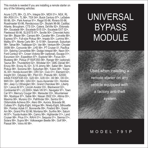
This module is needed if you are installing a remote starter on<br />
any of the following vehicles:<br />
Acura 3.2TL 98+, CL 97+, Integra 00+, MDX 01+, NSX, RL<br />
98+,RSX 01+, TL 98+, TSX 04+; Buick Century 97+, LeSabre<br />
90-96, 00+, Park Avenue 91+, Regal 93-96, Riviera 93-96,<br />
Roadmaster 93-96, Rendezvous 02+, Skylark 96-98; Cadillac<br />
Allante, Brougham, CTS 03+, Catera, DeVille 92+, Eldorado<br />
89+, Escalade 99+, Escalade EVS 03+, Escalade EXT 02+,<br />
Fleetwood 90-96, SLS/STS 97+, Seville 90+; Chevrolet Astro<br />
Van 98+, Blazer 98+, Camaro 86+, Cavalier 96+, Corvette 88+,<br />
Express 97+, Full-size Pickup 98+, Impala 00+, Lumina 96+,<br />
Malibu 97+, Monte Carlo 96+, S-10 98+, Savannah, Suburban<br />
98+, Tahoe 98+, Trailblazer 02+, Van 98+, Venture 99+; Chrysler<br />
300M 99+, Concorde 98+, LHS 99+, PT Cruiser 01, Pacifica<br />
03+, Sebring Convertible 98+; Dodge Intrepid 98+, Neon 00+;<br />
Ford Contour 97+, Crown Victoria 98+ (optional), Escape 01+,<br />
Excursion 00+, Expedition 97+, Explorer 98+, Focus 00+,<br />
Mustang 98+, Pickup (F150/F250) 98+, Ranger 99+ (optional);<br />
Taurus 96+, Thunderbird 02+, Windstar 00+; GMC Denali 99+,<br />
Envoy 99+, Envoy XL 02+, S-15 Jimmy 98+, Safari 98+, Sierra<br />
Pickup 98+, Sonoma 98+, Suburban 98+, Yukon 98+, Yukon<br />
XL 00+; Honda Accord 98+, CRV 02+, Civic 01+, Element 02+,<br />
Insight 00+, Odyssey 98+, Pilot 03+, Prelude 98+, S2000;<br />
Infiniti FX35/FX45 03+, G20 00+, G35 03+, I30 98+, I35 03+,<br />
M45 03+, Q45 98+, QX4 00+; Isuzu Ascender 03+, Hombre<br />
98+; Jeep CJ (Wrangler) 99+, Grand Cherokee 99+, Liberty<br />
02+; Lexus All 97+; Lincoln Aviator 03+, Blackwood 02+,<br />
Continental 97+, LS 2000+; Mark VIII 97+, Navigator 97+, Town<br />
Car 97+; Mercury Cougar 99+, Marauder 03+, Mountaineer<br />
98+, Mystique 97+, Sable 96+; Nissan 350Z 03+, Altima 00+,<br />
Maxima 98+, Murano 03+, Pathfinder 99+, Sentra 00+;<br />
Oldsmobile Achieva 95+, Alero 99+, Aurora, Bravada 98,<br />
Cutlass 97+, Eighty-Eight, Intrigue 98+, Ninety-Eight, Silhouette<br />
99+; Pontiac Aztek 01, Bonneville 89+, Firebird 88+, Grand<br />
Am 96+, Grand Prix 92-96; Montana 99+, Sunfire 96+; Saturn<br />
All 97+; Toyota Avalon 98+, Camry 98+, Highlander 01+, Land<br />
Cruiser 98+, Prius 01+, RAV4 01+, Sequoia 01+, Sienna 01+,<br />
Solara 99+, Supra 98+; Volkswagen Beetle 98+, Golf 98+,<br />
Passat 98+, Volvo All 98+.<br />
<strong>UNIVERSAL</strong><br />
<strong>BYPASS</strong><br />
<strong>MODULE</strong><br />
Used when installing a<br />
remote starter on any<br />
vehicle equipped with<br />
a factory anti-theft<br />
system.<br />
MODEL 791P
791 <strong>UNIVERSAL</strong> <strong>BYPASS</strong> <strong>MODULE</strong><br />
The Model 791 interface module is used when<br />
installing remote start products in any vehicle equipped<br />
with an anti-theft system including BMW, Audi, Volvo<br />
and Mercedes. The Ford PATS, GMs PK3, VATS,<br />
Passlock I, Passlock II or any other transponder<br />
systems. This model allows easy interfacing while<br />
maintaining the OEM system’s integrity. The Model<br />
791 has no affect on factory anti-theft system when<br />
the remote start is not in use. The factory anti-theft<br />
system remains fully functional.<br />
BEFORE YOU BEGIN<br />
Refer to your system’s instruction manual, and<br />
our website at www.bulldogsecurity.com, to<br />
determine what type of anti-theft system your<br />
vehicle is equipped with.<br />
It will be necessary to open the 791 Module to remove<br />
the wiring harness before installation. To do so, simply<br />
insert a straight shank screwdriver into the two wide<br />
slot holes in the bottom of the module. Plug the wiring<br />
harness into the module. NOTE: If you are using<br />
the 791 Module as a transponder bypass you<br />
must insert a spare ignition key inside the black<br />
ribbon coil (as illustrated on page 9) then snap<br />
both halves of the module back together. This<br />
key must be a key that starts the vehicle.<br />
WARRANTY VALIDATION<br />
PLEASE FILL OUT THIS FORM AND MAIL IT<br />
IN TO REGISTER YOUR WARRANTY<br />
Your Name ________________________<br />
Address __________________________<br />
_________________________________<br />
Email Address _____________________<br />
Dealer Name ______________________<br />
Address __________________________<br />
_________________________________<br />
Date of Purchase ____/____/____<br />
Model #791<br />
Make/Model of Car __________________<br />
Year of Car _____<br />
V.I.N. # __________________________<br />
Final Quality Check By _______________<br />
Mail to: JBS Technologies<br />
225 Technology Way<br />
Steubenville, Ohio 43952<br />
2 11
PIN OUT AND WIRE COLORS<br />
Pin<br />
Color Function<br />
PASSKEY (VATS) INSTALLATION (GM<br />
only)<br />
#1<br />
#2<br />
Violet<br />
Blue<br />
Bulb Check<br />
Ignition Neg. Trip<br />
This FUEL SYSTEM shutdown anti-theft system is<br />
based on a pellet (resistor) built into the steel shaft<br />
of the ignition key. When the key is inserted into the<br />
ignition switch, the VATS (vehicle anti-theft system)<br />
#3 GreenNot Used<br />
computer reads the value of the resistor to make<br />
sure that it matches the programmed code and then<br />
MODEL<br />
#4 Yellow/Black Crank Wire<br />
turns on the fuel system so the vehicle can be started.<br />
791<br />
1. Locate two (2) wires in an ORANGE (or<br />
#5 Yellow Bypass Output<br />
sometimes BLACK) vinyl tube coming down<br />
#6 White Ignition Pos. In<br />
from the ignition switch. This tube will<br />
contain two (2) WHITE 22 ga. wires or one<br />
#7 Orange Ground<br />
WHITE and one PURPLE wire.<br />
2. Connect the YELLOW wire from the 791<br />
#8 Red Power<br />
bypass to the WHITE wire in the VATS<br />
tube that shows voltage when the key is<br />
Plus 2-PIN:<br />
TRANSPONDER LOOP<br />
turned to the ON or RUN position.<br />
3. Connect the ORANGE wire securely to the<br />
other WHITE or PURPLE wire that shows<br />
ground with the key in the on or run position.<br />
ERASING MEMORY<br />
4. Connect the RED wire from the 791 bypass<br />
to a constant +12 V supply.<br />
5. Connect the WHITE wire from the 791<br />
To Erase the Memory<br />
Power up the bypass module then unplug the eight<br />
bypass to the vehicle ignition wire or the<br />
large WHITE wire on the remote starter<br />
wire harness from the unit. Attach the BLUE wire<br />
connected to the PINK ignition wire on the<br />
from the eight wire harness to ground and plug the vehicle.<br />
eight wire harness back into the bypass module. 6. Connect the BLUE wire to the center WHITE<br />
When the RED light illuminates, unplug the eight wire wire on remote starter modules with an<br />
harness and disconnect the BLUE wire from ground. external relay harness or the WHITE wire<br />
The bypass module is now ready to learn a new<br />
labeled “ignition negative” or the YELLOW<br />
code.<br />
wire and sometimes the YELLOW WITH<br />
BLACK STRIPE wire marked “security<br />
bypass out”.<br />
7. Attach the YELLOW WITH BLACK STRIPE<br />
wire to the large YELLOW WITH BLACK<br />
STRIPE wire on the remote starter that ...........<br />
is connected to the starter/crank wire on .....the<br />
10 3
PASSKEY (VATS) INSTALLATION<br />
(GM only. cont.)<br />
STRIPE wire on the remote starter that ............<br />
is connected to the starter/crank wire on .....the<br />
ignition switch harness.<br />
8. The PURPLE and the GREEN wires are not<br />
used and should be taped up.<br />
9. Put the key in the ignition switch and start ..the<br />
vehicle with the key.<br />
10. Wait until the L.E.D. light on the 791 goes<br />
out. (See page 9 for LED placement.)<br />
11. Turn off the vehicle the system has learned<br />
the resistor value.<br />
NOTE: If the light does not illuminate on the 791<br />
when you first plug it in, you need to erase the<br />
memory. See page 10.<br />
Never cut, or probe into a small yellow tube as<br />
Ignition<br />
Switch<br />
1<br />
These wires will be<br />
very small in<br />
diameter.<br />
White or (Purple)<br />
White<br />
VATS<br />
2<br />
Yellow<br />
Orange<br />
MODEL 791<br />
NOTE: Do not plug the WHITE loop connector into<br />
the module unless your vehicle is equipped with<br />
a transponder system.<br />
TRANSPONDER INSTALLATION<br />
Ford, Chrysler, all imports and some GMs<br />
labeled “ignition negative” or the YELLOW<br />
wire and sometimes the YELLOW WITH<br />
BLACK STRIPE wire marked “security<br />
bypass out”.<br />
5. Attach the ORANGE wire to ground.<br />
All other wires on the module are not<br />
used. Tape the ends.<br />
6. Plug the loop wire into the white plug inside<br />
the module.<br />
7. When bypassing GMs transponder<br />
(PK3), attach the RED wire not to +12v<br />
constant, but to the heavy gauge<br />
YELLOW WITH BLACK STRIPE wire<br />
from your remote starter that is<br />
connected to the starter/crank wire<br />
on the vehicle.<br />
Red L.E.D.<br />
8 Position Harness<br />
Connector<br />
Place the transponder loops<br />
around the ignition switch as close<br />
to the pick up coil or key hole end<br />
as possible.<br />
Extra ignition key.<br />
Place inside the black<br />
loop.<br />
Once key is in place<br />
and transponder loop<br />
is plugged in, snap<br />
both halves of Module<br />
791 together.<br />
Transponder Loop Plug<br />
Secure the loop with a<br />
small wire tie around the<br />
cylinder.<br />
Ignition Switch<br />
4 9
PASSLOCK II INSTALLATION<br />
(GM only)<br />
PASSLOCK I INSTALLATION<br />
(GM only)<br />
10. .........Wait until the L.E.D. light on the 791 goes This FUEL SYSTEM shutdown anti-theft system is<br />
out. (See page 9 for LED placement.)<br />
based on a resistor built into the ignition switch. The<br />
11. Turn off the vehicle, the system has learned system is recognized by a security light on the<br />
the resistor value.<br />
dashboard cluster.<br />
1. Locate the harness coming from the ignition<br />
NOTE: If the light does not illuminate on the 791<br />
switch inside, find the three small wires<br />
when you first plug it in, you need to erase the<br />
YELLOW, BLACK and WHITE or (1)<br />
memory. See page 10.<br />
BLACK WITH WHITE STRIPE wire and<br />
Red/White or (White)<br />
(2) BLACK wires.<br />
Ignition<br />
1 Orange/Black or (Black)<br />
To instrument<br />
2<br />
Panel Cluster 2. If your vehicle has the BLACK WITH<br />
Switch Yellow<br />
3<br />
WHITE STRIPE wire and two (2) BLACK<br />
These wires will be very<br />
wires, you will need to test the two (2)<br />
small in diameter.<br />
BLACK wires WITH THE IGNITION KEY IN<br />
THE ON OR RUN POSITION. Test both of<br />
MODEL 791<br />
these wires, one will show ground and the<br />
other will show positive.<br />
NOTE: Do not plug the WHITE loop connector into 3. Attach the YELLOW wire from the 791<br />
the module unless your vehicle is equipped with a<br />
bypass to the Passlock wire that shows a<br />
transponder system.<br />
positive.<br />
4. Attach the ORANGE wire from the 791<br />
TRANSPONDER INSTALLATION bypass to the wire that shows a ground.<br />
Ford, Chrysler, all imports and some GMs<br />
5. Attach the RED wire to a constant +12V<br />
supply.<br />
1. You must have a spare transponder key<br />
6. Attach the VIOLET wire to the bulb check<br />
wire. A 22 ga. BLACK wire in slot “D” or<br />
that will start the vehicle. You will need<br />
“E” coming from the ignition switch on the<br />
to insert this spare key inside the 791<br />
left hand side of the steering column located<br />
module.<br />
along with the heavy RED power wires in<br />
2. The wiring loop needs to be positioned<br />
the ignition switch harness. This wire will<br />
around the ignition switch. Place the<br />
test negative only during cranking.<br />
transponder loop around the ignition switch 7. Connect the BLUE wire to the center WHITE<br />
and as close to the key hole as possible.<br />
wire on remote starter modules with an<br />
3. Connect the RED wire from the module to<br />
external relay harness or the WHITE wire<br />
a constant +12v supply.<br />
labeled “ignition negative” or the YELLOW<br />
4. Connect the BLUE wire to the center WHITE<br />
wire and sometimes the YELLOW WITH<br />
wire on remote starter modules with an<br />
BLACK STRIPE wire marked “security<br />
external relay harness or the WHITE wire<br />
bypass out”.<br />
8 5<br />
Orange<br />
Yellow
PASSLOCK I INSTALLATION<br />
(GM only)<br />
PASSLOCK II INSTALLATION<br />
(GM only)<br />
8. Attach the YELLOW WITH BLACK STRIPE<br />
wire to the large YELLOW WITH BLACK<br />
1. Locate the wire harness coming from the<br />
ignition switch. Inside, find .........three (3) small<br />
STRIPE wire on the remote starter that is<br />
gauge wires, a RED WITH WHITE STRIPE<br />
connected to the starter/crank wire on the<br />
wire, an ORANGE WITH BLACK STRIPE<br />
ignition switch harness.<br />
wire or a BLACK wire, and a YELLOW wire<br />
9. Attach the WHITE wire from the bypass<br />
on trucks, vans and SUVs. On cars find a<br />
module to the large WHITE wire on the<br />
remote starter that is connected to the<br />
BLACK wire, a YELLOW wire and a WHITE<br />
PINK ignition wire on the ignition switch<br />
wire.<br />
harness.<br />
2. Attach the YELLOW wire to the Passlock<br />
10. Put the key in the ignition and start the<br />
YELLOW wire.<br />
vehicle.<br />
3. Attach the RED wire to a constant +12V<br />
11. Wait until the L.E.D. light on the 791 goes supply.<br />
out. (See page 9 for LED placement.)<br />
4. Connect the ORANGE wire to the ORANGE<br />
12. Turn off the vehicle, the system has learned<br />
WITH BLACK STRIPE wire or BLACK<br />
the resistor value.<br />
Passlock ground wire.<br />
13. The GREEN wire is not used.<br />
5. Connect the BLUE wire to the center WHITE<br />
NOTE: If the light does not illuminate on the 791<br />
wire on remote starter modules with an<br />
when you first plug it in, you need to erase the<br />
memory. See page 10.<br />
external relay harness or the WHITE wire<br />
labeled “ignition negative” or the YELLOW<br />
White or (Black/White)<br />
wire and sometimes the YELLOW WITH<br />
Ignition<br />
1 Black<br />
To instrument<br />
2<br />
Panel Cluster<br />
Switch Yellow or (Black)<br />
BLACK STRIPE wire marked “security<br />
3<br />
bypass out”.<br />
These wires will be very<br />
6. Attach the WHITE wire to large WHITE<br />
small in diameter.<br />
ignition wire on the remote starter connected<br />
MODEL 791<br />
to the PINK wire on the ignition harness.<br />
7. Attach the YELLOW WITH BLACK STRIPE<br />
wire to the large YELLOW WITH BLACK<br />
NOTE: Do not plug the WHITE loop connector<br />
STRIPE wire on the remote starter that ...........<br />
into the module unless your vehicle is equipped<br />
is connected to the starter/crank wire on .....the<br />
with a transponder system.<br />
ignition switch harness.<br />
8. The PURPLE and the GREEN wires are not<br />
used. Tape these wires up and do not use.<br />
9. Put the key in the ignition switch and start<br />
the vehicle.<br />
6 7<br />
Orange<br />
Yellow