DA 516 Submittal F315 - Flow Design Inc.
DA 516 Submittal F315 - Flow Design Inc.
DA 516 Submittal F315 - Flow Design Inc.

You also want an ePaper? Increase the reach of your titles
YUMPU automatically turns print PDFs into web optimized ePapers that Google loves.
F L O W D E S I G N I N C<br />
<strong>DA</strong> <strong>516</strong><br />
Adjustable Differential Pressure Controller<br />
Form No.: <strong>F315</strong>.0<br />
Date: 1.08<br />
Supersedes:<br />
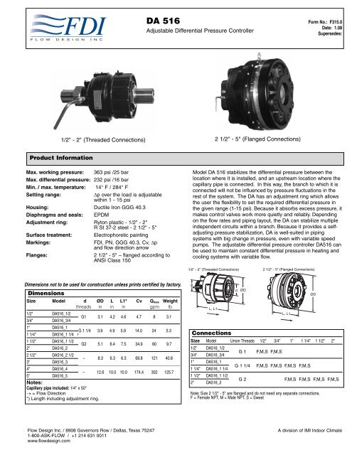
1/2" - 2" (Threaded Connections) 2 1/2" - 5" (Flanged Connections)<br />
Product Information<br />
Max. working pressure: 363 psi /25 bar<br />
Max. differential pressure: 232 psi /16 bar<br />
Min. / max. temperature: 14° F / 284° F<br />
Setting range:<br />
∆p over the load is adjustable<br />
within 1 - 15 psi<br />
Housing: Ductile Iron GGG 40.3<br />
Diaphragms and seals: EPDM<br />
Adjustment ring: Ryton plastic - 1/2" - 2"<br />
R St 37-2 steel - 2 1/2" - 5"<br />
Surface treatment: Electrophoretic painting<br />
Markings:<br />
FDI, PN, GGG 40.3, Cv, ∆p<br />
and flow direction arrow<br />
Flanges:<br />
2 1/2" - 5" – flanged according to<br />
ANSI Class 150<br />
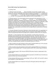
Model <strong>DA</strong> <strong>516</strong> stabilizes the differential pressure between the<br />
location where it is installed, and an upstream location where the<br />
capillary pipe is connected. In this way, the branch to which it is<br />
connected will not be influenced by pressure fluctuations in the<br />
rest of the system. The <strong>DA</strong> has an adjustment ring which allows<br />
the user the flexibility to set the required differential pressure in<br />
the given range (1-15 psi). Because it absorbs excess pressure, it<br />
makes control valves work more quietly and reliably. Depending<br />
on the flow rates and piping layout, the <strong>DA</strong> can stabilize multiple<br />
independent circuits within a branch. Because it provides a selfadjusting<br />
pressure stabilization, <strong>DA</strong> is well-suited in piping<br />
systems with big change in pressure, even with variable speed<br />
pumps. The adjustable differential pressure controller <strong>DA</strong><strong>516</strong> can<br />
be used to maintain constant differential pressure in heating and<br />
cooling systems with variable flow.<br />
1/2” - 2” Threaded<br />
1/2" - 2" (Threaded Connections) 2 1/2" 2 1/2” - 5" -(Flanged 5” Flanged Connections)<br />
Dimensions not to be used for construction unless prints certified by factory.<br />
Dimensions<br />
Size Model d ØD L L1* Cv Q max Weight<br />
threads in in in gpm lb<br />
1/2" <strong>DA</strong><strong>516</strong>_1/2<br />
G1 3.1 4.2 4.6 4.7 8 3.1<br />
3/4" <strong>DA</strong><strong>516</strong>_3/4 G1 3.1 4.2 4.6 4.7 8 3.1<br />
1" <strong>DA</strong><strong>516</strong>_1<br />
G 1 1/4 3.9 4.9 5.9 14.0 24 5.3<br />
1 1/4" <strong>DA</strong><strong>516</strong>_1 1/4 G 1 1/4 3.9 4.9 5.9 14.0 24 5.3<br />
1 1/2" <strong>DA</strong><strong>516</strong>_1 1/2<br />
G2 5.1 6.4 7.5 34.9 60 9.7<br />
2" <strong>DA</strong><strong>516</strong>_2 G2 5.1 6.4 7.5 34.9 60 9.7<br />
2 1/2" <strong>DA</strong><strong>516</strong>_2 1/2<br />
3" <strong>DA</strong><strong>516</strong>_3<br />
– 8.3 6.3 6.3 69.8 121 40.8<br />
Notes:<br />
4" <strong>DA</strong><strong>516</strong>_4<br />
5" <strong>DA</strong><strong>516</strong>_5<br />
– 12.6 10.0 10.0 174.4 302 125.7<br />
Capillary pipe included: 1/4" x 50"<br />
→ = <strong>Flow</strong> Direction<br />
*) Length including adjustment ring.<br />
d<br />
L, L1<br />
Connections<br />
Size Model Union Threads 1/2" 3/4" 1" 1 1/4" 1 1/2" 2"<br />
1/2" <strong>DA</strong><strong>516</strong>_1/2<br />
G 1 F,M,S F,M,S<br />
3/4" <strong>DA</strong><strong>516</strong>_3/4<br />
1" <strong>DA</strong><strong>516</strong>_1<br />
1 1/4" <strong>DA</strong><strong>516</strong>_1 1/4<br />
1 1/2" <strong>DA</strong><strong>516</strong>_1 1/2<br />
2" <strong>DA</strong><strong>516</strong>_2<br />
d<br />
ØD<br />
G 1 1/4<br />
G 2<br />
L, L1<br />
F,M,S F,M,S F,M,S F,M,S<br />
ØD<br />
F,M,S F,M,S F,M,S F,M,S<br />
Note: Size 2 1/2" - 5" are flanged and do not need any separate connections.<br />
F = Female NPT, M = Male NPT, S = Sweat<br />
<strong>Flow</strong> <strong>Design</strong> <strong>Inc</strong>. / 8908 Governors Row / Dallas, Texas 75247<br />
1-800-ASK-FLOW / +1 214 631 0011<br />
www.flowdesign.com<br />
A division of IMI Indoor Climate
F L O W D E S I G N I N C<br />
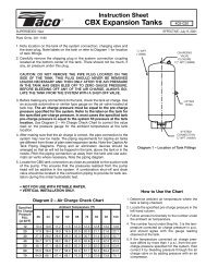
Operating Function<br />
Operating Function<br />
The pressure before the load (object across which you want to stabilize pressure) acts<br />
through an external capillary pipe (∆p+) on the plus side of the diaphragm (1) and<br />
attempts to close the valve.<br />
The pressure after the load acts via an internal capillary pipe in the valve body and<br />
attempts, together with the spring (3) force, to open the valve. In this way, the<br />
differential pressure over the load is kept constant on the set value.<br />
The spring force can be adjusted by turning the adjustment ring (5). Adjustment can be<br />
fixed by tightening the fixing screw (4).<br />
(1) Diaphragm (2) Venting Screws (3) Spring<br />
(4) Fixing Screw (5) Adjustment Ring<br />
∆p+<br />
1 2 3 4 5<br />
∆p-<br />
R1/4<br />
Installation<br />
Note! <strong>DA</strong> <strong>516</strong> valve closes at increasing<br />
differential pressure. Therefore, it is not<br />
recommended to install the <strong>DA</strong> <strong>516</strong> valves in the<br />
bypass line of constant flow systems. It is not<br />
allowed to disassemble the valve body. By<br />
incorrect handling, the controller may not<br />
∆p+<br />
work properly and safety problems may<br />
occur.<br />
Turn the adjustment ring (5) clock-wise until<br />
stop and the nut (7) on the outlet side will<br />
be accessible.<br />
The <strong>DA</strong> <strong>516</strong> must be installed downstream of<br />
the load for which the pressure is being<br />
controlled. <strong>Flow</strong> direction is shown by arrow (11)<br />
on the valve's identification plate (10). The best<br />
position is horizontal with the venting screws (2)<br />
pointing upwards. Installation of a strainer (<strong>Flow</strong><br />
<strong>Design</strong> model YC) is recommended upstream of the<br />
valve. Connect capillary pipe (∆p+), to the pipeline<br />
upstream of the load. In case of a horizontal pipeline<br />
connect the capillary pipe laterally to prevent air and<br />
dirt from entering. When filling, vent the body by using<br />
the venting screws (2). When soldering the valve must<br />
be protected from too high temperature. This typically<br />
means that soldering should be carried out by<br />
slipping union nut and tail piece onto the pipe<br />
separate from the valve, soldering the tailpiece in<br />
place, and installing the valve with its gaskets<br />
between the tailpieces after they have cooled.<br />
Capillary pipe<br />
Before taking into operation, the capillary pipe must<br />
be installed. One end of the capillary pipe goes into<br />
the <strong>DA</strong> <strong>516</strong> and the other end of the capillary pipe is<br />
connected to the strainer YC (through the provided<br />
1/4" NPT fitting connection).<br />
11<br />
10<br />
Figure 3 b: Two Water 7<br />
9 8 Loops with TBV-Cs, <strong>DA</strong> <strong>516</strong> and YC<br />
YC<br />
<strong>DA</strong> <strong>516</strong><br />
2<br />
Figure 3<br />
UB<br />
∆p+<br />
∆p+<br />
5<br />
<strong>DA</strong> <strong>516</strong><br />
<strong>DA</strong> <strong>516</strong><br />
YC<br />
M<br />
M<br />
UP<br />
Figure 1<br />
Figure 2<br />
TBV-C
<strong>DA</strong> <strong>516</strong><br />
Adjustable Differential Presssure Controller<br />
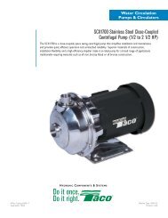
Setting<br />
The differential pressure can be adjusted by turning the adjustment ring. For 2" and smaller valves, the adjustment ring has a marking<br />
for ∆p for each turn. The preset value can be secured by attaching a wire through the holes.<br />
Pressure Adjustment<br />
Differential pressure adjustment for <strong>DA</strong> <strong>516</strong>, ½” to 2”<br />
1. Unscrew the fixing screw (4) with a 2mm Allen key on the setting wheel (1).<br />
2. Turn the setting wheel clockwise to increase the differential pressure and<br />
vice versa.<br />
3. On the setting wheel, there is a mark which shows how the ∆p changes at one<br />
turn of the setting wheel.<br />
4. The pressure can also be measured through pressure gauges on the pipeline<br />
and adjusted through the setting wheel.<br />
5. After the required differential pressure ∆p is reached, tighten the fixing screw<br />
on the setting wheel.<br />
6. It is also possible to secure the setting with the leaden seal by using the holes<br />
on the body and the setting wheel (1).<br />
1<br />
4<br />
∆p<br />
∆p<br />
Differential pressure adjustment for <strong>DA</strong> <strong>516</strong>, 2 ½” and above<br />
1. The principle of adjustment for the <strong>DA</strong> <strong>516</strong>, size 2 1/2” and above is the same<br />
as size 2“ and below, except there is no mark which shows how the ∆p<br />
changes at one turn of the setting wheel. Also there is no fixing screw and no<br />
leaden seal.<br />
∆p =min<br />
2. The setting wheel (10) moves indirectly by the middle nut (11), which can be<br />
turned by the tool provided with the <strong>DA</strong> <strong>516</strong> in the package.<br />
∆p<br />
3. The pressure can be set by reading the pressure gauges on the pipeline and<br />
adjusting the middle nut according to the requirements.<br />
11 10
<strong>DA</strong> <strong>516</strong><br />
Adjustable Differential Presssure Controller<br />
F L O W D E S I G N I N C<br />
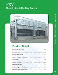
Sizing<br />
1. Select the smallest size for the designed flow according to the diagram.<br />
2. Check that the available ∆p is bigger than the pressure drop of the <strong>DA</strong> <strong>516</strong> at the designed flow.<br />
The pressure drop can be found in the diagram or calculated by the formula:<br />
Differential Pressure (psi)<br />
3<br />
2<br />
Size Size Size Size Size<br />
1/2” / 3/4” 1” / 1 1/4” 1 1/2” / 2” 2 1/2” / 3” 4” / 5”<br />
1<br />
0.5<br />
0.25<br />
0.2<br />
1.5 2<br />
4 8 16 32 64 128 256 350<br />
Q (gpm)<br />
8908 Governors Row / Dallas, Texas 75247<br />
1-800-ASK-FLOW / +1 214 631 0011<br />
www.flowdesign.com