guide for multi-architecture live-virtual-constructive environment ...
guide for multi-architecture live-virtual-constructive environment ...
guide for multi-architecture live-virtual-constructive environment ...

Create successful ePaper yourself
Turn your PDF publications into a flip-book with our unique Google optimized e-Paper software.
Enclosure to: NSAD-L-2010-149<br />
JNC04<br />
NSAD-R-2010-044<br />
GUIDE FOR MULTI-ARCHITECTURE<br />
LIVE-VIRTUAL-CONSTRUCTIVE<br />
ENVIRONMENT ENGINEERING AND<br />
EXECUTION<br />
JUNE 2010<br />
NATIONAL SECURITY ANALYSIS DEPARTMENT<br />
THE JOHNS HOPKINS UNIVERSITY APPLIED PHYSICS LABORATORY<br />
Johns Hopkins Road, Laurel, Maryland 20723‐6099
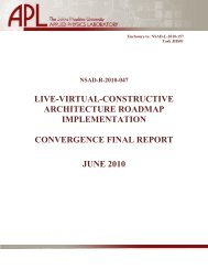
NSAD-R-2010-044<br />
Guide <strong>for</strong> Multi-Architecture<br />
Live-Virtual-Constructive<br />
Environment Engineering and Execution<br />
June 2010<br />
FOR:<br />
BY:<br />
Joint Training Integration and Evaluation Center<br />
1200 Research Parkway, Suite 300<br />
Orlando, FL 32826<br />
Johns Hopkins University - Applied Physics Laboratory<br />
11100 Johns Hopkins Road<br />
Laurel, MD 20723
Guide <strong>for</strong> Multi-Architecture Live-Virtual-Constructive Environment Engineering and Execution<br />
This page intentionally left blank.
Guide <strong>for</strong> Multi-Architecture Live-Virtual-Constructive Environment Engineering and Execution<br />
TABLE OF CONTENTS<br />
EXECUTIVE SUMMARY ...................................................................................................... ES-1<br />
1 INTRODUCTION ................................................................................................................. 1-1<br />
1.1 BACKGROUND ............................................................................................................. 1-1<br />
1.2 SCOPE ............................................................................................................................. 1-6<br />
1.3 DOCUMENT OVERVIEW............................................................................................. 1-6<br />
1.4 DEFINITIONS ................................................................................................................. 1-7<br />
2 MULTI-ARCHITECTURE ISSUES AND SOLUTIONS .................................................... 2-1<br />
2.1 STEP 1: DEFINE SIMULATION ENVIRONMENT OBJECTIVES ............................ 2-1<br />
2.1.1 Activity 1.1: Identify User/Sponsor Needs ............................................................. 2-1<br />
2.1.2 Activity 1.2: Develop Objectives ............................................................................ 2-1<br />
2.1.3 Activity 1.3: Conduct Initial Planning .................................................................... 2-1<br />
2.2 STEP 2: PERFORM CONCEPTUAL ANALYSIS ........................................................ 2-4<br />
2.2.1 Activity 2.1: Develop Scenario ............................................................................... 2-4<br />
2.2.2 Activity 2.2: Develop Conceptual Model ............................................................... 2-5<br />
2.2.3 Activity 2.3: Develop Simulation Environment Requirements .............................. 2-5<br />
2.3 STEP 3: DESIGN SIMULATION ENVIRONMENT .................................................... 2-7<br />
2.3.1 Activity 3.1: Select Member Applications .............................................................. 2-8<br />
2.3.2 Activity 3.2: Design Simulation Environment ...................................................... 2-10<br />
2.3.3 Activity 3.3: Design Member Applications .......................................................... 2-26<br />
2.3.4 Activity 3.4: Prepare Detailed Plan ...................................................................... 2-28<br />
2.4 STEP 4: DEVELOP SIMULATION ENVIRONMENT ............................................... 2-35<br />
2.4.1 Activity 4.1: Develop Simulation Data Exchange Model .................................... 2-35<br />
2.4.2 Activity 4.2: Establish Simulation Environment Agreements .............................. 2-40<br />
2.4.3 Activity 4.3: Implement Member Application Designs ........................................ 2-42<br />
2.4.4 Activity 4.4: Implement Simulation Environment Infrastructure ......................... 2-43<br />
2.5 STEP 5: INTEGRATE AND TEST SIMULATION ENVIRONMENT ...................... 2-46<br />
2.5.1 Activity 5.1: Plan Execution ................................................................................. 2-46<br />
2.5.2 Activity 5.2: Integrate Simulation Environment ................................................... 2-47<br />
2.5.3 Activity 5.3: Test Simulation Environment .......................................................... 2-48<br />
2.6 STEP 6: EXECUTE SIMULATION ............................................................................. 2-51<br />
2.6.1 Activity 6.1: Execute Simulation .......................................................................... 2-51<br />
2.6.2 Activity 6.2: Prepare Simulation Environment Outputs ....................................... 2-52<br />
2.7 STEP 7: ANALYZE DATA AND EVALUATE RESULTS ........................................ 2-53<br />
2.7.1 Activity 7.1: Analyze Data ................................................................................... 2-53<br />
2.7.2 Activity 7.2: Evaluate and Feedback Results ....................................................... 2-53<br />
APPENDIX A. REFERENCES AND BIBLIOGRAPHY ................................................... 1<br />
APPENDIX B. MAPPING OF ISSUES TO EXISTING ARCHITECTURES ................... 1<br />
Page i
Guide <strong>for</strong> Multi-Architecture Live-Virtual-Constructive Environment Engineering and Execution<br />
APPENDIX C. ABBREVIATIONS AND ACRONYMS ................................................... 1<br />
LIST OF FIGURES<br />
Figure 1-1. Gateway Configuration ........................................................................................ 1-2<br />
Figure 1-2. Middleware Configuration ................................................................................... 1-3<br />
Figure 1-3.<br />
Distributed Simulation Engineering and Execution Process (DSEEP), Top-Level<br />
Process Flow View .............................................................................................. 1-4<br />
Page ii
Guide <strong>for</strong> Multi-Architecture Live-Virtual-Constructive Environment Engineering and Execution<br />
EXECUTIVE SUMMARY<br />
Robust, well-defined systems engineering (SE) processes are a key element of any<br />
successful development project. In the distributed simulation community, there are several such<br />
processes in wide use today, each aligned with a specific simulation <strong>architecture</strong> such as<br />
Distributed Interactive Simulation (DIS), High Level Architecture (HLA), and Test and Training<br />
Enabling Architecture (TENA). However, there are an increasing number of distributed<br />
simulation applications within the Department of Defense (DoD) that require the selection of<br />
simulations whose external interfaces are aligned with more than one simulation <strong>architecture</strong>.<br />
This is what is known as a <strong>multi</strong>-<strong>architecture</strong> simulation <strong>environment</strong>.<br />
Many technical issues arise when <strong>multi</strong>-<strong>architecture</strong> simulation <strong>environment</strong>s are being<br />
developed and executed. These issues tend to increase program costs and can increase technical<br />
risk and impact schedules if not resolved adequately. The Live-Virtual-Constructive Architecture<br />
Roadmap (LVCAR) was initiated in 2007 to define the differences among the major simulation<br />
<strong>architecture</strong>s from technical, business, and standards perspectives and to develop a time-phased<br />
set of actions to improve interoperability within <strong>multi</strong>-<strong>architecture</strong> simulation <strong>environment</strong>s in<br />
the future.<br />
One of the barriers to interoperability identified in the LVCAR Phase I Report was driven<br />
by a community-wide recognition that when user communities, aligned with the different<br />
simulation <strong>architecture</strong>s, are brought together to develop a <strong>multi</strong>-<strong>architecture</strong> distributed<br />
simulation <strong>environment</strong>, the differences in the development processes native to each user<br />
community adversely affected the ability to collaborate effectively. To address this problem, a<br />
recommendation was made to establish a common cross-community SE process <strong>for</strong> the<br />
development and execution of <strong>multi</strong>-<strong>architecture</strong> simulation <strong>environment</strong>s. However, rather than<br />
develop an entirely new process, it was recognized that an existing process standard should be<br />
leveraged and extended to address <strong>multi</strong>-<strong>architecture</strong> concerns. The process framework that was<br />
chosen is an emerging Institute of Electrical and Electronics Engineers (IEEE) standard called<br />
the Distributed Simulation Engineering and Execution Process (DSEEP). The DSEEP tailors<br />
widely recognized and accepted SE practices to the modeling and simulation domain and, more<br />
specifically, to the development and execution of distributed simulation <strong>environment</strong>s. The<br />
strategy implemented in this case was to augment the major DSEEP steps and activities with the<br />
additional tasks that are needed to address the issues that are unique to (or at least exacerbated<br />
by) <strong>multi</strong>-<strong>architecture</strong> development. These tasks collectively define a “how to” <strong>guide</strong> <strong>for</strong><br />
developing and executing <strong>multi</strong>-<strong>architecture</strong> simulation <strong>environment</strong>s, based on recognized best<br />
practices.<br />
This document defines a total of 40 <strong>multi</strong>-<strong>architecture</strong> related issues, based on an<br />
extensive literature search. Each of these issues is aligned with the activity in the DSEEP <strong>for</strong><br />
which the issue first becomes relevant. Each issue comes with both a description and a<br />
Page ES-1
Guide <strong>for</strong> Multi-Architecture Live-Virtual-Constructive Environment Engineering and Execution<br />
recommended action(s) to best address the issue. A set of inputs, outcomes, and recommended<br />
tasks is also provided <strong>for</strong> each DSEEP activity to address the resolution of the <strong>multi</strong>-<strong>architecture</strong><br />
issues. This in<strong>for</strong>mation is provided as an overlay to corresponding in<strong>for</strong>mation already provided<br />
in the DSEEP document <strong>for</strong> single-<strong>architecture</strong> development.<br />
An appendix to this document identifies a tailoring of the guidance provided in the main<br />
document to individual <strong>architecture</strong> communities. For each of three major simulation<br />
<strong>architecture</strong>s, a mapping is provided to indicate the relevance of each Issue–Recommended<br />
Action pair to developers and users of that simulation <strong>architecture</strong>. Together with the guidance<br />
provided in the main text, it is believed that this document will provide the guidance needed to<br />
improve cross-community collaboration and thus reduce costs and technical risk in future <strong>multi</strong><strong>architecture</strong><br />
developments.<br />
Page ES-2
Guide <strong>for</strong> Multi-Architecture Live-Virtual-Constructive Environment Engineering and Execution<br />
1 INTRODUCTION<br />
1.1 BACKGROUND<br />
Modeling and simulation (M&S) has long been recognized as a critical technology <strong>for</strong><br />
managing the complexity associated with modern systems. In the defense industry, M&S is a key<br />
enabler of many core systems engineering functions. For instance, early in the systems<br />
acquisition process, relatively coarse, aggregate-level <strong>constructive</strong> models are generally used to<br />
identify capability gaps, define systems requirements, and examine/compare potential system<br />
solutions. As preferred concepts are identified, higher-fidelity models are used to evaluate<br />
alternative system designs and to support initial system development activities. As design and<br />
development continues, very high-fidelity models are used to support component-level design<br />
and development, as well as developmental test. Finally, combinations of <strong>virtual</strong> and<br />
<strong>constructive</strong> M&S assets are frequently used to support operational test and training<br />
requirements. Note that other industries (e.g., entertainment, medical, transportation) also make<br />
heavy use of M&S, although in somewhat different ways.<br />
The advent of modern networking technology and the development of supporting<br />
protocols and <strong>architecture</strong>s have led to widespread use of distributed simulation. The strategy<br />
behind distributed simulation is to use networks and support simulation services to link existing<br />
M&S assets into a single unified simulation <strong>environment</strong>. This approach provides several<br />
advantages as compared to development and maintenance of large monolithic stand-alone<br />
simulation systems. First, it allows each individual simulation application to be co-located with<br />
its resident subject matter expertise rather than having to develop and maintain a large standalone<br />
system in one location. In addition, it facilitates efficient use of past M&S investments, as<br />
new, very powerful simulation <strong>environment</strong>s can be quickly configured from existing M&S<br />
assets. Finally, it provides flexible mechanisms to integrate hardware and/or <strong>live</strong> assets into a<br />
unified <strong>environment</strong> <strong>for</strong> test or training, and it is much more scalable than stand-alone systems.<br />
There are also some disadvantages of distributed simulation. Many of the issues related to<br />
distributed simulation are related to interoperability concerns. Interoperability refers to the<br />
ability of disparate simulation systems and supporting utilities (e.g., viewers, loggers) to interact<br />
at runtime in a coherent fashion. There are many technical issues that affect interoperability, such<br />
as consistency of time advancement mechanisms, compatibility of supported services, data<br />
<strong>for</strong>mat compatibility, and even semantic mismatches <strong>for</strong> runtime data elements. The capabilities<br />
provided by today’s distributed simulation <strong>architecture</strong>s are designed to address such issues and<br />
allow coordinated runtime interaction among participating simulations. Examples of such<br />
<strong>architecture</strong>s include Distributed Interactive Simulation (DIS), the Test and Training Enabling<br />
Architecture (TENA), and the High Level Architecture (HLA).<br />
In some situations, sponsor requirements may necessitate the selection of simulations<br />
whose external interfaces are aligned with more than one simulation <strong>architecture</strong>. This is what is<br />
Page 1-1
Guide <strong>for</strong> Multi-Architecture Live-Virtual-Constructive Environment Engineering and Execution<br />
known as a <strong>multi</strong>-<strong>architecture</strong> simulation <strong>environment</strong>. There are many examples of such<br />
<strong>environment</strong>s within the Department of Defense (DoD) (see references <strong>for</strong> examples). When<br />
more than one simulation <strong>architecture</strong> must be used in the same <strong>environment</strong>, interoperability<br />
problems are compounded by the architectural differences. For instance, middleware<br />
incompatibilities, dissimilar metamodels <strong>for</strong> data exchange, and differences in the nature of the<br />
services that are provided by the <strong>architecture</strong>s must all be reconciled <strong>for</strong> such <strong>environment</strong>s to<br />
operate properly. Developers have devised many different workarounds <strong>for</strong> these types of<br />
interoperability problems over the years. One possible solution is to choose a single <strong>architecture</strong><br />
<strong>for</strong> the simulation <strong>environment</strong> and require all participants to modify the native interfaces of their<br />
simulations to con<strong>for</strong>m to it. While this solution is relatively straight<strong>for</strong>ward and easy to test, it is<br />
usually impractical (particularly in large applications) because of the high cost and schedule<br />
penalties incurred. Another approach is the use of gateways, which are independent software<br />
applications that translate between the protocols used by one simulation <strong>architecture</strong> to that of a<br />
different simulation <strong>architecture</strong> (see Figure 1-1). While effective, gateways represent another<br />
potential source of error (or failure) within the simulation <strong>environment</strong>, can introduce<br />
undesirable latencies into the system, and add to the complexity of simulation <strong>environment</strong><br />
testing. In addition, many gateways are legacy point solutions that provide support only <strong>for</strong> a<br />
very limited number of services and only <strong>for</strong> very specific versions of the supported simulation<br />
<strong>architecture</strong>s. Thus, it may be difficult to find a suitable gateway that fully supports the needs of<br />
a given application. For the relatively small number of general-purpose gateways that are<br />
configurable, the ef<strong>for</strong>t required to per<strong>for</strong>m the configuration function can be significant and can<br />
result in excessive consumption of project resources.<br />
DIS Enclave<br />
HLA Enclave<br />
TENA Enclave<br />
Sim1<br />
DIS Interface<br />
Sim2<br />
DIS Interface<br />
SimY<br />
DIS Interface<br />
Sim1<br />
HLA Interface<br />
Sim2<br />
HLA Interface<br />
SimX<br />
HLA Interface<br />
Sim1<br />
TENA Interface<br />
Sim2<br />
TENA Interface<br />
SimZ<br />
TENA Interface<br />
Gateway Gateway Gateway<br />
Network<br />
Figure 1-1. Gateway Configuration<br />
Page 1-2
Guide <strong>for</strong> Multi-Architecture Live-Virtual-Constructive Environment Engineering and Execution<br />
The use of middleware is a similar approach but provides the translation services in<br />
software directly coupled to the simulation instead of an independent application 1 (see Figure 1-<br />
2). While middleware approaches are also effective, they introduce many of the same technical<br />
issues that are associated with gateways (e.g., source of error, possible latency penalties). In<br />
general, all of these “solutions” have limitations and cost implications that increase technical,<br />
cost, and schedule risk <strong>for</strong> <strong>multi</strong>-<strong>architecture</strong> developments.<br />
DIS Enclave<br />
HLA Enclave<br />
TENA Enclave<br />
Sim1 Sim2 SimY<br />
Sim1 Sim2 SimX<br />
Sim1<br />
Sim2<br />
SimZ<br />
Middleware<br />
Middleware<br />
Middleware<br />
Middleware<br />
Middleware<br />
Middleware<br />
Middleware<br />
Middleware<br />
Middleware<br />
Network<br />
Figure 1-2. Middleware Configuration<br />
Because of perceived increases in the number of <strong>multi</strong>-<strong>architecture</strong> simulation events<br />
anticipated in the future, along with the associated increase in costs, the DoD sponsored an<br />
initiative to examine the differences among the major simulation <strong>architecture</strong>s from technical,<br />
business, and standards perspectives and to develop a time-phased set of actions to improve<br />
interoperability within <strong>multi</strong>-<strong>architecture</strong> simulation <strong>environment</strong>s in the future. This initiative<br />
was called the Live-Virtual-Constructive Architecture Roadmap (LVCAR). The first phase of<br />
this ef<strong>for</strong>t began in the spring of 2007 and continued <strong>for</strong> approximately 16 months. The result of<br />
this activity was a final report and supporting documentation that collectively totaled over 1000<br />
pages. The second phase of this initiative focused on the implementation of the recommended<br />
actions from this report.<br />
A key conclusion of the LVCAR ef<strong>for</strong>t was that migrating to a single distributed<br />
simulation <strong>architecture</strong> was impractical, and thus <strong>multi</strong>-<strong>architecture</strong> simulation <strong>environment</strong>s<br />
would remain the state of the practice <strong>for</strong> the <strong>for</strong>eseeable future. One of the key actions<br />
recommended in the LVCAR Phase I Report was the establishment of a common systems<br />
engineering process <strong>for</strong> the development and execution of <strong>multi</strong>-<strong>architecture</strong> simulation<br />
<strong>environment</strong>s. The widely reported issue in this case was that when user communities of<br />
different <strong>architecture</strong>s were brought together to develop a single <strong>multi</strong>-<strong>architecture</strong> distributed<br />
simulation <strong>environment</strong>, the differences in the development processes native to each user<br />
community were creating a persistent barrier to effective collaboration. That is, since these<br />
1 Note that this use of the term “middleware” is different in some user communities, who may use this term to refer<br />
to the infrastructure elements that provide distributed simulation services (e.g., the HLA Runtime Infrastructure<br />
[RTI]).<br />
Page 1-3
Guide <strong>for</strong> Multi-Architecture Live-Virtual-Constructive Environment Engineering and Execution<br />
communities had to work together toward common goals, differences in the practices and<br />
procedures these communities typically use to build new simulation <strong>environment</strong>s were leading<br />
to misunderstandings, misinterpretations, and general confusion among team members. This was<br />
impacting risk from many different perspectives.<br />
To develop the common systems engineering process, it was felt that leveraging and<br />
modifying/extending an existing systems engineering process standard was preferable to building<br />
an entirely new process description from scratch. Early in the project, the systems engineering<br />
process team considered several generalized and widely recognized systems and software<br />
standards (e.g., EIA-632, ISO/IEC 15288). However, the team decided that direct reuse of any<br />
process standard outside of the M&S domain would require a significant degree of tailoring,<br />
consuming resources that could be better applied in other ways. For that reason, the team<br />
selected an emerging Institute of Electrical and Electronics Engineers (IEEE) standard (IEEE<br />
1730) as the foundation <strong>for</strong> the desired process. The name of this standard is the Distributed<br />
Simulation Engineering and Execution Process (DSEEP).<br />
The DSEEP represents a tailoring of best practices in the systems and software<br />
engineering communities to the M&S domain. The DSEEP is simulation <strong>architecture</strong>-neutral, but<br />
it does contain annexes that map this <strong>architecture</strong>-neutral view to DIS, HLA, and TENA<br />
terminology. A top-level view of the DSEEP is provided in Figure 1-3.<br />
Define<br />
Simulation<br />
Environment<br />
Objectives<br />
Per<strong>for</strong>m<br />
Conceptual<br />
Analysis<br />
Design<br />
Simulation<br />
Environment<br />
Develop<br />
Simulation<br />
Environment<br />
Integrate<br />
and Test<br />
Simulation<br />
Environment<br />
Execute<br />
Simulation<br />
Analyze<br />
Data and<br />
Evaluate<br />
Results<br />
1<br />
2<br />
3<br />
4<br />
5<br />
6<br />
7<br />
Corrective Actions / Iterative Development<br />
Figure 1-3. Distributed Simulation Engineering and Execution Process (DSEEP), Top-<br />
Level Process Flow View<br />
A short description of each of these seven major steps follows:<br />
Step 1: Define Simulation Environment Objectives. The user, the sponsor, and the<br />
development/integration team define and agree on a set of objectives and document what must be<br />
accomplished to achieve those objectives.<br />
Step 2: Per<strong>for</strong>m Conceptual Analysis. The development team per<strong>for</strong>ms scenario<br />
development and conceptual modeling and develops the simulation <strong>environment</strong> requirements<br />
based upon the characteristics of the problem space.<br />
Page 1-4
Guide <strong>for</strong> Multi-Architecture Live-Virtual-Constructive Environment Engineering and Execution<br />
Step 3: Design Simulation Environment. Existing member applications that are suitable<br />
<strong>for</strong> reuse are identified, design activities <strong>for</strong> member application modifications and/or new<br />
member applications are per<strong>for</strong>med, required functionalities are allocated to the member<br />
applications, and a plan is developed <strong>for</strong> development and implementation of the simulation<br />
<strong>environment</strong>.<br />
Step 4: Develop Simulation Environment. The simulation data exchange model is<br />
developed, simulation <strong>environment</strong> agreements are established, and new member applications<br />
and/or modifications to existing member applications are implemented.<br />
Step 5: Integrate and Test Simulation Environment. All necessary integration activities<br />
are per<strong>for</strong>med, and testing is conducted to verify that interoperability requirements are being<br />
met.<br />
Step 6: Execute Simulation. The simulation <strong>environment</strong> is executed and the output data<br />
from the execution is pre-processed.<br />
Step 7: Analyze Data and Evaluate Results. The output data from the execution is<br />
analyzed and evaluated, and results are reported back to the user/sponsor.<br />
In the DSEEP document, each of these seven steps is further decomposed into a set of<br />
interrelated lower-level activities. Each activity is characterized according to a set of required<br />
activity inputs, one or more output products, and a list of recommended finer-grain tasks.<br />
Although these activity descriptions are identified in a logical sequence, the DSEEP emphasizes<br />
that iteration and concurrency are to be expected, not only across activities within a step but<br />
across steps as well.<br />
Although the DSEEP provides the guidance required to build and execute a distributed<br />
simulation <strong>environment</strong>, the implicit assumption within the DSEEP is that only a single<br />
simulation <strong>architecture</strong> is being used. The only acknowledgement that this assumption may be<br />
false is provided in the following paragraph from DSEEP Activity 3.2 (Design Simulation<br />
Environment):<br />
In some large simulation <strong>environment</strong>s, it is sometimes necessary to mix several<br />
simulation <strong>architecture</strong>s. This poses special challenges to the simulation <strong>environment</strong> design, as<br />
sophisticated mechanisms are sometimes needed to reconcile disparities in the <strong>architecture</strong><br />
interfaces. For instance, gateways or bridges to adjudicate between different on-the-wire<br />
protocols are generally a required element in the overall design, as well as mechanisms to<br />
address differences in simulation data exchange models. Such mechanisms are normally<br />
<strong>for</strong>malized as part of the member application agreements, which are discussed in Step 4.<br />
Clearly, additional guidance is necessary to support the development of <strong>multi</strong><strong>architecture</strong><br />
simulation <strong>environment</strong>s. However, the major steps and activities defined in the<br />
DSEEP are generally applicable to either single- or <strong>multi</strong>-<strong>architecture</strong> development. Thus, the<br />
Page 1-5
Guide <strong>for</strong> Multi-Architecture Live-Virtual-Constructive Environment Engineering and Execution<br />
DSEEP provides a viable framework <strong>for</strong> the development of the desired process, but it must be<br />
augmented with additional tasks as necessary to address the issues that are unique to (or at least<br />
exacerbated by) <strong>multi</strong>-<strong>architecture</strong> development. Such augmenting documentation is often<br />
referred to as an overlay. The tasks in this overlay collectively define a “how to” <strong>guide</strong> <strong>for</strong><br />
developing and executing <strong>multi</strong>-<strong>architecture</strong> simulation <strong>environment</strong>s, based on perceived best<br />
practices <strong>for</strong> issue resolution.<br />
The remainder of this first section describes the organization of and the associated<br />
constraints upon the overlay specification. This is critical to understanding the technical<br />
description of the overlay as described in Section 0.<br />
1.2 SCOPE<br />
This document is intended <strong>for</strong> users and developers of <strong>multi</strong>-<strong>architecture</strong> simulation<br />
<strong>environment</strong>s. It describes a comprehensive set of technical issues that are either unique to <strong>multi</strong><strong>architecture</strong><br />
development or are more difficult to resolve in <strong>multi</strong>-<strong>architecture</strong> simulation<br />
<strong>environment</strong>s. The solution(s) provided <strong>for</strong> each issue are focused on <strong>multi</strong>-<strong>architecture</strong><br />
developments but may have applicability to single-<strong>architecture</strong> development as well.<br />
This document is intended as a companion <strong>guide</strong> to the DSEEP. The simulation<br />
<strong>environment</strong> user/developer should assume that the guidance provided by the DSEEP is<br />
applicable to both single- and <strong>multi</strong>-<strong>architecture</strong> developments but that this document provides<br />
the additional guidance needed to address the special concerns of this class of the <strong>multi</strong><strong>architecture</strong><br />
user/developer.<br />
1.3 DOCUMENT OVERVIEW<br />
This document is organized as an overlay to the DSEEP. Each subsection begins with a<br />
short description of the DSEEP activity. Next, the <strong>multi</strong>-<strong>architecture</strong> technical issue(s) that are<br />
relevant to that DSEEP activity are listed and described. 2 After the statement of each issue, the<br />
recommended action(s) to address that issue are presented. Finally, the recommended action(s)<br />
<strong>for</strong> the issue are translated into an appropriate set of inputs, outcomes, and recommended tasks to<br />
augment corresponding DSEEP inputs/outcomes/tasks <strong>for</strong> that activity. This structure is repeated<br />
<strong>for</strong> all of the activities defined in the DSEEP document.<br />
Note that some DSEEP activities do not have any technical issues associated with them.<br />
This indicates that the existing DSEEP activity description applies equally well to either singleor<br />
<strong>multi</strong>-<strong>architecture</strong> <strong>environment</strong>s and that there are no additional <strong>multi</strong>-<strong>architecture</strong>-specific<br />
2 Some issues impact <strong>multi</strong>ple DSEEP activities. Rather than repeating the issue <strong>multi</strong>ple times, it is elaborated at<br />
the first affected activity.<br />
Page 1-6
Guide <strong>for</strong> Multi-Architecture Live-Virtual-Constructive Environment Engineering and Execution<br />
inputs, outcomes, or recommended tasks <strong>for</strong> that activity. This situation mainly occurs either<br />
early or late in the overall process.<br />
1.4 DEFINITIONS<br />
Conceptual Model: An abstraction of what is intended to be represented within a simulation<br />
<strong>environment</strong>, which serves as a frame of reference <strong>for</strong> communicating simulation-neutral views<br />
of important entities and their key actions and interactions. The conceptual model describes what<br />
the simulation <strong>environment</strong> will represent, the assumptions limiting those representations, and<br />
other capabilities needed to satisfy the user’s requirements. Conceptual models are bridges<br />
between the real world, requirements, and simulation design.<br />
Member Application: An application that is serving some defined role within a simulation<br />
<strong>environment</strong>. This can include <strong>live</strong>, <strong>virtual</strong>, or <strong>constructive</strong> (LVC) simulation assets or can be<br />
supporting utility programs such as data loggers or visualization tools.<br />
Objective: The desired goals and results of the activity to be conducted in the distributed<br />
simulation <strong>environment</strong> expressed in terms relevant to the organization(s) involved.<br />
Requirement: A statement identifying an unambiguous and testable characteristic, constraint,<br />
process, or product of an intended simulation <strong>environment</strong>.<br />
Simulation Environment: A named set of member applications along with a common<br />
simulation data exchange model and set of agreements that are used as a whole to achieve some<br />
specific objective.<br />
Live Simulation: A simulation involving real people operating real systems.<br />
Virtual Simulation: A simulation involving real people operating simulated systems. Virtual<br />
simulations inject human-in-the-loop (HITL) in a central role by exercising motor control skills<br />
(e.g., flying an airplane), decision skills (e.g., committing fire control resources to action), or<br />
communication skills (e.g., as members of a command, control, communications, computers, and<br />
intelligence [C4I] team).<br />
Constructive Simulation: Models and simulations that involve simulated people operating<br />
simulated systems. Real people stimulate (make inputs) to such simulations but are not involved<br />
in determining the outcomes.<br />
Page 1-7
Guide <strong>for</strong> Multi-Architecture Live-Virtual-Constructive Environment Engineering and Execution<br />
This page intentionally left blank.<br />
Page 1-8
Guide <strong>for</strong> Multi-Architecture Live-Virtual-Constructive Environment Engineering and Execution<br />
2 MULTI-ARCHITECTURE ISSUES AND SOLUTIONS<br />
2.1 STEP 1: DEFINE SIMULATION ENVIRONMENT OBJECTIVES<br />
The purpose of Step 1 of the DSEEP is to define and document a set of needs that are to<br />
be addressed through the development and execution of a simulation <strong>environment</strong> and to<br />
trans<strong>for</strong>m these needs into a more detailed list of specific objectives <strong>for</strong> that <strong>environment</strong>.<br />
2.1.1 Activity 1.1: Identify User/Sponsor Needs<br />
The primary purpose of this activity is to develop a clear understanding of the problem to<br />
be addressed by the simulation <strong>environment</strong>. The needs statement may vary widely in terms of<br />
scope and degree of <strong>for</strong>malization. It should include, at a minimum, high-level descriptions of<br />
critical systems of interest, initial estimates of required fidelity and required behaviors <strong>for</strong><br />
simulated entities, key events and <strong>environment</strong>al conditions that must be represented in the<br />
scenario, and output data requirements. In addition, the needs statement should indicate the<br />
resources that will be available to support the simulation <strong>environment</strong> (e.g., funding, personnel,<br />
tools, facilities) and any known constraints that may affect how the simulation <strong>environment</strong> is<br />
developed (e.g., required member applications, due dates, site requirements, and security<br />
requirements).<br />
2.1.1.1 Issues<br />
No <strong>multi</strong>-<strong>architecture</strong> issues have been identified <strong>for</strong> this activity.<br />
2.1.2 Activity 1.2: Develop Objectives<br />
The purpose of this activity is to refine the needs statement into a more detailed set of<br />
specific objectives <strong>for</strong> the simulation <strong>environment</strong>. The objectives statement is intended as a<br />
foundation <strong>for</strong> generating explicit simulation requirements, i.e., translating high-level<br />
user/sponsor expectations into more concrete, measurable goals. This activity requires close<br />
collaboration between the user/sponsor of the simulation <strong>environment</strong> and the development team<br />
to verify that the original needs statement is properly analyzed and interpreted and that the<br />
resulting objectives are consistent with the stated needs. Early assessments of feasibility and risk<br />
should also be per<strong>for</strong>med as part of this activity.<br />
2.1.2.1 Issues<br />
No <strong>multi</strong>-<strong>architecture</strong> issues have been identified <strong>for</strong> this activity.<br />
2.1.3 Activity 1.3: Conduct Initial Planning<br />
The purpose of this activity is to establish a preliminary simulation <strong>environment</strong><br />
development and execution plan. The intent is to translate the objectives statement, along with<br />
Page 2-1
Guide <strong>for</strong> Multi-Architecture Live-Virtual-Constructive Environment Engineering and Execution<br />
the associated risk and feasibility assessments, into an initial plan with sufficient detail to<br />
effectively <strong>guide</strong> early design activities. The plan may effectively include <strong>multi</strong>ple plans and<br />
should cover such considerations as verification and validation (V&V), configuration<br />
management, and security. The plan should also address supporting tools <strong>for</strong> early DSEEP<br />
activities, based on factors such as availability, cost, applicability to the given application, ability<br />
to exchange data with other tools, and the personal preferences of the development team.<br />
2.1.3.1 Issues<br />
2.1.3.1.1 Issue: Multi-<strong>architecture</strong> Initial Planning<br />
DESCRIPTION<br />
During initial planning, work breakdown structures are typically developed that define<br />
the required project tasks and the overall project schedule and that estimate funding expenditure<br />
rates. However, the identity of several participating member applications may be unknown this<br />
early in the process, and thus the requirement <strong>for</strong> a <strong>multi</strong>-<strong>architecture</strong> simulation <strong>environment</strong><br />
design may be unknown. In the absence of better in<strong>for</strong>mation, project managers frequently just<br />
assume single-<strong>architecture</strong> operation, which underestimates the time and resources necessary to<br />
establish the simulation <strong>environment</strong>. This increases project risk from several perspectives.<br />
RECOMMENDED ACTION(S)<br />
The scope of the distributed simulation <strong>environment</strong> ef<strong>for</strong>t should be established. The<br />
questions of what needs to be done and who needs to participate should be identified early in the<br />
development process. Although such considerations can be added during later development<br />
phases, omissions made during planning may increase the technical and schedule risk of the<br />
simulation development. In general, planners should use their best judgment as to what will be<br />
needed, based on the in<strong>for</strong>mation available to them. If the initial plan assumes that the simulation<br />
<strong>environment</strong> development will be single-<strong>architecture</strong>, the sponsor should be made aware very<br />
early of the potential <strong>for</strong> significant rework of the plan and the potential need <strong>for</strong> additional<br />
resources if the assumption is later found to be false. If the initial plan assumes that the<br />
simulation <strong>environment</strong> development will be <strong>multi</strong>-<strong>architecture</strong>, the relatively high level of<br />
resources required should be communicated very early to the sponsor. In that way, certain<br />
objectives can be relaxed as appropriate if resource demands are considered overly excessive.<br />
Another system development approach may be to plan <strong>for</strong> two simulation <strong>environment</strong>s, one<br />
implemented as a single-<strong>architecture</strong> simulation <strong>environment</strong> and a second implemented as a<br />
<strong>multi</strong>-<strong>architecture</strong> simulation <strong>environment</strong>. Multi-<strong>architecture</strong> systems are complex<br />
developments and have technical, financial, schedule, and programmatic issues that should<br />
preclude their use unless absolutely necessary to satisfy user/sponsor requirements. Sufficiently<br />
analyzing the benefits, feasibility, limitations, constraints, trade-offs, and risks of <strong>multi</strong>-<br />
Page 2-2
Guide <strong>for</strong> Multi-Architecture Live-Virtual-Constructive Environment Engineering and Execution<br />
<strong>architecture</strong> engineering issues improves successful planning of a <strong>multi</strong>-<strong>architecture</strong> system. If<br />
the initial planning documents fail to reflect the additional developmental considerations<br />
required by a <strong>multi</strong>-<strong>architecture</strong> system, then the result will be major omissions in terms of what<br />
will eventually need to be integrated into a <strong>multi</strong>-<strong>architecture</strong> <strong>environment</strong>, both with respect to<br />
actual applications (e.g., gateways) and overarching requirements in the areas of per<strong>for</strong>mance,<br />
execution management, networking, and required complementary development activities (e.g.<br />
security and verification, validation, and accreditation [VV&A]).<br />
2.1.3.1.2 Issue: Required LVC Expertise<br />
DESCRIPTION<br />
In the event that the user/sponsor requires the use of certain member applications, and<br />
those member applications have existing interfaces that cut across more than one <strong>architecture</strong>,<br />
lack of personnel experienced in the development of <strong>multi</strong>-<strong>architecture</strong> LVC <strong>environment</strong>s on<br />
the initial development team may result in unachievable cost and/or schedule objectives, which<br />
will adversely affect the planning process.<br />
RECOMMENDED ACTION(S)<br />
Resolving the issue of having the required LVC expertise to successfully execute an<br />
ef<strong>for</strong>t where a <strong>multi</strong>-<strong>architecture</strong> <strong>environment</strong> is required typically takes one of two paths:<br />
adding the appropriate experienced personnel to the team permanently or adding them<br />
temporarily. Both approaches are valid, and the specific situation should dictate the action taken.<br />
Temporarily adding <strong>multi</strong>-<strong>architecture</strong> LVC expertise is typically done by using a<br />
consultant or team of consultants. While the term “consultant” can have a negative connotation,<br />
here it refers to a person temporarily added to a team in order to provide the necessary guidance<br />
and oversight to allow successful execution of the required activity. This added expertise can<br />
come from inside or from outside the current company or program. Certainly, there are<br />
programmatic trade-offs associated with both approaches. The goal of outside “consultants”<br />
should be to render themselves obsolete while ensuring that the management goals <strong>for</strong> <strong>multi</strong><strong>architecture</strong><br />
execution are met. For example, the TENA community provides a User Support<br />
team <strong>for</strong> simulation events using TENA. The goal of the TENA User Support team is to provide<br />
assistance as necessary to integrate TENA into the simulation <strong>environment</strong>; such assistance runs<br />
the gamut from software development/coding support to network configuration.<br />
The addition of permanent team members experienced in <strong>multi</strong>-<strong>architecture</strong> LVC<br />
<strong>environment</strong>s can have substantial long-term impact on the ability of a team to execute <strong>multi</strong><strong>architecture</strong><br />
LVC events. When managed correctly, the new permanent team member(s) can have<br />
a significant positive impact on the long-term development and execution ef<strong>for</strong>ts of the team.<br />
Page 2-3
Guide <strong>for</strong> Multi-Architecture Live-Virtual-Constructive Environment Engineering and Execution<br />
Both of the above approaches are valid even when <strong>multi</strong>-<strong>architecture</strong> expertise exists on a<br />
team but specific <strong>architecture</strong> expertise is missing. For example, experience exists in HLA<br />
to/from DIS <strong>multi</strong>-<strong>architecture</strong> <strong>environment</strong>s, but the requirement is <strong>for</strong> HLA to/from TENA and<br />
no TENA expertise exists on the team. In this case the addition of expertise is constrained to the<br />
unfamiliar <strong>architecture</strong>.<br />
2.1.3.2 Consolidation of “Conduct Initial Planning” Activities to Support Multi-<strong>architecture</strong><br />
Events<br />
MULTI-ARCHITECTURE-SPECIFIC ACTIVITY INPUTS<br />
Personnel with experience in <strong>multi</strong>-<strong>architecture</strong> <strong>environment</strong><br />
MULTI-ARCHITECTURE-SPECIFIC TASKS<br />
Plan <strong>for</strong> single- and <strong>multi</strong>-<strong>architecture</strong> <strong>environment</strong>s alternatives.<br />
Select approach <strong>for</strong> adding personnel with <strong>multi</strong>-<strong>architecture</strong> experience—either<br />
through temporary or permanent staff augmentation.<br />
MULTI-ARCHITECTURE-SPECIFIC ACTIVITY OUTCOMES<br />
Within “Simulation <strong>environment</strong> development and execution plan” (per the DSEEP)<br />
o Staffing plan to account <strong>for</strong> <strong>multi</strong>-<strong>architecture</strong> concerns<br />
o Contingency plans <strong>for</strong> single- or <strong>multi</strong>-<strong>architecture</strong> <strong>environment</strong>s<br />
2.2 STEP 2: PERFORM CONCEPTUAL ANALYSIS<br />
The purpose of this step of the DSEEP is to develop an appropriate representation of the<br />
real-world domain that applies to the defined problem space and to develop the appropriate<br />
scenario. It is also in this step that the objectives <strong>for</strong> the simulation <strong>environment</strong> are trans<strong>for</strong>med<br />
into a set of highly specific requirements that will be used during design, development, testing,<br />
execution, and evaluation.<br />
2.2.1 Activity 2.1: Develop Scenario<br />
The purpose of this activity is to develop a functional specification <strong>for</strong> the scenario.<br />
Depending on the needs of the simulation <strong>environment</strong>, the scenario may actually include<br />
<strong>multi</strong>ple scenarios, each consisting of one or more temporally ordered sets of events and<br />
behaviors (i.e., vignettes). A scenario includes the types and numbers of major entities that must<br />
be represented within the simulation <strong>environment</strong>; a functional description of the capabilities,<br />
behavior, and relationships between these major entities over time; and a specification of<br />
relevant <strong>environment</strong>al conditions that impact or are impacted by entities in the simulation<br />
Page 2-4
Guide <strong>for</strong> Multi-Architecture Live-Virtual-Constructive Environment Engineering and Execution<br />
<strong>environment</strong>. Initial conditions (e.g., geographical positions <strong>for</strong> physical objects), termination<br />
conditions, and specific geographic regions should also be provided.<br />
2.2.1.1 Issues<br />
No <strong>multi</strong>-<strong>architecture</strong> issues have been identified <strong>for</strong> this activity.<br />
2.2.2 Activity 2.2: Develop Conceptual Model<br />
During this activity, the development team produces a conceptual representation of the<br />
intended problem space based on their interpretation of user needs and sponsor objectives. The<br />
product resulting from this activity is known as a conceptual model. The conceptual model<br />
provides an implementation-independent representation that serves as a vehicle <strong>for</strong> trans<strong>for</strong>ming<br />
objectives into functional and behavioral descriptions <strong>for</strong> system and software designers. The<br />
model also provides a crucial traceability link between the stated objectives and the eventual<br />
design implementation.<br />
2.2.2.1 Issues<br />
No <strong>multi</strong>-<strong>architecture</strong> issues have been identified <strong>for</strong> this activity.<br />
2.2.3 Activity 2.3: Develop Simulation Environment Requirements<br />
As the conceptual model is developed, it will lead to the definition of a set of detailed<br />
requirements <strong>for</strong> the simulation <strong>environment</strong>. These requirements should be directly testable and<br />
should provide the implementation-level guidance needed to design and develop the simulation<br />
<strong>environment</strong>. The requirements should consider the specific execution management needs of all<br />
users, such as execution control and monitoring mechanisms, and data logging.<br />
2.2.3.1 Issues<br />
2.2.3.1.1 Issue: Requirements <strong>for</strong> Multi-<strong>architecture</strong> Development<br />
DESCRIPTION<br />
The initial LVC <strong>environment</strong> requirements can be derived from several sources,<br />
including the customer Use Cases, Joint Capability Areas (JCAs), Mission Threads, Universal<br />
Joint Task List (UJTL), and other operationally representative sources. During this requirement<br />
definition phase, the LVC <strong>environment</strong> design has typically not been completely determined and<br />
there<strong>for</strong>e potential <strong>multi</strong>-<strong>architecture</strong> design, development, integration, test, and execution<br />
requirements may be unknown. The selection of some specific simulations may, however, be<br />
directed by the sponsor and would require a <strong>multi</strong>-<strong>architecture</strong> <strong>environment</strong> as a result.<br />
Page 2-5
Guide <strong>for</strong> Multi-Architecture Live-Virtual-Constructive Environment Engineering and Execution<br />
RECOMMENDED ACTION(S)<br />
Three potential situations exist as a result of this issue. The first case is if this is the initial<br />
iteration through the development process and there is no simulation selection directed by the<br />
sponsor. In this situation, no <strong>multi</strong>-<strong>architecture</strong> requirements are noted; this could change,<br />
however, on subsequent iterations. The second case is if this is the first iteration and simulation<br />
selection is directed by the sponsor; this situation could result in a <strong>multi</strong>-<strong>architecture</strong><br />
requirement. The third case is if this is a subsequent iteration though the process and a <strong>multi</strong><strong>architecture</strong><br />
requirement has been determined.<br />
The recommended action is the same <strong>for</strong> both the second and third cases. The data and<br />
interface requirements <strong>for</strong> the <strong>multi</strong>-<strong>architecture</strong> applications should be noted at this time. In<br />
order to create a testable set of requirements across <strong>architecture</strong>s, the team should document the<br />
individual application and <strong>architecture</strong> requirements as necessary <strong>for</strong> the given simulation<br />
<strong>environment</strong>. The goal at this phase is to start the process of exposing the differences between<br />
<strong>architecture</strong>s and to begin to understand the key differences that should be accounted <strong>for</strong> in order<br />
to successfully operate across the <strong>architecture</strong>s and test the requirements.<br />
2.2.3.1.2 Issue: Member Application Requirement Incompatibility<br />
DESCRIPTION<br />
By virtue of their fundamental design intent and implementation assumptions, different<br />
distributed simulation <strong>architecture</strong>s are generally better suited <strong>for</strong> satisfying certain application<br />
requirements than they are <strong>for</strong> others. Member applications developed <strong>for</strong> different <strong>architecture</strong>s<br />
often con<strong>for</strong>m to and exhibit the design intent and assumptions of those <strong>architecture</strong>s. However,<br />
incompatibilities in requirements may be introduced into the simulation <strong>environment</strong>s as a result<br />
of inherent architectural differences between member applications from different <strong>architecture</strong>s.<br />
These potential requirement incompatibilities should be considered during member application<br />
selection. The most important aspect of this issue is to note that there is a strong potential <strong>for</strong><br />
requirement incompatibility as a result of using a <strong>multi</strong>-<strong>architecture</strong> <strong>environment</strong>.<br />
RECOMMENDED ACTION(S)<br />
The goal is to understand the differences and to start addressing the technical<br />
incompatibilities at this early stage of the process.<br />
Understanding the technical incompatibilities introduced by the incompatibilities in<br />
requirements can manifest itself in many ways. For example, by virtue of DIS’s exploitation of<br />
specific network services and its protocol-embedded simulation data exchange model (SDEM),<br />
member applications developed <strong>for</strong> DIS are typically well suited <strong>for</strong> requirements related to<br />
<strong>virtual</strong> entity-level real-time training applications. However, a requirement <strong>for</strong> repeatability is<br />
potentially problematic <strong>for</strong> a DIS member application because of the <strong>architecture</strong>’s<br />
Page 2-6
Guide <strong>for</strong> Multi-Architecture Live-Virtual-Constructive Environment Engineering and Execution<br />
unconstrained time, best ef<strong>for</strong>t (User Datagram Protocol [UDP] Packets over Internet Protocol<br />
[IP] [UDP/IP]) networking, and typical model sensitivity to slight differences in Protocol Data<br />
Unit (PDU) arrival time. For another example, TENA focuses on disparate <strong>live</strong> and <strong>virtual</strong> range<br />
member applications. Thus, member applications designed <strong>for</strong> TENA typically have difficulty<br />
supporting a non-real-time unit-level <strong>constructive</strong> simulation. There<strong>for</strong>e, when member<br />
applications developed <strong>for</strong> different <strong>architecture</strong>s are linked into a single <strong>multi</strong>-<strong>architecture</strong><br />
simulation <strong>environment</strong>, some of the requirements <strong>for</strong> the <strong>multi</strong>-<strong>architecture</strong> simulation<br />
<strong>environment</strong> may be incompatible with the requirements that any particular member application<br />
can readily support.<br />
The technical incompatibilities introduced by a <strong>multi</strong>-<strong>architecture</strong> <strong>environment</strong> are not<br />
always reconcilable. When this is the case, seeking a relaxation of the requirement (i.e.,<br />
mandated use of given member applications) is advisable. For example, a trade-off may need to<br />
be made between a relaxation of the requirements and true repeatability of the simulation<br />
<strong>environment</strong> based on the known incompatibilities. While this is not always possible, exposing<br />
the technical risks at this point will at least allow risk mitigation to begin as early as possible.<br />
2.2.3.2 Consolidation of “Develop Environment Requirements” Activities to Support Multi<strong>architecture</strong><br />
Events<br />
MULTI-ARCHITECTURE-SPECIFIC ACTIVITY INPUTS<br />
None beyond those called <strong>for</strong> in the DSEEP<br />
MULTI-ARCHITECTURE-SPECIFIC TASKS<br />
Define data and interface requirements <strong>for</strong> <strong>multi</strong>-<strong>architecture</strong> applications.<br />
Identify technical incompatibilities and risks specific to <strong>multi</strong>-<strong>architecture</strong><br />
applications.<br />
MULTI-ARCHITECTURE-SPECIFIC ACTIVITY OUTCOMES<br />
None beyond those called <strong>for</strong> in the DSEEP<br />
2.3 STEP 3: DESIGN SIMULATION ENVIRONMENT<br />
The purpose of this step of the DSEEP is to produce the design of the simulation<br />
<strong>environment</strong>. This involves identifying applications that will assume some defined role in the<br />
simulation <strong>environment</strong> (member applications) that are suitable <strong>for</strong> reuse, creating new member<br />
applications if required, allocating the required functionality to the member applications, and<br />
developing a detailed simulation <strong>environment</strong> development and execution plan.<br />
Page 2-7
Guide <strong>for</strong> Multi-Architecture Live-Virtual-Constructive Environment Engineering and Execution<br />
2.3.1 Activity 3.1: Select Member Applications<br />
The purpose of this activity is to determine the suitability of individual simulation<br />
systems to become member applications of the simulation <strong>environment</strong>. This is normally driven<br />
by the perceived ability of potential member applications to represent entities and events<br />
according to the conceptual model. Managerial constraints (e.g., availability, security, facilities)<br />
and technical constraints (e.g., VV&A status, portability) may both influence the selection of<br />
member applications.<br />
2.3.1.1 Issues<br />
2.3.1.1.1 Issue: Member Selection Criteria <strong>for</strong> Multi-<strong>architecture</strong> Applications<br />
DESCRIPTION<br />
The selection of member applications <strong>for</strong> <strong>multi</strong>-<strong>architecture</strong> <strong>environment</strong>s requires<br />
additional criteria beyond those used <strong>for</strong> member application selection decisions in single<strong>architecture</strong><br />
<strong>environment</strong>s. Some potential member applications of a <strong>multi</strong>-<strong>architecture</strong><br />
<strong>environment</strong> may support only one of the <strong>architecture</strong>s being employed while other potential<br />
member applications support all the <strong>architecture</strong>s being employed. The selection decision<br />
becomes more complex <strong>for</strong> the system designers because the <strong>architecture</strong> support capabilities of<br />
a potential member application will need to be considered in addition to its simulation<br />
representational capabilities. A trade-off may become necessary between a highly capable<br />
member application that supports a single <strong>architecture</strong> and another less capable member<br />
application that supports <strong>multi</strong>ple <strong>architecture</strong>s. Such trade-offs are an important part of the<br />
selection process, and ignoring such considerations may result in schedule slippages and<br />
unanticipated technical problems.<br />
RECOMMENDED ACTION(S)<br />
The simulation <strong>architecture</strong>(s) that individual member applications support is perhaps the<br />
most obvious additional criterion to consider in selecting member applications <strong>for</strong> a <strong>multi</strong><strong>architecture</strong><br />
simulation <strong>environment</strong>. All else being equal, maximizing the number of member<br />
applications using the same <strong>architecture</strong> reduces integration ef<strong>for</strong>t and overall technical risk [e.g.,<br />
Blacklock and Zalcman, 1997]. The benefit of integrating a member application into a <strong>multi</strong><strong>architecture</strong><br />
<strong>environment</strong> should be evaluated with respect to the ef<strong>for</strong>t required <strong>for</strong> the<br />
integration.<br />
Page 2-8
Guide <strong>for</strong> Multi-Architecture Live-Virtual-Constructive Environment Engineering and Execution<br />
2.3.1.1.2 Issue: Non-con<strong>for</strong>ming Interfaces<br />
DESCRIPTION<br />
It is possible that some member applications may have external interfaces that do not<br />
con<strong>for</strong>m to any of the standard simulation <strong>architecture</strong>s. Simulation applications that interface<br />
through alternative simulation <strong>architecture</strong>s (e.g., OpenMSA, a parallel and distributed event<br />
processing simulation software framework [Lammers et al., 2008; Lammers et al., 2009]) or with<br />
other applications through web services may have high value to the goals of the simulation<br />
<strong>environment</strong>, but the solution as to how to integrate the application may require extensive<br />
engineering. Alternatively, a command and control (C2) system could be an example of such a<br />
member application. C2 systems typically exchange in<strong>for</strong>mation through different mechanisms<br />
from those used by most simulation <strong>architecture</strong>s. Linking C2 systems into a simulation<br />
<strong>environment</strong> requires that these different exchange mechanisms and underlying data models be<br />
reconciled, which can be very resource intensive and subject to runtime error.<br />
RECOMMENDED ACTION(S)<br />
A business case needs to justify the integration of an application with a non-con<strong>for</strong>ming<br />
interface. The perceived value of that particular application needs to be evaluated against the<br />
time/ef<strong>for</strong>t required to per<strong>for</strong>m necessary integration and test activities. If the integration of the<br />
application is justified, then the next decision is to select the <strong>architecture</strong> the potential member<br />
application will support. The technical characteristics of the member application’s interface<br />
should be compared with the different <strong>architecture</strong>s in use within the simulation <strong>environment</strong> to<br />
determine which simulation <strong>architecture</strong> should be used as the basis <strong>for</strong> that member<br />
application’s interface.<br />
2.3.1.2 Consolidation of “Select Member Applications” Activities to Support Multi<strong>architecture</strong><br />
Events<br />
MULTI-ARCHITECTURE-SPECIFIC ACTIVITY INPUTS<br />
Potential member applications capable of supporting various <strong>architecture</strong>s<br />
MULTI-ARCHITECTURE-SPECIFIC TASKS<br />
Per<strong>for</strong>m trade-off analysis so as to meet simulation <strong>environment</strong> requirements while<br />
maximizing the number of member applications using the same <strong>architecture</strong>.<br />
Select an <strong>architecture</strong> <strong>for</strong> selected member applications that currently have noncon<strong>for</strong>ming<br />
interfaces.<br />
MULTI-ARCHITECTURE-SPECIFIC ACTIVITY OUTCOMES<br />
List of <strong>architecture</strong>s supported by the selected member applications<br />
Page 2-9
Guide <strong>for</strong> Multi-Architecture Live-Virtual-Constructive Environment Engineering and Execution<br />
2.3.2 Activity 3.2: Design Simulation Environment<br />
Once all member applications have been identified, the next major activity is to prepare<br />
the simulation <strong>environment</strong> design and allocate the responsibility to represent the entities and<br />
actions in the conceptual model to the member applications. This activity will allow an<br />
assessment of whether the set of selected member applications provides the full set of required<br />
functionality. A by-product of the allocation of functionality to the member applications will be<br />
additional design in<strong>for</strong>mation that can embellish the conceptual model.<br />
2.3.2.1 Issues<br />
2.3.2.1.1 Issue: Object State Update Contents<br />
DESCRIPTION<br />
Some distributed simulation <strong>architecture</strong>s (e.g., DIS) require updates of a simulated<br />
object’s state to include a complete set of the object’s state attributes. Other <strong>architecture</strong>s (e.g.,<br />
HLA) do not require object state updates to include attributes that have not changed. A <strong>multi</strong><strong>architecture</strong><br />
simulation <strong>environment</strong> combining these two paradigms must resolve the difference.<br />
RECOMMENDED ACTION(S)<br />
The designer should ensure that the mechanisms used to link <strong>architecture</strong>s with different<br />
state update requirements automatically produce updates that are compliant with the expectations<br />
of the receiving member applications. For example, DIS–HLA gateways typically per<strong>for</strong>m these<br />
functions by maintaining a complete set of attributes <strong>for</strong> each simulated object [Cox et al., 1996;<br />
Wood et al., 1997; Wood and Petty, 1999]. When an HLA object attribute update <strong>for</strong> some object<br />
is received by the gateway, the gateway’s internal attributes <strong>for</strong> the object are updated and then a<br />
complete DIS Entity State PDU is produced from the gateway’s internal attributes <strong>for</strong> the object<br />
and sent. When a DIS Entity State PDU <strong>for</strong> some object is received by the gateway, the object<br />
attributes in the incoming PDU are compared to the gateway’s internal attributes <strong>for</strong> the object;<br />
those that are different are updated in the gateway’s internal set from the PDU and also sent via<br />
an HLA object attribute update service invocation. The gateway’s internal attributes <strong>for</strong> an object<br />
are initialized the first time the gateway receives an update <strong>for</strong> those attributes from either side.<br />
2.3.2.1.2 Issue: Object Ownership Management<br />
DESCRIPTION<br />
Some distributed simulation <strong>architecture</strong>s allow the transfer of responsibility <strong>for</strong> updating<br />
object attribute values from one member application to another during execution, effectively<br />
allowing the transfer of responsibility <strong>for</strong> simulating that object (or aspects of it). Some other<br />
Page 2-10
Guide <strong>for</strong> Multi-Architecture Live-Virtual-Constructive Environment Engineering and Execution<br />
<strong>architecture</strong>s do not provide comparable capabilities. A <strong>multi</strong>-<strong>architecture</strong> simulation<br />
<strong>environment</strong> combining these two paradigms must resolve the difference.<br />
RECOMMENDED ACTION(S)<br />
At least two resolutions <strong>for</strong> this issue are possible. First, when choosing member<br />
applications <strong>for</strong> inclusion in a <strong>multi</strong>-<strong>architecture</strong> simulation <strong>environment</strong>, select <strong>for</strong> inclusion all<br />
of the member applications that transfer object ownership between one another as a set. By doing<br />
so, those member applications can continue to per<strong>for</strong>m object ownership transfer between<br />
themselves as be<strong>for</strong>e. Second, if it is not possible to include the entire set, then modify member<br />
applications that are not able to transfer object ownership to do so by adding ownership transfer<br />
capabilities to them, and/or modify member applications able to transfer object ownership to not<br />
do so; the latter may require enhancing member applications to per<strong>for</strong>m functions internally that<br />
were previously handled externally through ownership transfer.<br />
2.3.2.1.3 Issue: Time-managed Multi-<strong>architecture</strong> Applications<br />
DESCRIPTION<br />
An important <strong>multi</strong>-<strong>architecture</strong> consideration is time management. Some simulation<br />
<strong>architecture</strong>s are intended to support only real-time operation, while others possess specialized<br />
services <strong>for</strong> non-real-time operation. The construction of a <strong>multi</strong>-<strong>architecture</strong> simulation<br />
<strong>environment</strong> may require the simulation <strong>environment</strong> development team to integrate time<br />
representations and time management schemes not previously used in a simulation <strong>environment</strong>.<br />
Obviously, mixing <strong>architecture</strong>s imposes some significant constraints on how time is<br />
managed in the <strong>environment</strong>. However, issues related to how messages are time-stamped, how<br />
time is calibrated across the various applications, and how to recover if the processing load<br />
causes some member applications to fall behind wall-clock time are all design issues with<br />
different solutions across the different <strong>architecture</strong> communities. Failure to reconcile these<br />
differences can lead to significant errors in how time is advanced across the <strong>multi</strong>-<strong>architecture</strong><br />
<strong>environment</strong>.<br />
RECOMMENDED ACTION(S)<br />
The simulation <strong>environment</strong> development team may need to review and extensively<br />
revise existing software code and operating procedures or create new software and procedures to<br />
accommodate various time representations and time management schemes. Experiments should<br />
be per<strong>for</strong>med to determine the best way to overcome the inherent difference between a device<br />
capable of manipulating time and a device that is not capable of doing so. Coordination schemes<br />
might require real-world events to be correlated to simulated events that occur.<br />
Page 2-11
Guide <strong>for</strong> Multi-Architecture Live-Virtual-Constructive Environment Engineering and Execution<br />
Two use cases should be considered. The first is the integration of time-managed member<br />
applications into a non-time-managed simulation <strong>environment</strong>. The second is the integration of<br />
non-time-managed member applications into a time-managed simulation <strong>environment</strong>. The<br />
recommended action(s) <strong>for</strong> the first use case are (1) to adapt the interface of the time-managed<br />
member applications to respond with a time advance grant <strong>for</strong> each time advance request, and (2)<br />
to manage the execution speed of the member applications to keep pace with the other<br />
applications in the simulation <strong>environment</strong>. The recommended action <strong>for</strong> the second use case is<br />
to manage the execution speed of the member applications to keep pace with the other<br />
applications in the simulation <strong>environment</strong>.<br />
2.3.2.1.4 Issue: Inconsistent Development and Execution Processes<br />
DESCRIPTION<br />
Well-defined and understood processes and procedures <strong>for</strong> building simulation<br />
<strong>environment</strong>s exist within a given <strong>architecture</strong> community. What does not exist is consistency of<br />
those processes and procedures across <strong>architecture</strong> communities in a <strong>multi</strong>-<strong>architecture</strong><br />
simulation <strong>environment</strong>. In addition, communication between these distinct <strong>architecture</strong><br />
communities can be a significant problem because of differences in terminology and can lead to<br />
misunderstandings that can require significant rework at some point later in the process.<br />
RECOMMENDED ACTION(S)<br />
The key to allowing teams from different <strong>architecture</strong> communities to work together<br />
successfully in a <strong>multi</strong>-<strong>architecture</strong> <strong>environment</strong> is to provide a mechanism <strong>for</strong> understanding<br />
unique processes and procedures and to correlate the unique terminology.<br />
Experts from each of the <strong>architecture</strong> communities involved should coordinate and<br />
correlate their individual processes and procedures so that expectations can be managed and<br />
schedules can be coordinated. For instance, one community may take extra time working on the<br />
details of the SDEM (e.g., HLA and TENA) while others may be more concerned about the<br />
details of how the data flows on the network (e.g., DIS). This area is ultimately less of a<br />
technical issue and more of a management issue.<br />
A documented common set of terminology that correlates terms across the <strong>architecture</strong>s<br />
used in the <strong>multi</strong>-<strong>architecture</strong> <strong>environment</strong> will allow the individual development teams to<br />
clearly understand the other’s intent when working together to design and implement the<br />
requisite <strong>architecture</strong>. The DSEEP provides annexes <strong>for</strong> DIS, HLA, and TENA that can be used<br />
as a starting point <strong>for</strong> relating terminology across <strong>architecture</strong>s. This correlation of terminology<br />
is critical as it allows teams with their own “language” the ability to communicate effectively<br />
throughout the development process.<br />
Page 2-12
Guide <strong>for</strong> Multi-Architecture Live-Virtual-Constructive Environment Engineering and Execution<br />
Another way to help bridge the knowledge gap across teams’ expertise is to have focused<br />
training sessions where the participating teams can learn about the other <strong>architecture</strong>s and build a<br />
rapport. While ideally in<strong>for</strong>mal in <strong>for</strong>mat, each <strong>architecture</strong> team can have the opportunity to<br />
present the basics of what their <strong>architecture</strong> is and how it works. For example, the TENA<br />
community has created a TENA Overview Course and a more in-depth TENA Technical<br />
Introduction Course that can be presented and discussed. While these are likely sufficient to start<br />
a fundamental understanding of the TENA <strong>architecture</strong>, a more in-depth programming class, the<br />
TENA Hands-On Training, is also available when necessary.<br />
2.3.2.1.5 Issue: Interest Management Capability Differences<br />
DESCRIPTION<br />
In a distributed simulation <strong>architecture</strong>, interest management refers to data filtering<br />
capabilities that may in some way limit network data transmissions so that member applications<br />
receive only the data they are interested in. Different distributed simulation <strong>architecture</strong>s have<br />
different interest management capabilities, features, and power. In a <strong>multi</strong>-<strong>architecture</strong><br />
simulation <strong>environment</strong>, the simulation <strong>environment</strong> designer should reconcile the different<br />
interest management capabilities of the linked <strong>architecture</strong>s, and the <strong>architecture</strong>-specific interest<br />
management mechanisms used within single <strong>architecture</strong>s, with each other. For example, DIS<br />
uses a broadcast scheme (all member applications receive all data). To reduce the load of<br />
incoming data <strong>for</strong> DIS member applications, a variety of DIS filters, varying in application<br />
specificity, have been developed. In some DIS simulation <strong>environment</strong>s, PDUs are filtered based<br />
on the site/host identification of each PDU. In DIS member applications that include a gateway<br />
<strong>for</strong> interface with HLA or TENA member applications, the PDUs generated by the gateway may<br />
all have the gateway’s site/host identification, defeating the site/host filtering scheme. For<br />
another example, HLA includes significant interest management capabilities through its<br />
Declaration Management and Data Distribution Management services. When HLA and non-<br />
HLA member applications are connected using a gateway or middleware, it may be possible to<br />
replicate some or all of the filtering achievable within an HLA federation through some other<br />
mechanism within the gateway or middleware in order to provide the HLA member applications<br />
with an input data stream consistent with their expectations. For example, a DIS-HLA gateway<br />
was enhanced to mimic some HLA Data Distribution Management capabilities using<br />
experimental DIS PDUs [Williams and Smith, 2007]. Furthermore, attention should be given to<br />
the effects that such filtering would have in an <strong>architecture</strong> where member applications may<br />
assume that they are receiving all network messages (e.g., DIS).<br />
RECOMMENDED ACTION(S)<br />
Interest management is an area where different <strong>architecture</strong>s/protocols vary widely [e.g.,<br />
Specht, 1997]. Some of the interest management capabilities between <strong>architecture</strong>s are<br />
Page 2-13
Guide <strong>for</strong> Multi-Architecture Live-Virtual-Constructive Environment Engineering and Execution<br />
equivalent, or nearly so, whereas others may be quite different. For example, TENA has interest<br />
management capabilities analogous to HLA’s Declaration Management services (filtering based<br />
on object classes) [Cutts et al., 2006] but does not have capabilities analogous to HLA’s Data<br />
Distribution Management services (filtering based on overlapping attribute value ranges) [Morse<br />
and Steinman, 1997; MÄK Technologies, 2009]. Approaches to resolving interest management<br />
capability differences depend heavily on the specific set of <strong>architecture</strong>s present in the <strong>multi</strong><strong>architecture</strong><br />
simulation <strong>environment</strong> and the interest management features used and supported by<br />
the member applications within their respective <strong>architecture</strong>s. Some approaches, more or less<br />
applicable to particular circumstances, can be identified.<br />
Interest management capability differences are often resolved in the gateways and<br />
middleware used to link <strong>multi</strong>-<strong>architecture</strong> simulation <strong>environment</strong>s. In a simulation<br />
<strong>environment</strong> linking HLA member applications to non-HLA member applications using a<br />
gateway or middleware that can use the HLA Declaration Management and Data Distribution<br />
Management services, configure the gateway/middleware to use those services to subscribe only<br />
to data the non-HLA member applications wish to receive [e.g., Griffin et al., 1997], so that only<br />
the desired data will be translated and sent on to the non-HLA member applications. (Note: This<br />
has the additional benefit of reducing the translation workload of the gateway/middleware.) This<br />
approach requires that the gateway/middleware subscriptions be configurable and that it<br />
subscribes to the complete set of data required by all of the non-HLA member applications that<br />
are connected through it. Such gateway/middleware subscriptions can be static (set during<br />
simulation initialization) or dynamic (set and changed by member applications during simulation<br />
execution); some gateway/middleware software can support both subscription types [e.g.,<br />
Hougland and Paterson, 2000]. In a <strong>multi</strong>-<strong>architecture</strong> simulation <strong>environment</strong> linking HLA<br />
member applications to non-HLA member applications using a gateway or middleware that can<br />
use the HLA Declaration Management but not the Data Distribution Management services [e.g.,<br />
Wood and Petty, 1999], or one that cannot use either class of services, configure the<br />
gateway/middleware to per<strong>for</strong>m internal filtering on the input HLA data it receives be<strong>for</strong>e<br />
generating output non-HLA network messages. This requires that the gateway/middleware have<br />
an internal filtering capability and that the data requirements of the member applications<br />
connected via the gateway are somehow input to the gateway; the latter may happen during<br />
simulation <strong>environment</strong> design rather than dynamically during simulation <strong>environment</strong><br />
execution.<br />
In DIS, site/host filtering is sometimes used to provide a degree of interest management.<br />
For DIS member applications that are, or may be, used within a <strong>multi</strong>-<strong>architecture</strong> simulation<br />
<strong>environment</strong>, problems related to interest management capability differences can be preempted<br />
to an extent by using filtering schemes other than site/host filtering. Failing this, <strong>for</strong> DIS member<br />
applications that do use site/host or similar filtering [e.g., O’Connor et al., 2006] and are<br />
Page 2-14
Guide <strong>for</strong> Multi-Architecture Live-Virtual-Constructive Environment Engineering and Execution<br />
connected to a <strong>multi</strong>-<strong>architecture</strong> simulation <strong>environment</strong> with a gateway, configure the gateway<br />
to use the site/host values corresponding to the member applications that sent the original<br />
messages when translating into DIS PDUs or disable site/host filtering in the receiving DIS<br />
member applications [Gallo et al., 2006].<br />
2.3.2.1.6 Issue: Gateway Usage and Selection Decisions<br />
DESCRIPTION<br />
In the context of <strong>multi</strong>-<strong>architecture</strong> simulation <strong>environment</strong>s, gateways are<br />
software/hardware systems that translate data messages and control commands from one<br />
interoperability protocol (e.g., DIS) to and from another (e.g., HLA) during execution of the<br />
simulation <strong>environment</strong>. Typically (but not always), gateways are stand-alone nodes on the<br />
network that receive messages in one protocol from the network, translate them to another<br />
protocol, and re-send them to the network. Historically, gateways have been widely used to<br />
integrate <strong>multi</strong>-<strong>architecture</strong> simulation <strong>environment</strong>s because they have attractive advantages,<br />
including the possibility of integrating a member application developed <strong>for</strong> single-<strong>architecture</strong><br />
simulation <strong>environment</strong>s into <strong>multi</strong>-<strong>architecture</strong> simulation <strong>environment</strong>s without modification<br />
and the ready availability of gateways <strong>for</strong> the most common interoperability protocols. However,<br />
their use potentially incurs certain penalties within the simulation <strong>environment</strong>:<br />
<br />
<br />
<br />
<br />
<br />
Latency <strong>for</strong> the time required to translate the data from one protocol to another<br />
Latency <strong>for</strong> an additional network message transmission if the gateway(s) are separate<br />
network nodes<br />
Cost <strong>for</strong> additional computers if the gateway(s) are separate network nodes<br />
Computational burden <strong>for</strong> protocol translation on the member application host computer<br />
if an embedded gateway is used<br />
Potentially significant ef<strong>for</strong>t required to properly configure <strong>multi</strong>ple gateways<br />
Implementers considering the use of gateways in a <strong>multi</strong>-<strong>architecture</strong> simulation<br />
<strong>environment</strong> face several decisions:<br />
<br />
<br />
<br />
Is a gateway, in general, an appropriate choice <strong>for</strong> the simulation <strong>environment</strong> in<br />
question?<br />
If a gateway is appropriate, which of the available gateways should be used, or should a<br />
new gateway be implemented?<br />
If an available gateway is used, does it meet the needs of the simulation <strong>environment</strong> as<br />
is, or will modifications to it (or the member applications) be required?<br />
Page 2-15
Guide <strong>for</strong> Multi-Architecture Live-Virtual-Constructive Environment Engineering and Execution<br />
These decisions should be in<strong>for</strong>med by knowledge of the gateways available. As to the<br />
first question, alternatives to gateway use include integrating common communications<br />
middleware into all member applications and modifying all member applications to use a single<br />
<strong>architecture</strong>. As to the second question, different gateways may have different per<strong>for</strong>mance,<br />
capacity, interoperability protocol coverage, ease of configuration and use, suitability <strong>for</strong> use in<br />
secure <strong>environment</strong>s, and cost. These characteristics determine which gateway, if any, is best <strong>for</strong><br />
the simulation <strong>environment</strong>.<br />
RECOMMENDED ACTION(S)<br />
Gateways have been and continue to be widely used to connect member applications into<br />
<strong>multi</strong>-<strong>architecture</strong> simulation <strong>environment</strong>s (e.g., gateways were used beginning with the<br />
Plat<strong>for</strong>m Proto-Federation [Cox et al., 1996] and, more recently, in the Joint National Training<br />
Capability [Bizub et al., 2006] and the Joint Mission Environment Test Capability [LeSueur et<br />
al., 2009]). Some large <strong>multi</strong>-<strong>architecture</strong> simulation <strong>environment</strong>s will use <strong>multi</strong>ple gateways<br />
<strong>for</strong> different purposes [e.g., O’Connor et al., 2006; Testa et al., 2006]. Despite their ubiquity and<br />
utility, gateways are not a <strong>multi</strong>-<strong>architecture</strong> panacea. For any particular simulation <strong>environment</strong>,<br />
the decisions of whether to use a gateway and, if so, which one to use, should be in<strong>for</strong>med by<br />
knowledge of the gateways available. Gateways should be used only <strong>for</strong> simulation<br />
<strong>environment</strong>s where the advantages outweigh the disadvantages. In other situations,<br />
mechanisms/techniques other than gateways such as modifying all member applications to use a<br />
single <strong>architecture</strong> or the use of <strong>multi</strong>-protocol common middleware integrated into all member<br />
applications may be more appropriate. For example, common middleware was used <strong>for</strong> the<br />
Training and Doctrine Command (TRADOC) Battle Lab Collaborative Simulation Environment<br />
because of latency, data loss, and cost concerns [Rieger and Lewis, 2006].<br />
When deciding which of the available gateways should be used, or whether a new<br />
gateway should be implemented, different gateways may have different per<strong>for</strong>mance [Gminder<br />
et al., 1996], capacity [Cox et al., 1997], interoperability protocol coverage [Wood et al., 1997;<br />
Wood and Petty, 1999], ease of configuration and use, suitability <strong>for</strong> use in secure <strong>environment</strong>s,<br />
and cost. These characteristics determine which gateway, if any, is best <strong>for</strong> the simulation<br />
<strong>environment</strong>; the simulation <strong>environment</strong> designers should consider the requirements of the<br />
intended application and select the gateway that best meets those requirements. For many<br />
simulation <strong>environment</strong>s, commercial gateways may be available and suitable [O’Connor et al.,<br />
2006; Rieger and Lewis, 2006]; they are among the product offerings of many simulation<br />
software vendors. Government-owned gateways may be found in M&S resource repositories.<br />
Some <strong>architecture</strong>s, e.g., TENA, include code generators that can assist in producing applicationspecific<br />
gateways [Hudgins, 2009], although such generated gateways may require additional<br />
implementation ef<strong>for</strong>t [LeSueur et al., 2009].<br />
Page 2-16
Guide <strong>for</strong> Multi-Architecture Live-Virtual-Constructive Environment Engineering and Execution<br />
Some <strong>multi</strong>-<strong>architecture</strong> simulation <strong>environment</strong>s may require the integration of member<br />
applications that use more than two <strong>architecture</strong>s, including distributed simulation<br />
interoperability protocols (e.g., DIS, HLA, TENA, Common Training Instrumentation<br />
Architecture [CTIA]) and other related protocols (e.g., SIMC4I Interchange Module <strong>for</strong> Plans,<br />
Logistics, and Exercises, Tactical Automated Data In<strong>for</strong>mation Link [SIMPLE, TADIL]). The<br />
situation is exacerbated if <strong>multi</strong>ple versions of a single protocol (e.g., HLA 1.3 and IEEE 1516<br />
versions) are used. Because gateways are typically developed to translate between a single pair<br />
of <strong>architecture</strong>s (e.g., an HLA–DIS gateway), developers of a simulation <strong>environment</strong> with<br />
<strong>multi</strong>ple protocols may face the need to acquire, configure, test, and support gateways <strong>for</strong> every<br />
pair of protocols in use or to acquire or develop more capable or configurable gateways. In these<br />
situations, they should attempt to acquire or develop gateways that can translate between<br />
<strong>multi</strong>ple protocols and SDEMs.<br />
2.3.2.1.7 Issue: Gateway Translation Paths<br />
DESCRIPTION<br />
Each gateway in a <strong>multi</strong>-<strong>architecture</strong> simulation <strong>environment</strong> constitutes a translation<br />
path between one pair of <strong>architecture</strong>s. If a <strong>multi</strong>-<strong>architecture</strong> simulation <strong>environment</strong> is<br />
configured with two or more translation paths between a single pair of <strong>architecture</strong>s, duplicate<br />
translation of data messages and/or control commands may occur, resulting in redundant and<br />
potentially inconsistent in<strong>for</strong>mation being sent to member applications.<br />
RECOMMENDED ACTION(S)<br />
To resolve this issue, implementers should ensure that there is at most one translation<br />
path between a given pair of <strong>architecture</strong>s in a <strong>multi</strong>-<strong>architecture</strong> simulation <strong>environment</strong>. Often<br />
this can be done by using at most one gateway <strong>for</strong> each pair of protocols. However, if the<br />
specialized translation needs of the member applications or the per<strong>for</strong>mance requirements of the<br />
overall simulation <strong>environment</strong> require the use of more than one gateway, then the data each<br />
gateway is translating should be partitioned to avoid redundant receipt and translation, either by<br />
separating the networks each gateway is connected to [O’Connor et al., 2006] or by configuring<br />
the gateways to translate mutually exclusive subsets of the incoming data.<br />
However, even if there is only one gateway between each pair of protocols, <strong>multi</strong>ple<br />
paths can arise indirectly. For example, suppose three single-<strong>architecture</strong> simulation<br />
<strong>environment</strong>s A, B, and C are connected via three gateways (A–B, A–C, B–C) into a <strong>multi</strong><strong>architecture</strong><br />
simulation <strong>environment</strong>; then data sent from A can reach C directly through the A–C<br />
gateway, and also indirectly, through the A–B and B–C gateways. A straight<strong>for</strong>ward analysis of<br />
the simulation <strong>environment</strong> connectivity should reveal this problem. Physically separating the<br />
networks each gateway is connected to may resolve the issue [O’Connor et al., 2006].<br />
Page 2-17
Guide <strong>for</strong> Multi-Architecture Live-Virtual-Constructive Environment Engineering and Execution<br />
2.3.2.1.8 Issue: DIS Heartbeat Translation<br />
DESCRIPTION<br />
The DIS protocol requires that Entity State PDUs be sent <strong>for</strong> all entities at a standardspecified<br />
minimum frequency, even if the entities are completely static; these PDUs are<br />
commonly known at the DIS “heartbeat.” This can create unnecessary message traffic and<br />
overhead in non-DIS simulation <strong>environment</strong>s that send object attribute updates only when an<br />
attribute value has changed. On the other hand, failure to generate such “heartbeat” updates by<br />
non-DIS member applications can cause unintended entity deletion in DIS simulation<br />
<strong>environment</strong>s as a result of “time out.”<br />
RECOMMENDED ACTION(S)<br />
Member applications that generate DIS Entity State PDUs <strong>for</strong> transmission to DIS<br />
member applications, either <strong>for</strong> their own entities or as a result of translating non-DIS updates<br />
(e.g., HLA-to-DIS translation in a gateway), should be implemented to do so <strong>for</strong> each simulated<br />
entity at a rate that satisfies the DIS heartbeat requirements, even <strong>for</strong> those entities that have not<br />
had any attributes updated. A straight<strong>for</strong>ward approach is to implement a time-dependent update<br />
cycle within those member applications that produces the DIS heartbeat update at the required<br />
rate. This will require maintaining a complete set of attributes <strong>for</strong> each simulated object from<br />
which to produce the update. This approach was used in the Distributed Mission Operations<br />
Portal [Valle et al., 2006].<br />
Member applications that receive DIS Entity State PDUs, either because they need the<br />
state of the simulated objects <strong>for</strong> their own models or to translate them into non-DIS updates<br />
(e.g., DIS-to-HLA translation in a gateway), should be implemented to appropriately handle DIS<br />
heartbeats <strong>for</strong> static entities (those where no attribute has changed since the last update). For<br />
example, a gateway per<strong>for</strong>ming DIS-to-HLA translation should determine, upon receiving a DIS<br />
update, which of the simulated object’s attributes have changed and only generate HLA object<br />
attribute updates <strong>for</strong> those changed attributes; it is possible that none changed and no HLA<br />
update at all is generated. This capability is present in middleware supporting DIS–HLA<br />
interoperation in the TRADOC Battlelab Collaborative Simulation Environment [Rieger and<br />
Lewis, 2006].<br />
This issue and its recommended actions can be seen as a special case of the closely<br />
related Issue 2.3.2.1.1 (Object State Update Contents), and a solution to one issue will often be<br />
closely associated with a solution to the other issue. Both of the actions recommended <strong>for</strong> this<br />
issue are normally implemented in DIS–HLA gateways [e.g., Cox et al., 1996]. However, this<br />
issue could arise even if DIS is not involved, as some non-DIS applications have also found it<br />
useful to implement DIS-style heartbeats. For example, the Joint Experimental Federation, an<br />
Page 2-18
Guide <strong>for</strong> Multi-Architecture Live-Virtual-Constructive Environment Engineering and Execution<br />
HLA simulation <strong>environment</strong>, did so to avoid spikes of network traffic caused by object attribute<br />
queries [Ceranowicz et al., 2002].<br />
2.3.2.1.9 Issue: Multi-<strong>architecture</strong> and Inter-<strong>architecture</strong> Per<strong>for</strong>mance<br />
DESCRIPTION<br />
When <strong>multi</strong>ple distributed simulation <strong>architecture</strong>s and member applications developed<br />
<strong>for</strong> <strong>multi</strong>ple <strong>architecture</strong>s are linked into a single simulation <strong>environment</strong>, per<strong>for</strong>mance should be<br />
considered. In some (but not all) <strong>multi</strong>-<strong>architecture</strong> simulation <strong>environment</strong>s, inter-<strong>architecture</strong><br />
differences in runtime per<strong>for</strong>mance may exist. If present, inter-<strong>architecture</strong> per<strong>for</strong>mance<br />
differences may result from the fundamental design assumptions of the distributed simulation<br />
<strong>architecture</strong>s or the implementations of the <strong>architecture</strong>s’ supporting software (e.g., HLA RTI,<br />
TENA middleware). Per<strong>for</strong>mance issues may also arise from the technical solutions used to link<br />
the components of the <strong>multi</strong>-<strong>architecture</strong> simulation <strong>environment</strong> (e.g., gateways) and the<br />
implementations of the member applications. For some simulation <strong>environment</strong>s and some<br />
applications, per<strong>for</strong>mance differences significant enough to affect the utility of the <strong>multi</strong><strong>architecture</strong><br />
simulation <strong>environment</strong> are possible.<br />
RECOMMENDED ACTION(S)<br />
The first recommended action in this regard is to determine if a <strong>multi</strong>-<strong>architecture</strong> or<br />
inter-<strong>architecture</strong> per<strong>for</strong>mance issue actually exists. It is possible that there are no significant<br />
per<strong>for</strong>mance issues; in particular, the existence of per<strong>for</strong>mance issues should not be assumed<br />
from outdated preconceptions based on previous generation software implementations that have<br />
been superseded by improved software and higher speed networks. Careful and controlled<br />
measurement of per<strong>for</strong>mance within the simulation <strong>environment</strong>, perhaps using existing<br />
monitoring tools, can establish whether this issue is present or not; per<strong>for</strong>mance testing should<br />
include any gateways [White, 2001]. Such per<strong>for</strong>mance testing is likely to be necessary to<br />
determine if the simulation <strong>environment</strong> meets the per<strong>for</strong>mance requirements of the application<br />
[Williams and Smith, 2007], so this step does not necessarily imply great additional ef<strong>for</strong>t.<br />
If <strong>multi</strong>-<strong>architecture</strong> and inter-<strong>architecture</strong> per<strong>for</strong>mance issues do exist, several nonmutually<br />
exclusive approaches are possible. First, designers may be able to preempt the issue<br />
altogether by selecting <strong>architecture</strong>s and member applications with runtime per<strong>for</strong>mance<br />
appropriate to the application. As noted <strong>for</strong> Issue 2.3.2.1.6 (Gateway Usage and Selection<br />
Decisions), any per<strong>for</strong>mance penalties associated with gateways should be considered be<strong>for</strong>e<br />
choosing to integrate a <strong>multi</strong>-<strong>architecture</strong> per<strong>for</strong>mance <strong>environment</strong> with a gateway (or<br />
gateways) and when selecting a particular gateway. Whenever possible, member applications<br />
that will need to carry out high-per<strong>for</strong>mance, tightly bound interactions with each other should<br />
use the same <strong>architecture</strong> so as to avoid inter-<strong>architecture</strong> translation latency. Finally, existing<br />
Page 2-19
Guide <strong>for</strong> Multi-Architecture Live-Virtual-Constructive Environment Engineering and Execution<br />
techniques such as smoothing, dead reckoning, and heartbeats may be adapted to provide object<br />
attribute updates at the rate and precision needed <strong>for</strong> per<strong>for</strong>mance-sensitive member applications<br />
in a <strong>multi</strong>-<strong>architecture</strong> simulation <strong>environment</strong> [e.g., Marsden et al., 2009].<br />
2.3.2.1.10 Issue: Translating Non-ground-Truth Network Data<br />
DESCRIPTION<br />
A common assumption in distributed simulation <strong>architecture</strong>s is that data sent on the<br />
network describing the state of the simulated world is “ground truth,” i.e., is correct with respect<br />
to that simulated <strong>environment</strong>. It is typically left to individual member applications to<br />
intentionally degrade or corrupt that ground-truth in<strong>for</strong>mation in situations where a system or<br />
entity they are simulating would not have access to perfect and complete in<strong>for</strong>mation. In some<br />
simulation <strong>environment</strong>s, however, specialized member applications are used to per<strong>for</strong>m that<br />
in<strong>for</strong>mation degradation (e.g., modeling weather and terrain effects on communications in a<br />
communications effects server), and the degraded in<strong>for</strong>mation is retransmitted on the network to<br />
other member applications. In <strong>multi</strong>-<strong>architecture</strong> simulation <strong>environment</strong>s, such retransmitted<br />
degraded in<strong>for</strong>mation must be translated from the originating <strong>architecture</strong>’s data model and<br />
protocol into the other <strong>architecture</strong>’s data model and protocol. This translation may occur in a<br />
gateway, in middleware, or elsewhere. The deliberately incorrect data may cause problems<br />
through its violation of the ground-truth assumption (e.g., seemingly inconsistent location data<br />
<strong>for</strong> a transmitting simulated entity) and the fact that in<strong>for</strong>mation is transmitted twice (i.e., first in<br />
its original correct <strong>for</strong>m and second in its degraded <strong>for</strong>m).<br />
RECOMMENDED ACTION(S)<br />
This issue arises only if the deliberately incorrect non-ground-truth data is retransmitted<br />
in a <strong>for</strong>m that is otherwise identical to the ground-truth data and thus indistinguishable from it,<br />
e.g., two correctly <strong>for</strong>matted DIS Entity State PDUs with different locations <strong>for</strong> the same<br />
simulated object. It is distinguishable from Issue 2.3.2.1.7 (Gateway Translation Paths) in that it<br />
arises not from inadvertent redundant translation in a gateway but from deliberate alteration and<br />
retransmission of data. One resolution to this issue is to use <strong>architecture</strong> features to distinguish<br />
ground-truth from non-ground-truth data. Such features could include different message types<br />
(e.g., a special HLA interaction class [Carr and Roberts, 1997; Lacetera and Torres, 1997]) or<br />
flags within a single message type. The translators (gateways, middleware) used to link the<br />
<strong>multi</strong>-<strong>architecture</strong> simulation <strong>environment</strong> must be able to correctly translate these non-groundtruth<br />
indicators into a <strong>for</strong>m that conveys the same in<strong>for</strong>mation after the translation.<br />
If no suitable <strong>architecture</strong>/protocol features are available, it may suffice to modify the<br />
affected member applications to be aware of the sources of the different types of data (e.g.,<br />
ground truth from the member application simulating an object, and non-ground truth from a<br />
Page 2-20
Guide <strong>for</strong> Multi-Architecture Live-Virtual-Constructive Environment Engineering and Execution<br />
communications effects server) and to use only the incoming in<strong>for</strong>mation from the desired<br />
source; this is an example of receiver-side filtering. Such modifications and intentions should be<br />
documented in advance in the simulation <strong>environment</strong> agreements (see Section 2.4.2 [Activity<br />
4.2: Establish Simulation Environment Agreements]).<br />
2.3.2.1.11 Issue: Object Identifier Uniqueness and Compatibility<br />
DESCRIPTION<br />
Many object simulation and management operations within an <strong>architecture</strong> require unique<br />
object identifiers. For example, in HLA the RTI generates a federation-wide unique object name<br />
string when the object is registered. Similar operations may occur in other <strong>architecture</strong>s. In a<br />
<strong>multi</strong>-<strong>architecture</strong> simulation <strong>environment</strong>, measures should be taken to ensure that (1) the object<br />
identifiers are unique across <strong>architecture</strong>s and (2) object identifiers generated within one<br />
<strong>architecture</strong> can be used in another <strong>architecture</strong> to reference the identified object.<br />
RECOMMENDED ACTION(S)<br />
The specifics of an approach to resolve this issue depend on the object identifier<br />
requirements of the different <strong>architecture</strong>s linked into the <strong>multi</strong>-<strong>architecture</strong> simulation<br />
<strong>environment</strong>. However, in <strong>multi</strong>-<strong>architecture</strong> simulation <strong>environment</strong>s that use a gateway or<br />
middleware, the gateway/middleware can be configured or modified to translate or map object<br />
identifiers used in one <strong>architecture</strong> to an object identifier acceptable in the other <strong>architecture</strong>.<br />
This translation or mapping must consider both <strong>for</strong>mat and uniqueness requirements.<br />
Uniqueness can often be assured by using the services or conventions already available in<br />
each <strong>architecture</strong> <strong>for</strong> that purpose (e.g., the object registration services in HLA, which return<br />
object identifiers unique within the HLA federation execution [Simulation Interoperability<br />
Standards Committee of the IEEE Computer Society, 2000]) with the gateway/middleware using<br />
those services as if it were the originating member application <strong>for</strong> the simulated objects whose<br />
data it is translating. For classes of simulated objects with object attributes that may be<br />
references to other objects using their object identifiers, member applications may need to store<br />
extra in<strong>for</strong>mation with those object references, such as object class (datatype) and originating<br />
member application of the referenced object, to resolve situations where an update to that object<br />
reference attribute is received be<strong>for</strong>e the referenced object itself is discovered [Nielsen and<br />
Salisbury, 1998].<br />
Page 2-21
Guide <strong>for</strong> Multi-Architecture Live-Virtual-Constructive Environment Engineering and Execution<br />
2.3.2.1.12 Issue: Developing a Distributed Simulation Environment Composed of<br />
Classified and Unclassified Components<br />
DESCRIPTION<br />
When implementing <strong>multi</strong>-<strong>architecture</strong> <strong>environment</strong>s, a Cross-Domain Solution (CDS) is<br />
often required to support the various users with different security clearances and to prevent users<br />
from obtaining access to in<strong>for</strong>mation <strong>for</strong> which they lack authorization. A CDS is a combination<br />
of hardware and software that controls the passing of data between two or more domains with<br />
different levels of security classification, <strong>for</strong> instance, UNCLASSIFIED and SECRET or<br />
SECRET and TOP SECRET. The security requirements of CDS often take significant time to<br />
put into place. Software interfaces of CDS systems are typically not configurable. While a CDS<br />
is critical to supporting the classification and data distribution requirements, it may cause<br />
problems supporting development, integration, and test activities of the simulation <strong>environment</strong>.<br />
RECOMMENDED ACTION(S)<br />
The difficulty of implementing a CDS in a <strong>multi</strong>-<strong>architecture</strong> simulation <strong>environment</strong><br />
introduces additional challenges over that of a single-<strong>architecture</strong> <strong>environment</strong>. The <strong>multi</strong><strong>architecture</strong><br />
<strong>environment</strong> may <strong>for</strong>ce the use of gateways to get data in and out of the CDS and<br />
could potentially require data conversions that would be unnecessary in a single-<strong>architecture</strong><br />
<strong>environment</strong>. The CDS may be either unidirectional or bidirectional and may involve the<br />
removal of portions of the data that flow through it to meet given security requirements. Data<br />
conversion could also be <strong>for</strong>ced when an <strong>architecture</strong> version in use has been updated but the<br />
CDS has not been through the process of updating its internal <strong>architecture</strong> usage because of<br />
security constraints and timelines (e.g., the use of TENA v5.2.2 in a CDS and the use of TENA<br />
v6.0 by member applications).<br />
The simulation <strong>environment</strong> designer should consider partitioning applications on either<br />
side of the CDS so as to minimize the conversion necessary through a gateway. For example, if<br />
TENA and DIS are participating <strong>architecture</strong>s and the CDS only supports TENA, the<br />
recommended approach is to place all DIS application on the same side of the CDS if at all<br />
possible. Native TENA data can flow to and through the CDS on both sides, and translation<br />
to/from DIS would only be required at a single point. While it is recognized that this is not<br />
always possible, the key is to look at the how the CDS affects the overall <strong>architecture</strong> and to<br />
minimize gateway usage where possible.<br />
2.3.2.1.13 Issue: Multi-Architecture Save and Restore<br />
DESCRIPTION<br />
For some applications of distributed simulation <strong>environment</strong>s, such as those that execute<br />
<strong>for</strong> long periods of time to support a training exercise involving many facilities and personnel,<br />
Page 2-22
Guide <strong>for</strong> Multi-Architecture Live-Virtual-Constructive Environment Engineering and Execution<br />
the ability to periodically save the state of an executing simulation <strong>environment</strong> and later restore<br />
to that saved state, perhaps after a catastrophic crash of the system or a planned break in the<br />
exercise, is very important. Accurate and reliable save and restore operations can be challenging<br />
even within a single-<strong>architecture</strong> simulation <strong>environment</strong>. Coordinating save and restore across<br />
<strong>architecture</strong>s within a <strong>multi</strong>-<strong>architecture</strong> simulation <strong>environment</strong> may require special procedures<br />
and/or enhancements to the gateways/bridges/middleware connecting the simulation<br />
<strong>environment</strong>s and the member applications within them.<br />
RECOMMENDED ACTION(S)<br />
The simulation <strong>environment</strong> designer should analyze and document the save and restore<br />
capabilities <strong>for</strong> each <strong>architecture</strong> in the simulation <strong>environment</strong>. The objective is to save a<br />
snapshot of the simulated state of the simulation <strong>environment</strong> as a reference point <strong>for</strong> future use.<br />
The primary practical means to achieve this objective in a <strong>multi</strong>-<strong>architecture</strong> simulation<br />
<strong>environment</strong> is to simultaneously (in simulation time) save the simulated state of each of the<br />
member applications. Automated processes to save and restore simulation states are preferred but<br />
manual procedures may have to be used. Simulation <strong>environment</strong> implementers should develop<br />
the procedures that will be used to initiate the collective saving of simulation state and, later, the<br />
restoring of the saved state, if necessary. Save and restore procedures are potentially the topic of<br />
a simulation <strong>environment</strong> agreement (see Section 2.4.2 [Activity 4.2: Establish Simulation<br />
Environment Agreements]).<br />
2.3.2.1.14 Issue: Network Protocol Configuration<br />
DESCRIPTION<br />
Typically, distributed simulation protocols (such as DIS, HLA, and TENA) exploit<br />
configuration options and features in the underlying network (also known as over-the-wire)<br />
protocols that support them. In a <strong>multi</strong>-<strong>architecture</strong> simulation <strong>environment</strong>, different network<br />
protocol configuration options may be preferred by the different <strong>architecture</strong>s (e.g., IP Multicast<br />
vs. IP Broadcast), introducing the potential <strong>for</strong> incompatibilities.<br />
RECOMMENDED ACTION(S)<br />
The goal should be to limit the number of network protocols to the greatest extent<br />
possible in order to maximize throughput and minimize latency over the network. For example,<br />
one <strong>architecture</strong> may be more efficient and configurable over the network (e.g., TENA vs. DIS).<br />
The design of the simulation <strong>environment</strong> should include a conversion of the data to the more<br />
efficient protocol, and within that protocol, exploitation of available network configuration<br />
options to enhance per<strong>for</strong>mance [e.g., Moulton et al., 1998]. This conversion typically includes<br />
the use of gateways to effectively convert the data between the distributed simulation protocols.<br />
Page 2-23
Guide <strong>for</strong> Multi-Architecture Live-Virtual-Constructive Environment Engineering and Execution<br />
An exception to this recommendation would be when the simulation <strong>environment</strong><br />
executes within a single local area network (LAN) and throughput and latency are not a concern<br />
as they are when using a wide area network (WAN) [O’Connor et al., 2006]. While gateways<br />
may be required to convert the data, they would not be in place specifically to address the<br />
maximization of throughput and minimization of latency over the network.<br />
An additional consideration is the configuration of network devices such as routers and<br />
switches to support <strong>multi</strong>cast over a WAN [Lasch and Paschal, 2000]. The use of UDP <strong>multi</strong>cast<br />
traffic over the WAN provides many efficiencies over Transmission Control Protocol (TCP)<br />
traffic but is difficult to configure. This is especially true over secure networks that include<br />
encryption equipment such as Tactical Local Area Network Encryption (TACLANE) devices.<br />
Configuration by network experts who understand <strong>multi</strong>cast and know how to correctly<br />
configure network devices to support it is critical and should be accounted <strong>for</strong> when designing<br />
the simulation <strong>environment</strong>.<br />
2.3.2.2 Consolidation of “Design Simulation Environment” Activities to Support Multi<strong>architecture</strong><br />
Events<br />
MULTI-ARCHITECTURE-SPECIFIC ACTIVITY INPUTS<br />
List of <strong>architecture</strong>s necessary to support the selected member applications<br />
Development and execution processes <strong>for</strong> the selected <strong>architecture</strong>s<br />
In<strong>for</strong>mation on common communications middleware<br />
In<strong>for</strong>mation on available gateways<br />
MULTI-ARCHITECTURE-SPECIFIC TASKS<br />
Per<strong>for</strong>m trade-off analysis on whether to use gateways or common communications<br />
middleware, or to modify member applications to migrate to a different <strong>architecture</strong>.<br />
Allocate member applications to <strong>architecture</strong>s.<br />
Select over-the-wire protocols.<br />
Allocate member applications and <strong>architecture</strong>s to enclaves in CDS.<br />
Analyze translation paths and decide on an approach to avoid redundant translations.<br />
Per<strong>for</strong>m preliminary testing to identify <strong>multi</strong>-<strong>architecture</strong> and inter-<strong>architecture</strong><br />
per<strong>for</strong>mance issues.<br />
Conduct <strong>architecture</strong> training sessions.<br />
Document agreed-upon common terminology across <strong>architecture</strong> communities.<br />
Page 2-24
Guide <strong>for</strong> Multi-Architecture Live-Virtual-Constructive Environment Engineering and Execution<br />
Select gateways.<br />
Identify an approach <strong>for</strong> mapping object identifiers across <strong>architecture</strong>s.<br />
Depending on simulation <strong>environment</strong> requirements, some of the following may also<br />
be necessary:<br />
o Identify necessary gateway modifications.<br />
o Develop procedures <strong>for</strong> initiating save and restore of the simulation<br />
<strong>environment</strong> state across member applications.<br />
o Decide on an approach to per<strong>for</strong>m object state updates.<br />
o Decide on an approach to per<strong>for</strong>m object ownership transfer.<br />
o Decide on a time management scheme.<br />
o Decide on a DIS heartbeat approach.<br />
o Decide on an approach to interest management.<br />
o Decide on an approach to differentiate between ground-truth and non-groundtruth<br />
data.<br />
MULTI-ARCHITECTURE-SPECIFIC ACTIVITY OUTCOMES<br />
Within “Design simulation <strong>environment</strong>” (per the DSEEP)<br />
o Architecture design identifying how:<br />
• Gateways partition the <strong>environment</strong> into segments <strong>for</strong> the different<br />
<strong>architecture</strong>s<br />
• Member applications are assigned to <strong>architecture</strong>s<br />
• Member applications and <strong>architecture</strong>s are mapped to CDS segments<br />
• Selection of over-the-wire-protocols<br />
Within “Implied requirements <strong>for</strong> member applications modifications” (per the<br />
DSEEP)<br />
o Requirements to modify member applications to meet object state update<br />
agreements<br />
o Requirements to modify member applications to meet object ownership<br />
agreements<br />
o Requirements to modify member applications to meet the selected time<br />
management scheme, which can involve<br />
Page 2-25
Guide <strong>for</strong> Multi-Architecture Live-Virtual-Constructive Environment Engineering and Execution<br />
• Adapting the interface of time-managed applications to respond to<br />
time advance requests<br />
• Modifying member applications to manage execution speed<br />
o Requirements to implement and/or respond to DIS heartbeat requirements<br />
o Requirements to implement separation of ground-truth and non-ground-truth<br />
data<br />
o Requirements <strong>for</strong> managing <strong>multi</strong>ple object identify reference<br />
o Requirements to implement saving and restoring of member application state<br />
Selected common communications middleware<br />
List of selected gateways<br />
o Requirements <strong>for</strong> gateway modifications<br />
• Separation of ground-truth and non-ground-truth data<br />
Requirements <strong>for</strong> gateway configuration, including<br />
o Interest management configuration<br />
o DIS heartbeat configuration<br />
o Object identify mapping<br />
o Over-the-wire protocol selection and conversion<br />
Common terminology across <strong>architecture</strong> communities<br />
2.3.3 Activity 3.3: Design Member Applications<br />
The purpose of this activity is to trans<strong>for</strong>m the top-level design <strong>for</strong> the simulation<br />
<strong>environment</strong> into a set of detailed designs <strong>for</strong> the member applications. The scope of the design<br />
task will depend on the amount of previous design work that can be reused. New member<br />
applications will generally require a substantial amount of design ef<strong>for</strong>t whereas modifications to<br />
existing member applications will require less ef<strong>for</strong>t.<br />
2.3.3.1 Issues<br />
2.3.3.1.1 Issue: New Member Application Architecture<br />
DESCRIPTION<br />
There are applications <strong>for</strong> which the requirements of a simulation <strong>environment</strong> dictate<br />
that a new member application be developed. In a single-<strong>architecture</strong> simulation <strong>environment</strong>,<br />
Page 2-26
Guide <strong>for</strong> Multi-Architecture Live-Virtual-Constructive Environment Engineering and Execution<br />
the new member application is implemented to operate within that <strong>architecture</strong>. However, in a<br />
<strong>multi</strong>-<strong>architecture</strong> simulation <strong>environment</strong>, an additional decision arises: For which of the<br />
<strong>architecture</strong>(s) in the simulation <strong>environment</strong> is the new member application implemented? This<br />
design decision has both short-term and long-term implications, such as implementation ef<strong>for</strong>t<br />
and reusability of the member application, respectively.<br />
RECOMMENDED ACTION(S)<br />
Although the choices are likely to be clear (should the new member application use<br />
<strong>architecture</strong> A, B, or C?), the factors that influence the decision are varied and inter-related.<br />
Designers should consider each of them, appropriately weighted <strong>for</strong> the specific situation, be<strong>for</strong>e<br />
choosing the <strong>architecture</strong> <strong>for</strong> the new member application. Those factors include the following:<br />
<br />
<br />
<br />
<br />
<br />
<br />
<br />
<br />
<br />
Architectures in the simulation <strong>environment</strong>. It is unlikely that it makes sense to select an<br />
<strong>architecture</strong> <strong>for</strong> the new member application that is not among those already planned <strong>for</strong><br />
the simulation <strong>environment</strong>.<br />
Requirements of the current simulation <strong>environment</strong>. Does one candidate <strong>architecture</strong> or<br />
another <strong>for</strong> the new member application better support the simulation <strong>environment</strong>’s<br />
requirements?<br />
Possible future uses of the new member application. Which of the candidate <strong>architecture</strong>s<br />
allows the member application to be reused most effectively in the future?<br />
Expertise of the development team. Which of the candidate <strong>architecture</strong>s are the new<br />
member application developers best able to work with?<br />
Selected <strong>architecture</strong> integration method and ef<strong>for</strong>t. Which <strong>architecture</strong> integration<br />
method(s) (i.e., gateway, middleware, or native integration) <strong>for</strong> the selected <strong>architecture</strong><br />
are being considered <strong>for</strong> the new member application, and how much ef<strong>for</strong>t will be<br />
required <strong>for</strong> each of those methods?<br />
Non-selected <strong>architecture</strong> integration method and ef<strong>for</strong>t. How will the new member<br />
application be integrated with the other non-selected <strong>architecture</strong>s in the simulation<br />
<strong>environment</strong> (i.e., gateway, middleware, or native integration), and how much ef<strong>for</strong>t will<br />
be required <strong>for</strong> each of the non-selected <strong>architecture</strong>s?<br />
Multi-purpose middleware. Is there existing <strong>multi</strong>-purpose communications middleware<br />
software supporting <strong>multi</strong>ple <strong>architecture</strong>s that could be integrated with the new member<br />
application?<br />
Member application-specific <strong>architecture</strong> services. Does the member application,<br />
because of its design objectives, make use of <strong>architecture</strong> services specific to or limited to<br />
one of the candidate <strong>architecture</strong>s (e.g., time management)?<br />
Testing tools. Are there testing tools available and suitable <strong>for</strong> the new member<br />
application that operate within one of the candidate <strong>architecture</strong>s?<br />
Page 2-27
Guide <strong>for</strong> Multi-Architecture Live-Virtual-Constructive Environment Engineering and Execution<br />
<br />
<br />
<br />
Security/classification level. Will the member application be required to operate at<br />
security/classification levels higher than unclassified, and if so, what is the availability of<br />
security cross-domain solutions <strong>for</strong> each of the candidate <strong>architecture</strong>s?<br />
Standards and mandates. Are there standards or mandates relevant to the new member<br />
application that require the use of a specific <strong>architecture</strong>?<br />
Sponsor guidance. What guidance regarding the candidate <strong>architecture</strong>s does the<br />
organization sponsoring the development of the new member application have?<br />
2.3.3.2 Consolidation of “Design Member Applications” Activities to Support Multi<strong>architecture</strong><br />
Events<br />
MULTI-ARCHITECTURE-SPECIFIC ACTIVITY INPUTS<br />
None beyond those called <strong>for</strong> in the DSEEP<br />
MULTI-ARCHITECTURE-SPECIFIC TASKS<br />
Within “Design member applications” (per the DSEEP)<br />
o Decide on which <strong>architecture</strong> to use <strong>for</strong> new member applications.<br />
MULTI-ARCHITECTURE-SPECIFIC ACTIVITY OUTCOMES<br />
Within “Member application designs” (per the DSEEP)<br />
o For new member applications, identification of which <strong>architecture</strong> to use<br />
2.3.4 Activity 3.4: Prepare Detailed Plan<br />
The purpose of this activity is to develop a coordinated plan to <strong>guide</strong> the development,<br />
test, and execution of the simulation <strong>environment</strong>. This requires close collaboration among all<br />
participants in the simulation <strong>environment</strong> to ensure a common understanding of the various<br />
goals and requirements and also to identify (and agree to) appropriate methodologies and<br />
procedures based on recognized systems engineering principles. The plan should include the<br />
specific tasks and milestones <strong>for</strong> each member application, along with proposed dates <strong>for</strong><br />
completion of each task.<br />
2.3.4.1 Issues<br />
2.3.4.1.1 Issue: Cost and Schedule Estimating <strong>for</strong> Multi-<strong>architecture</strong> Development<br />
DESCRIPTION<br />
In the detailed planning phase, existing work breakdown structures should be refined to<br />
account <strong>for</strong> implementation of defined design solutions. Depending on the specified roles and<br />
Page 2-28
Guide <strong>for</strong> Multi-Architecture Live-Virtual-Constructive Environment Engineering and Execution<br />
responsibilities <strong>for</strong> the various technical teams and the nature of the design solutions, initial<br />
schedule and cost estimates may be significantly impacted. This is particularly true in <strong>multi</strong><strong>architecture</strong><br />
applications, as proper coordination across disparate developer teams requires<br />
frequent technical interchange meetings and extensive management controls. If sponsor<br />
resources are deemed to be insufficient to fully implement the revised plans, undesirable<br />
“shortcuts” could be implemented to address resource gaps, potentially affecting the quality of<br />
simulation results.<br />
RECOMMENDED ACTION(S)<br />
Experience shows that three factors influence the estimation of cost and schedule <strong>for</strong><br />
<strong>multi</strong>-<strong>architecture</strong> simulation <strong>environment</strong> development. The first factor is whether team<br />
members can support the defined schedule of development, integration, and test events with the<br />
resources provided. Certain personnel will be critical to the success of these events, and thus<br />
some degree of deconfliction of personal schedules may be required, as well as downscoping of<br />
responsibilities if available resources <strong>for</strong> certain individuals are insufficient. The second factor is<br />
the availability of the design articles identified in the previous DSEEP activity (e.g., gateways,<br />
CDS, networking tools) and the af<strong>for</strong>dability of these articles given resource constraints. The<br />
third factor is the availability of the appropriate facilities. Simulation facilities are normally highuse<br />
assets and consequently require a lengthy lead time <strong>for</strong> scheduling. All of these factors<br />
should be accounted <strong>for</strong> in revised schedules and funding estimates.<br />
2.3.4.1.2 Issue: Tools <strong>for</strong> Verifying Multi-<strong>architecture</strong> Data Exchanges<br />
DESCRIPTION<br />
Tool availability is an important issue with respect to <strong>multi</strong>-<strong>architecture</strong> development.<br />
The complexity of constructing a <strong>multi</strong>-<strong>architecture</strong> simulation <strong>environment</strong> could require<br />
additional or different computer-aided software engineering (CASE), testing, or monitoring tools<br />
to support integration, test, and execution of such an <strong>environment</strong>. One critical test <strong>for</strong> the<br />
integrity of the simulation <strong>environment</strong> is verifying the ability of gateways or middleware to<br />
correctly per<strong>for</strong>m their intended functions. Significant errors can occur during integration that<br />
can, in turn, lead to costly rework if the detailed planning documents do not adequately address<br />
the need <strong>for</strong> testing and monitoring tools during simulation <strong>environment</strong> integration and testing.<br />
RECOMMENDED ACTION(S)<br />
The obvious recommendation is to use tools that the team has available and has<br />
experience using. But what if those tools are inadequate <strong>for</strong> <strong>multi</strong>-<strong>architecture</strong> development? Or<br />
worse, what if there are no consistent tools used that would benefit the <strong>multi</strong>-<strong>architecture</strong><br />
<strong>environment</strong>?<br />
Page 2-29
Guide <strong>for</strong> Multi-Architecture Live-Virtual-Constructive Environment Engineering and Execution<br />
At a minimum, tools should be available to verify the application interfaces and verify<br />
that the data flowing across those interfaces con<strong>for</strong>ms to established data exchange agreements.<br />
This is especially critical in a <strong>multi</strong>-<strong>architecture</strong> <strong>environment</strong> because of the potentially<br />
significant differences in syntactic and semantic meaning of interface definitions and data across<br />
the <strong>architecture</strong>s. Ideally, tools should be available to per<strong>for</strong>m the verification on each side of the<br />
interface. If the necessary interface verification tools are not available on both sides of the<br />
interface, there are several options that can be taken: search <strong>for</strong> existing tools, use tools that may<br />
exist <strong>for</strong> only one side of a <strong>multi</strong>-architectural interface, or build tools that don’t exist on either<br />
side. This issue rein<strong>for</strong>ces the point of Issue 2.3.2.4 (Inconsistent Development and Execution<br />
Processes).<br />
Searching <strong>for</strong> existing tools can be accomplished through an <strong>architecture</strong>-specific<br />
repository such as the TENA website/wiki (https://www.tena-sda.org/), a government off-theshelf<br />
(GOTS) repository such as the DoD Modeling and Simulation In<strong>for</strong>mation System (MSIS)<br />
(a DoD modeling and simulation search engine that has the ability to search across individual<br />
service repositories, http://msrr.dod-msiac.org/), or even searches through standard Internetbased<br />
search engines.<br />
If a tool exists on one side of the architectural interface, it may be used <strong>for</strong> interface<br />
verification. The caveat is that there is no easy way to verify the data on the “other” side of the<br />
interface. Generally, it is always preferable to have tools on each side of the architectural<br />
interface.<br />
If no tool exists or none is found that meets the needs of the simulation <strong>environment</strong>,<br />
development of a new tool may be undertaken. This is always a trade-off of resources and time<br />
not typically built into the development schedule; however, the ability to quickly confirm and<br />
verify interfaces can reduce testing time and buy back some potentially lost time sacrificed to<br />
build a new tool. One advantage is that the tool will be available <strong>for</strong> future use and will likely<br />
reduce development time in the future.<br />
In addition, the way the different <strong>architecture</strong>s are built and operate should be correlated<br />
and documented as part of the simulation <strong>environment</strong> detailed planning process. For instance,<br />
there should be a way <strong>for</strong> the test controller to have a quick-look picture of the health and status<br />
of the individual applications and capabilities participating in a given test. While each<br />
<strong>architecture</strong> involved may provide its own unique way of displaying health and status updates,<br />
these need to be correlated into a usable picture so that the test conductor can make quick and<br />
effective go/no-go decisions based on what is currently executing.<br />
Page 2-30
Guide <strong>for</strong> Multi-Architecture Live-Virtual-Constructive Environment Engineering and Execution<br />
2.3.4.1.3 Issue: VV&A <strong>for</strong> Multi-<strong>architecture</strong> Applications<br />
DESCRIPTION<br />
VV&A are important issues with respect to <strong>multi</strong>-<strong>architecture</strong> simulation <strong>environment</strong><br />
development. VV&A activities should occur concurrently with implementation activities to the<br />
extent possible. Multi-<strong>architecture</strong> <strong>environment</strong> developers and users are likely to need<br />
additional in<strong>for</strong>mation and expert assistance because of their lack of familiarity with the<br />
implementation details of other <strong>architecture</strong>s. Multi-<strong>architecture</strong> <strong>environment</strong> infrastructure<br />
functions need to be checked to identify elements that could have adverse impacts upon the<br />
validity of the simulation <strong>environment</strong>. The per<strong>for</strong>mance of the <strong>multi</strong>-<strong>architecture</strong> <strong>environment</strong><br />
needs to be verified to ensure that in<strong>for</strong>mation exchange among the participating members<br />
happens as planned. Failure to plan <strong>for</strong> the VV&A activities required by a <strong>multi</strong>-<strong>architecture</strong><br />
simulation <strong>environment</strong> can result in costly problems later in the <strong>multi</strong>-<strong>architecture</strong> engineering<br />
and execution process.<br />
RECOMMENDED ACTION(S)<br />
VV&A, in the general sense, has a large amount of literature consistent with its<br />
importance in the practice of M&S [e.g., Balci, 1998; Petty, 2010]. However, aspects of VV&A<br />
specific to <strong>multi</strong>-<strong>architecture</strong> simulation <strong>environment</strong>s are much less well documented. Some<br />
important VV&A considerations <strong>for</strong> <strong>multi</strong>-<strong>architecture</strong> simulation <strong>environment</strong> developers<br />
include the following:<br />
1. Multi-<strong>architecture</strong>-specific components. The simulation <strong>environment</strong> may include<br />
components specific to its <strong>multi</strong>-<strong>architecture</strong> design, such as gateways and middleware.<br />
These “additional” components should be verified, to confirm that they are operating as<br />
specified and intended (e.g., verification that a gateway is translating all of the message<br />
types it is expected to), and validated, to confirm that they are not degrading the<br />
simulation’s validity (e.g., validation of real-time response in a training simulation<br />
including a gateway that imposes latencies) [e.g., Harkrider and Petty, 1996].<br />
2. Distributed simulation support operations. Executing a distributed simulation typically<br />
requires a set of specialized <strong>architecture</strong> services that provide functionality that is part of<br />
the simulation’s infrastructure rather than part of its modeling. Examples include object<br />
naming, distributed logging, enumeration control, and pause and resume. In a <strong>multi</strong><strong>architecture</strong><br />
simulation <strong>environment</strong> these operations are more complex because they<br />
must be coordinated and reconciled across <strong>multi</strong>ple <strong>architecture</strong>s. Ensuring that these<br />
services operate correctly in a <strong>multi</strong>-<strong>architecture</strong> simulation <strong>environment</strong> will require<br />
additional specialized verification [Williams and Smith, 2007].<br />
Page 2-31
Guide <strong>for</strong> Multi-Architecture Live-Virtual-Constructive Environment Engineering and Execution<br />
3. Correlation. Because of the different design heritage and development histories of its<br />
separate <strong>architecture</strong>s, a <strong>multi</strong>-<strong>architecture</strong> simulation <strong>environment</strong> is arguably more<br />
likely than a single-<strong>architecture</strong> simulation <strong>environment</strong> to have <strong>multi</strong>ple representations<br />
of the same object, e.g., <strong>multi</strong>ple terrain databases in different <strong>for</strong>mats or <strong>multi</strong>ple<br />
dynamics models of the same entity. Correlation (agreement) between <strong>multi</strong>ple<br />
representations of the same object is a VV&A consideration in any simulation<br />
<strong>environment</strong>, but it is exacerbated in the <strong>multi</strong>-<strong>architecture</strong> context. Additional V&V<br />
testing focused on correlation is likely to be required (e.g., terrain correlation in the<br />
Plat<strong>for</strong>m Proto-Federation [Petty et al., 1996] and the Urban Resolve 2015 experiment<br />
[Williams and Smith, 2007]).<br />
4. Validation of <strong>architecture</strong> elements. Some <strong>architecture</strong>s include standard models as part<br />
of the <strong>architecture</strong> itself (e.g., dead reckoning in the DIS specification or coordinate<br />
conversion in the TENA middleware). When member applications that use such<br />
<strong>architecture</strong>s are linked into a <strong>multi</strong>-<strong>architecture</strong> simulation <strong>environment</strong>, it may be<br />
necessary to validate those <strong>architecture</strong>-embedded models in the context of their<br />
interactions with other parts of the overall simulation <strong>environment</strong>.<br />
5. Multiple accreditors. Because the simulation <strong>environment</strong> is <strong>multi</strong>-<strong>architecture</strong>, there<br />
may be <strong>multi</strong>ple accreditors (organizations responsible <strong>for</strong> approving the use of the<br />
simulation <strong>environment</strong> <strong>for</strong> the intended application). Additional V&V testing, and<br />
additional documentation of those tests, may be needed to meet the different testing and<br />
documentation requirements of the <strong>multi</strong>ple accreditors. Simulation designers should<br />
allow <strong>for</strong> this ef<strong>for</strong>t during planning.<br />
6. Multiple <strong>architecture</strong> communities. Similar to the previous consideration, the<br />
communities associated with the different <strong>architecture</strong>s may have different expectations<br />
<strong>for</strong> V&V testing and <strong>for</strong> documentation of those tests, thus adding to the VV&A ef<strong>for</strong>t<br />
<strong>for</strong> a <strong>multi</strong>-<strong>architecture</strong> simulation <strong>environment</strong>. Simulation designers should allow <strong>for</strong><br />
this ef<strong>for</strong>t during planning.<br />
2.3.4.1.4 Issue: Multi-<strong>architecture</strong> Data Collection<br />
DESCRIPTION<br />
Data collection in a <strong>multi</strong>-<strong>architecture</strong> simulation <strong>environment</strong> execution is critical <strong>for</strong><br />
effectively determining and using the results of a given test/exercise/experiment. The <strong>multi</strong><strong>architecture</strong><br />
design of the event offers <strong>multi</strong>ple sources, locations, and <strong>architecture</strong>s/protocols<br />
from which to extract data to determine the appropriate selection and application of data<br />
collection, analysis, and management tool(s). This greatly complicates ef<strong>for</strong>ts to translate the raw<br />
data into desired measures.<br />
Page 2-32
Guide <strong>for</strong> Multi-Architecture Live-Virtual-Constructive Environment Engineering and Execution<br />
RECOMMENDED ACTION(S)<br />
Two strategies are used to collect data in simulation <strong>environment</strong>s. One is to centralize<br />
data collection at a single point. The other is to localize data collection at individual member<br />
applications. Centralized data collection simplifies the collection by isolating the data collection<br />
to a single location. However, centralized data collection has been shown to be a system<br />
per<strong>for</strong>mance inhibitor as comprehensive data collection can be a time-consuming process when<br />
great quantities of data are produced during the simulation event. On the other hand, while<br />
localized data collection does not impose a per<strong>for</strong>mance burden on system per<strong>for</strong>mance,<br />
ensuring the collection of data is complete is more difficult and correlating the data is more<br />
complex. The use of <strong>multi</strong>-<strong>architecture</strong>s makes data collection even more difficult in that<br />
<strong>architecture</strong>-defined data <strong>for</strong>mats will be used. The amount of data and the complexity of<br />
correlating the data will be increased because of the use of <strong>multi</strong>ple <strong>architecture</strong>s. Simulation<br />
<strong>environment</strong> developers should implement and test the data collection and correlation scheme<br />
that seems to be most appropriate <strong>for</strong> the simulation <strong>environment</strong> and should be prepared to<br />
make modifications if problems are discovered.<br />
2.3.4.1.5 Issue: Tool Incompatibility<br />
DESCRIPTION<br />
Tools used in the development and execution process may be incompatible across<br />
<strong>architecture</strong>s. This applies to both development tools and execution tools. An example of<br />
developmental tool incompatibility is that different object model editors cannot exchange data<br />
because of a lack of syntactic interoperability (incompatible Data Interchange Format [DIFs]) or<br />
a lack of semantic interoperability (incompatible object model structure or data elements). An<br />
example of execution tool incompatibility is that different data loggers have incompatible<br />
timestamps because of <strong>architecture</strong> time management characteristics.<br />
RECOMMENDED ACTION(S)<br />
Since it is unlikely that teams across <strong>architecture</strong>s will be familiar with the tools<br />
commonly used with the other <strong>architecture</strong>(s), an evaluation should be per<strong>for</strong>med of the tools<br />
available in each <strong>architecture</strong> and tool usage decisions should be made as early as possible in the<br />
development life cycle. If possible, agreeing to use tools primarily from a single <strong>architecture</strong> has<br />
the potential to reduce conflict and confusion as development proceeds.<br />
Standardizing on one tool set as provided by a given <strong>architecture</strong> may introduce schedule<br />
risk because of unfamiliarity and additional training necessary to use that <strong>architecture</strong>’s tool<br />
within the context of another <strong>architecture</strong>. However, the positive aspect is that it could reduce<br />
technical risk by minimizing the tools necessary to per<strong>for</strong>m a given function as well as<br />
minimizing the tool instances and installations required. Tools such as the RTI Console and<br />
Page 2-33
Guide <strong>for</strong> Multi-Architecture Live-Virtual-Constructive Environment Engineering and Execution<br />
TENA Console (event management utilities that can be used <strong>for</strong> monitoring applications joined<br />
to an execution) are specific to a given <strong>architecture</strong> and would not be directly replicated in other<br />
<strong>architecture</strong>s.<br />
The goal is to select common tools where available and applicable. Questions that should<br />
be asked include: Are there tools from one <strong>architecture</strong> that could be used in the other<br />
<strong>architecture</strong>(s) (e.g., gateway data verification)? Is it necessary to resort to duplicative usage of<br />
<strong>multi</strong>ple tools across <strong>architecture</strong>s simply because that is what exists in the other <strong>architecture</strong>(s)?<br />
Is it possible to update or convert existing tools to support the other participating <strong>architecture</strong>(s)?<br />
Focusing on minimizing redundant instances of similar tools across the <strong>multi</strong>-<strong>architecture</strong><br />
<strong>environment</strong> will have a positive impact on the ability to execute as efficiently as possible.<br />
On-going ef<strong>for</strong>ts within the Live-Virtual-Constructive Architecture Roadmap<br />
Implementation are working to reduce this issue.<br />
2.3.4.2 Consolidation of “Prepare Detailed Plan” Activities to Support Multi-<strong>architecture</strong><br />
Events<br />
MULTI-ARCHITECTURE-SPECIFIC ACTIVITY INPUTS<br />
Personnel with experience in <strong>multi</strong>-<strong>architecture</strong> <strong>environment</strong><br />
List of selected gateways<br />
In<strong>for</strong>mation on available facilities<br />
MULTI-ARCHITECTURE-SPECIFIC TASKS<br />
Refine cost and schedule to account <strong>for</strong> <strong>multi</strong>-<strong>architecture</strong> concerns.<br />
Extend the existing DSEEP Task to include testing and verification tools <strong>for</strong> <strong>multi</strong><strong>architecture</strong><br />
<strong>environment</strong>s:<br />
o “Complete selection of necessary management tools, reusable products and<br />
simulation <strong>environment</strong> support tools, test and monitoring tools, and develop<br />
plan <strong>for</strong> acquiring, developing, installing and utilizing these tools and<br />
resources. Select tools that are applicable across <strong>architecture</strong>s.”<br />
Extend the existing DSEEP Task to include <strong>multi</strong>-<strong>architecture</strong> V&V concerns:<br />
o “Revise verification and validation plan and test plan (based on simulation<br />
<strong>environment</strong> test criteria), including <strong>multi</strong>-<strong>architecture</strong> concerns—V&V of<br />
gateways, implementation of support functions, <strong>multi</strong>ple representations, and<br />
representations included as part of the <strong>architecture</strong>s, as well as issues with<br />
<strong>multi</strong>ple accreditors.”<br />
Page 2-34
Guide <strong>for</strong> Multi-Architecture Live-Virtual-Constructive Environment Engineering and Execution<br />
Extend the existing DSEEP Task to include <strong>multi</strong>-<strong>architecture</strong> data collection<br />
concerns:<br />
o “Finalize the data management plan showing plans <strong>for</strong> data collection, data<br />
correlation, management, and analysis.”<br />
MULTI-ARCHITECTURE-SPECIFIC ACTIVITY OUTCOMES<br />
Within “Simulation <strong>environment</strong> development and execution plan” (per the DSEEP)<br />
o Revised cost estimate to account <strong>for</strong> <strong>multi</strong>-<strong>architecture</strong> concerns<br />
2.4 STEP 4: DEVELOP SIMULATION ENVIRONMENT<br />
The purpose of this step of the DSEEP is to define the in<strong>for</strong>mation that will be exchanged<br />
at runtime during the execution of the simulation <strong>environment</strong>, modify member applications if<br />
necessary, and prepare the simulation <strong>environment</strong> <strong>for</strong> integration and test.<br />
2.4.1 Activity 4.1: Develop Simulation Data Exchange Model<br />
In order <strong>for</strong> the simulation <strong>environment</strong> to operate properly, there must be some means<br />
<strong>for</strong> member applications to interact. At a minimum, this implies the need <strong>for</strong> runtime data<br />
exchange, although it could also involve remote method invocations or other such means of<br />
direct interaction among cooperating object representations. Clearly, there must be agreements<br />
among the member applications as to how these interactions will take place, defined in terms of<br />
software artifacts like class relationships and data structures. Collectively, the set of agreements<br />
that govern how this interaction takes place is referred to as the SDEM.<br />
2.4.1.1 Issues<br />
2.4.1.1.1 Issue: Meta-model Incompatibilities<br />
DESCRIPTION<br />
Differences in the underlying data exchange model structures used by the various<br />
<strong>architecture</strong>s can cause incompatibilities in a <strong>multi</strong>-<strong>architecture</strong> <strong>environment</strong>. Specifically, the set<br />
of data fields that compose an HLA Federation Object Model (FOM) (as specified in the HLA<br />
Object Model Template [OMT]), the set of fields that compose a TENA Logical Range Object<br />
Model (LROM) (as specified in the TENA metamodel), and the set of fields that define DIS<br />
PDU structures are not the same.<br />
Since the SDEMs must align among the <strong>architecture</strong>s in the <strong>multi</strong>-<strong>architecture</strong><br />
<strong>environment</strong>, the team establishing the SDEM must understand these metamodel differences,<br />
Page 2-35
Guide <strong>for</strong> Multi-Architecture Live-Virtual-Constructive Environment Engineering and Execution<br />
understand the equivalencies and differences across the metamodels, and take actions so that<br />
each <strong>architecture</strong>’s metamodel specifications are met in a consistent manner.<br />
RECOMMENDED ACTION(S)<br />
The fundamental representation of data in the metamodel of a given SDEM must be<br />
correlated across the <strong>architecture</strong>s used in a given simulation <strong>environment</strong>. It is critical to the<br />
success of the simulation <strong>environment</strong> that the semantic meanings of the data representation in<br />
each SDEM be consistent. There are two recommended ways of resolving these<br />
incompatibilities: using an <strong>architecture</strong>-neutral way of representing the metamodel and the use of<br />
gateways.<br />
The ideal solution is to use an <strong>architecture</strong>-neutral way of representing the metamodel.<br />
While there is on-going work to develop <strong>architecture</strong> neutral modeling mechanisms, as in the<br />
Joint Composable Object Model (JCOM) ef<strong>for</strong>t, it is most likely that the participating<br />
<strong>architecture</strong>s model their attributes and behaviors in unique ways. Monitoring ef<strong>for</strong>ts such as<br />
JCOM and looking <strong>for</strong> opportunities to implement them into existing <strong>architecture</strong>s is<br />
recommended.<br />
The use of gateways is the primary recommended action <strong>for</strong> resolving existing<br />
metamodel incompatibilities. Several factors need to be addressed once the decision is made to<br />
use a gateway to link disparate <strong>architecture</strong>s. The main questions to ask are: How do you choose<br />
the gateway? How do you know that the metamodel incompatibilities have been addressed? Is<br />
there a tool available to support gateway development across <strong>architecture</strong>s?<br />
Choosing the right gateway <strong>for</strong> a <strong>multi</strong>-<strong>architecture</strong> simulation <strong>environment</strong> is not<br />
necessarily a difficult task. It is recommended to search any repositories of the participating<br />
<strong>architecture</strong> communities first [Lutz et al., 2010]. For example, the TENA community maintains<br />
a set of gateways between TENA and several different HLA variants as well as DIS. In<strong>for</strong>mation<br />
on these gateways as well as the gateway itself is available in the TENA repository. Other<br />
<strong>architecture</strong>-neutral repositories such as service-specific Model and Simulation Resource<br />
Repositories (MSRRs) are available and can be easily searched. In addition, a number of<br />
commercial gateway products are available and can be readily used. While the decision about<br />
which gateway to use may be dictated by schedule and budget, there are many available gateway<br />
solutions and it is unlikely that the <strong>environment</strong> developers will need to build one from the<br />
ground up.<br />
Testing the gateway to ensure it is accurately translating the metamodel data is critical to<br />
the success of the simulation <strong>environment</strong>. Data on both sides of the gateway should be verified<br />
<strong>for</strong> syntactic and semantic accuracy. In addition to any tools provided by the gateway <strong>for</strong> data<br />
verification, <strong>architecture</strong>-specific data verification tools, if they exist, should be used to confirm<br />
or identify problems in the data translation.<br />
Page 2-36
Guide <strong>for</strong> Multi-Architecture Live-Virtual-Constructive Environment Engineering and Execution<br />
Sometimes there is no existing gateway that meets the requirements of the simulation<br />
<strong>environment</strong>; in that case, one should be built. Tools are available that greatly facilitate the<br />
generation of custom gateways that can then be reused on future projects. One such tool is the<br />
Gateway Builder (GWB) tool. The advantage of a tool like GWB is that mapping between<br />
<strong>architecture</strong>s becomes an easy task once architectural details have been modeled in GWB. GWB<br />
already supports many <strong>architecture</strong>s, including TENA R5.2.2 and R6, HLA (MATREX and<br />
Pitch), and DIS.<br />
2.4.1.1.2 Issue: SDEM Content Incompatibilities<br />
DESCRIPTION<br />
Once the differences in metamodels are understood and addressed, the alignment of<br />
SDEMs across the <strong>multi</strong>-<strong>architecture</strong> <strong>environment</strong> should occur. The semantics of data to be<br />
exchanged must be understood and should be equivalent across the <strong>architecture</strong>s in use.<br />
The issues of SDEM alignment across <strong>architecture</strong>s is not tremendously different from<br />
the issues that arise within a single-<strong>architecture</strong> <strong>environment</strong>. This is not to say it is a simple or<br />
quick process. Although names of classes, attributes, and enumeration values give a good clue as<br />
to consistencies and inconsistencies across SDEMs, the process of comparison is often largely a<br />
manual process. If not per<strong>for</strong>med adequately, semantic inconsistency across the <strong>multi</strong><strong>architecture</strong><br />
<strong>environment</strong> can occur.<br />
In some <strong>architecture</strong>s, the metamodel and the content of the SDEM are defined as part of<br />
the <strong>architecture</strong> specification. DIS and TENA both take this approach, although they also both<br />
provide mechanisms to extend the standard content with additional SDEM elements based on the<br />
needs of the application (e.g., DIS expedient PDUs, TENA LROM). HLA takes a somewhat<br />
different approach, standardizing the SDEM metamodel while allowing users to define SDEM<br />
content on an application-by-application basis. While users typically enjoy the flexibility to tailor<br />
SDEM content to their immediate needs, it often comes at a price. Specifically, when working in<br />
a <strong>multi</strong>-<strong>architecture</strong> simulation <strong>environment</strong>, the wide spectrum of SDEM content across<br />
different <strong>architecture</strong> communities must be fully reconciled (within the context of the current<br />
application) if the various member applications are to interoperate correctly. This reconciliation<br />
process can be very expensive in terms of both time and resources, and can increase technical<br />
risk if not done correctly.<br />
RECOMMENDED ACTION(S)<br />
There are two recommended paths to explore when faced with SDEM content<br />
incompatibilities in a <strong>multi</strong>-<strong>architecture</strong> <strong>environment</strong>. First, member applications may be<br />
changed to support the native interface of a given <strong>architecture</strong>. Second, gateways may be used to<br />
bridge SDEM content incompatibilities. This could include the use of an <strong>architecture</strong>-agnostic<br />
Page 2-37
Guide <strong>for</strong> Multi-Architecture Live-Virtual-Constructive Environment Engineering and Execution<br />
gateway/middleware solution. No matter which approach is taken, alignment must occur across<br />
the SDEMs: alignment of classes and class hierarchies, alignment of attribute assignments to<br />
classes, and alignment of domains (including enumerations) to attributes. As already noted, this<br />
aspect of the recommended action is not unlike that required when reconciling member<br />
applications’ SDEMs in some single-<strong>architecture</strong> <strong>environment</strong>s, and solutions used in a single<strong>architecture</strong><br />
<strong>environment</strong> [e.g., Bowers and Cutts, 2007] may be helpful in a <strong>multi</strong>-<strong>architecture</strong><br />
<strong>environment</strong>.<br />
When considering a change to the native interface of member applications, there is a<br />
trade-off to consider on how much the SDEM will <strong>for</strong>ce changes to the interfaces of each<br />
member application. Sometimes this trade-off will constrain the selection of member<br />
applications to those that most closely align with the other member applications, within the same<br />
<strong>architecture</strong> and across <strong>architecture</strong>s. Changing the native interface of member applications is<br />
usually the most expensive option of the three recommended approaches in both time and<br />
resources.<br />
When using a gateway solution, time and resources should be spent to ensure the<br />
mappings in the gateway(s) are valid. In order <strong>for</strong> a gateway to accomplish its task, it is<br />
necessary to create detailed data mappings across <strong>architecture</strong>s that specify the data level and<br />
data type, exactly what will be passed through the gateway, and how it will be represented on<br />
each side. This mapping becomes part of the documentation required to verify the correct<br />
operation of the gateway and also serves as a synchronization point between the <strong>architecture</strong><br />
teams. This is typically a manual process that requires coordination across teams representing the<br />
incompatible <strong>architecture</strong>s. When per<strong>for</strong>ming this manual process, the simulation <strong>environment</strong><br />
developers should consider the following types of analysis and similarity metrics:<br />
<br />
<br />
<br />
<br />
Morphological analysis. An understanding of word <strong>for</strong>ms (e.g., understanding that<br />
“aircraft,” “air_vehicle,” and “UAV” are related).<br />
Grammatical analysis. An understanding of the parts of speech (e.g., the use of “target”<br />
as a verb in an operations order versus “target” as a noun indicating an entity being<br />
engaged by a weapons system).<br />
Semantic analysis. An understanding of the semantics behind the use of an entity<br />
descriptor (e.g., an HLA class attribute) that clarifies the purpose or use of an entity in a<br />
distributed simulation <strong>environment</strong>.<br />
Entity name similarity. If two entities have the same (or nearly the same) name, an<br />
analysis should be per<strong>for</strong>med to determine if they represent the same thing in the<br />
simulation space.<br />
Page 2-38
Guide <strong>for</strong> Multi-Architecture Live-Virtual-Constructive Environment Engineering and Execution<br />
<br />
<br />
Entity descriptor name similarity. If two entity descriptors have the same (or nearly the<br />
same) name, an analysis should be per<strong>for</strong>med to determine if they represent the same<br />
characteristic of the entity.<br />
Semantic/usage similarity. If two entities are used the same way in a distributed<br />
simulation <strong>environment</strong>, an analysis should be per<strong>for</strong>med to determine if they are<br />
functionally the same or similar.<br />
An additional option <strong>for</strong> the use of a gateway would be to select a commercially<br />
available, architecturally neutral middleware/gateway product. While this may seem like the<br />
easiest solution, the trade-off to be considered here is between time/resources and<br />
cost/per<strong>for</strong>mance.<br />
2.4.1.2 Consolidation of “Develop Simulation Data Exchange Model” Activities to Support<br />
Multi-<strong>architecture</strong> Events<br />
MULTI-ARCHITECTURE-SPECIFIC ACTIVITY INPUTS<br />
Requirements <strong>for</strong> gateway modifications<br />
o Separation of ground-truth and non-ground-truth data<br />
Requirements <strong>for</strong> gateway configuration, including<br />
o Interest management configuration<br />
o DIS heartbeat configuration<br />
o Object identify mapping<br />
o Over-the-wire protocol selection and conversion<br />
MULTI-ARCHITECTURE-SPECIFIC TASKS<br />
Identify additional gateway configuration and modification requirements<br />
o Resolve metamodel incompatibilities.<br />
o Align SDEM content across <strong>architecture</strong>s.<br />
MULTI-ARCHITECTURE-SPECIFIC ACTIVITY OUTCOMES<br />
Extension of existing DSEEP Outcome to include <strong>multi</strong>-<strong>architecture</strong> SDEMs:<br />
o<br />
SDEM mappings<br />
“Simulation data exchange model <strong>for</strong> each <strong>architecture</strong>”<br />
Updated requirements <strong>for</strong> gateway modifications<br />
Page 2-39
Guide <strong>for</strong> Multi-Architecture Live-Virtual-Constructive Environment Engineering and Execution<br />
Updated requirements <strong>for</strong> gateway configuration<br />
2.4.2 Activity 4.2: Establish Simulation Environment Agreements<br />
There are other operating agreements that should be reached among developers and<br />
managers that are not documented in the SDEM. Such agreements are necessary to establish a<br />
fully consistent, interoperable simulation <strong>environment</strong>. While the actual process of establishing<br />
agreements among all participants in the development ef<strong>for</strong>t begins early in the DSEEP and is<br />
embodied in each of its activities, this may not result in a complete set of <strong>for</strong>mally documented<br />
agreements. It is at this point in the overall process that developers need to explicitly consider<br />
what additional agreements are required and how they should be documented.<br />
2.4.2.1 Issues<br />
2.4.2.1.1 Issue: Agreements to Address Multi-<strong>architecture</strong> Development<br />
DESCRIPTION<br />
Besides the SDEM, there are a number of different types of agreements that are unique to<br />
<strong>multi</strong>-<strong>architecture</strong> development. These agreements are necessary as a result of the differences of<br />
participating simulation <strong>architecture</strong>s. When working in <strong>multi</strong>-<strong>architecture</strong> <strong>environment</strong>s,<br />
adjudicating these differences may be very difficult, especially <strong>for</strong> services that are included in<br />
the <strong>architecture</strong>s but specified and implemented in different ways. Significant problems can<br />
result if such agreements are not <strong>for</strong>malized and developers operate semi-independently of one<br />
another.<br />
RECOMMENDED ACTION(S)<br />
Differences in the way unique <strong>architecture</strong>s operate should be documented. A set of<br />
agreements should be written to alleviate confusion as to which <strong>architecture</strong> is responsible <strong>for</strong><br />
each aspect of the simulated <strong>environment</strong> throughout the development of the simulation<br />
<strong>environment</strong>.<br />
Each <strong>architecture</strong> community tends to use different tools (in fact, some <strong>architecture</strong>s, like<br />
TENA, identify certain tools in their core specifications), and agreements should be reached that<br />
identify exactly which tools will be used, where in the overall simulation <strong>environment</strong> those<br />
tools exist, what each tool does, how tool outputs are exchanged across <strong>architecture</strong> boundaries,<br />
and how different output <strong>for</strong>mats can be interpreted outside the simulation <strong>architecture</strong><br />
community that the tool was designed to support. Execution monitors, loggers, and execution<br />
manager applications may have to be extended to receive/interpret data feeds from tools that<br />
support different simulation <strong>architecture</strong>s, and agreements should be established as to the<br />
functionality required and how data will be interchanged. Other types of agreements unique to<br />
Page 2-40
Guide <strong>for</strong> Multi-Architecture Live-Virtual-Constructive Environment Engineering and Execution<br />
<strong>multi</strong>-<strong>architecture</strong> <strong>environment</strong>s include scheduling of assets (e.g., personnel, facilities) across<br />
<strong>multi</strong>ple <strong>architecture</strong> communities and identification of lead integrators and testers when such<br />
activities involve assets from several communities.<br />
Some simulation <strong>architecture</strong>s include services such as reference frame conversion and<br />
data marshalling, while others consider such concerns as important but outside the scope of the<br />
<strong>architecture</strong>. Procedures <strong>for</strong> initialization and synchronization (see Issue 2.5.3.1.2 [Initialization<br />
Sequencing and Synchronization]) as well as <strong>for</strong> save/restore can be quite different across<br />
<strong>architecture</strong>s, potentially requiring some enhancements to the gateways or bridges connecting the<br />
simulation <strong>environment</strong>s and the member applications within them. Agreements that reflect the<br />
resolution of these issues may require that some member applications adopt unfamiliar methods,<br />
which can impact success at integration time.<br />
Recommended best practices include archiving previous versions of federation<br />
agreements <strong>for</strong> reuse/modification in the future and reusing existing templates whenever<br />
possible; on-going Live-Virtual-Constructive Architecture Roadmap Implementation ef<strong>for</strong>ts are<br />
addressing this [Morse et al., 2010].<br />
2.4.2.2 Consolidation of “Establish Simulation Environment Agreements” Activities to<br />
Support Multi-<strong>architecture</strong> Events<br />
MULTI-ARCHITECTURE-SPECIFIC ACTIVITY INPUTS<br />
Requirements <strong>for</strong> gateway modifications<br />
Requirements <strong>for</strong> gateway configuration<br />
MULTI-ARCHITECTURE-SPECIFIC TASKS<br />
Allocate supporting functions (data logging, execution management, etc.) to<br />
previously identified tools.<br />
Decide on data marshalling scheme.<br />
Decide on reference frames to be used.<br />
Establish initialization and synchronization procedures.<br />
MULTI-ARCHITECTURE-SPECIFIC ACTIVITY OUTCOMES<br />
Within “Simulation <strong>environment</strong> agreements” (per the DSEEP):<br />
o Allocation of supporting functions to selected support tools<br />
o Reference frame conversion<br />
o Data marshalling<br />
Page 2-41
Guide <strong>for</strong> Multi-Architecture Live-Virtual-Constructive Environment Engineering and Execution<br />
o Scheduling of assets<br />
o Assignment of personnel responsibilities<br />
o Initialization and synchronization procedures<br />
2.4.3 Activity 4.3: Implement Member Application Designs<br />
The purpose of this activity is to implement whatever modifications are necessary to the<br />
member applications to ensure that they can represent assigned objects and associated behaviors<br />
as described in the conceptual model, produce and exchange data with other member<br />
applications as defined by the SDEM, and abide by the established simulation <strong>environment</strong><br />
agreements.<br />
2.4.3.1 Issues<br />
2.4.3.1.1 Issue: Nonstandard Algorithms<br />
DESCRIPTION<br />
In some cases, the interoperability protocol associated with simulation <strong>environment</strong><br />
<strong>architecture</strong>s standardizes on specific algorithms, e.g., the dead reckoning algorithms in the DIS<br />
protocol. If a simulation <strong>environment</strong> uses nonstandard algorithms, commercial off-the-shelf<br />
(COTS) and GOTS gateways developed to support the standard protocols will not be able to<br />
properly translate messages in situations that depend on these algorithms (e.g., DIS-HLA<br />
gateways generating heartbeat PDUs <strong>for</strong> the DIS side).<br />
RECOMMENDED ACTION(S)<br />
Two approaches are available to resolve this issue, both straight<strong>for</strong>ward in concept. The<br />
first approach is to simply avoid the use of nonstandard algorithms, i.e., whenever a <strong>multi</strong><strong>architecture</strong><br />
simulation <strong>environment</strong> uses an algorithm that has been standardized as part of one<br />
of the <strong>architecture</strong>s (such as DIS dead reckoning algorithms), it uses the standard <strong>for</strong>m (or one of<br />
the standard <strong>for</strong>ms) of that algorithm. COTS and GOTS gateways and middleware should<br />
already be able to work with the standard algorithms [Valle et al., 2006]. It will be necessary to<br />
examine member applications from all of the linked <strong>architecture</strong>s to ensure their con<strong>for</strong>mance to<br />
this approach.<br />
There may, however, be specialized circumstances when a nonstandard algorithm is<br />
essential to a particular simulation <strong>environment</strong>. For example, a simulation <strong>environment</strong> with a<br />
large number of simulated entities that move in a specific way that is not well predicted by any<br />
of the standard dead reckoning algorithms but can be well predicted by a custom dead reckoning<br />
algorithm, or special radio propagation effects modeling based on nonstandard transmitter<br />
antenna location values [Ross and Clark, 2005]. In such circumstances, the alternative approach<br />
Page 2-42
Guide <strong>for</strong> Multi-Architecture Live-Virtual-Constructive Environment Engineering and Execution<br />
is to modify the gateways and middleware to support the nonstandard algorithm. Gateways and<br />
middleware might incorporate the nonstandard algorithms and apply them during the translation<br />
process [Lin and Woodyard, 1996]. In this approach, where the gateway or middleware needs to<br />
be modified, the ability (or lack thereof) to make these modifications (as a result of<br />
considerations such as source code availability) becomes a consideration in selecting the tool.<br />
2.4.3.2 Consolidation of “Implement Member Application Designs” Activities to Support<br />
Multi-<strong>architecture</strong> Events<br />
MULTI-ARCHITECTURE-SPECIFIC ACTIVITY INPUTS<br />
Available algorithms <strong>for</strong> implementation<br />
Selected common communications middleware<br />
MULTI-ARCHITECTURE-SPECIFIC TASKS<br />
Select algorithms <strong>for</strong> implementation.<br />
MULTI-ARCHITECTURE-SPECIFIC ACTIVITY OUTCOMES<br />
None beyond those called <strong>for</strong> in the DSEEP<br />
2.4.4 Activity 4.4: Implement Simulation Environment Infrastructure<br />
The purpose of this activity is to implement, configure, and initialize the infrastructure<br />
necessary to support the simulation <strong>environment</strong> and verify that it can support the execution and<br />
intercommunication of all member applications. This involves the implementation of the network<br />
design (e.g., WANs, LANs), the initialization and configuration of the network elements (e.g.,<br />
routers, bridges), and the installation and configuration of supporting software on all computer<br />
systems. This also involves whatever facility preparation is necessary to support integration and<br />
test activities.<br />
2.4.4.1 Issues<br />
2.4.4.1.1 Issue: Live Entity TSPI Update Rates<br />
DESCRIPTION<br />
In TENA, <strong>live</strong> entities are not dead reckoned, so they require frequent updates of their<br />
Time Space Position In<strong>for</strong>mation (TSPI). A typical update rate is approximately 10 updates per<br />
second. Telemetry systems used to track <strong>live</strong> entity positions and generate TSPI updates may<br />
produce those updates at a faster rate. By comparison, dead reckoning can be used in DIS and<br />
HLA to reduce entity TSPI update rates and thereby reduce network traffic. When TENA is<br />
Page 2-43
Guide <strong>for</strong> Multi-Architecture Live-Virtual-Constructive Environment Engineering and Execution<br />
linked with DIS or HLA, <strong>live</strong>-to-<strong>virtual</strong> network traffic as a result of TENA <strong>live</strong> entity TSPI<br />
updates can become excessive, resulting in undesirable network and data processing loads.<br />
RECOMMENDED ACTION(S)<br />
A lack of reliable velocity and acceleration data from instrumentation sources and the<br />
resulting gaps in TSPI data should be smoothed out to reduce visual jitter, particularly in training<br />
<strong>environment</strong>s. As with DIS and HLA data, TENA data should be dead reckoned to support the<br />
simulation <strong>environment</strong> requirements and present an appropriate track picture to the simulation<br />
<strong>environment</strong> operator. While a basic dead-reckoning algorithm has been successfully used, it is<br />
suggested that the least-squares fit method, a parabolic filter, or Kalman filter methods be<br />
applied to generate smoother TSPI-based motion trajectories <strong>for</strong> <strong>live</strong> air plat<strong>for</strong>ms being<br />
represented in a <strong>virtual</strong> <strong>environment</strong> [Marsden et al., 2009].<br />
2.4.4.1.2 Issue: Network Design, Configuration, and Management<br />
DESCRIPTION<br />
Multi-<strong>architecture</strong> simulation <strong>environment</strong>s introduce network-related complexities as a<br />
result of the variety of network port, protocol, and per<strong>for</strong>mance requirements used. Designing<br />
and configuring the network to support the various data <strong>for</strong>mats and transport mechanisms used<br />
in the <strong>multi</strong>-<strong>architecture</strong> simulation <strong>environment</strong> requires significant planning, integration, and<br />
testing over and above single-<strong>architecture</strong> simulation <strong>environment</strong>s.<br />
RECOMMENDED ACTION(S)<br />
Defining and documenting all of the ports and protocols used in a <strong>multi</strong>-<strong>architecture</strong><br />
simulation <strong>environment</strong> is critical to the success of the <strong>environment</strong>. The Joint Mission<br />
Environment Test Capability (JMETC) has defined a standard <strong>for</strong>mat <strong>for</strong> representing the<br />
necessary ports and protocols down to the individual machine at each participating site in a<br />
<strong>multi</strong>-<strong>architecture</strong> <strong>environment</strong> that includes<br />
Member application name<br />
Application protocol over the WAN (TENA, Link16, Variable Message Format<br />
[VMF], etc.)<br />
Network protocol (IP/TCP/UDP)<br />
Network port number(s)/range<br />
Direction (in/out/both)<br />
Destination IP (or <strong>multi</strong>cast group address)<br />
Member application description<br />
Page 2-44
Guide <strong>for</strong> Multi-Architecture Live-Virtual-Constructive Environment Engineering and Execution<br />
Additional in<strong>for</strong>mation<br />
In addition to addressing the ports and protocols required to support <strong>multi</strong>-<strong>architecture</strong><br />
simulation <strong>environment</strong>s, additional per<strong>for</strong>mance-related decisions should be made with respect<br />
to how the member applications are partitioned across the WAN and/or LAN. Over-the-wire<br />
simulation protocols should be selected in order to maximize per<strong>for</strong>mance over a WAN. For<br />
instance, JMETC has mandated that TENA be the only simulation protocol used over the WAN<br />
because of its network efficiency. In <strong>multi</strong>-<strong>architecture</strong> <strong>environment</strong>s where TENA applications<br />
participate with other <strong>architecture</strong>s such as DIS and HLA, all simulation data is converted to<br />
TENA at each site be<strong>for</strong>e being transmitted over the WAN. One exception to this technique is<br />
the use of tactical message data that should be left in its native <strong>for</strong>mat to ensure correct<br />
transmission reception in a native <strong>for</strong>mat.<br />
2.4.4.2 Consolidation of “Implement Simulation Environment Infrastructure” Activities to<br />
Support Multi-<strong>architecture</strong> Events<br />
MULTI-ARCHITECTURE-SPECIFIC ACTIVITY INPUTS<br />
Requirements <strong>for</strong> gateway modifications<br />
Requirements <strong>for</strong> gateway configuration<br />
Architecture neutral data exchange model<br />
SDEM <strong>for</strong> each <strong>architecture</strong><br />
Data exchange model mappings<br />
MULTI-ARCHITECTURE-SPECIFIC TASKS<br />
Trans<strong>for</strong>m data exchange model mappings into gateway configurations.<br />
Modify and configure gateways to address prior requirements; in addition,<br />
o Implement TSPI smoothing.<br />
Within “Implement infrastructure design” (per the DSEEP)<br />
o Configure ports and protocols to implement the network <strong>architecture</strong>.<br />
MULTI-ARCHITECTURE-SPECIFIC ACTIVITY OUTCOMES<br />
Modified and configured gateways<br />
Page 2-45
Guide <strong>for</strong> Multi-Architecture Live-Virtual-Constructive Environment Engineering and Execution<br />
2.5 STEP 5: INTEGRATE AND TEST SIMULATION ENVIRONMENT<br />
The purpose of this step of the DSEEP is to plan the execution of the simulation<br />
<strong>environment</strong>, establish all required interconnectivity between member applications, and test the<br />
simulation <strong>environment</strong> prior to execution.<br />
2.5.1 Activity 5.1: Plan Execution<br />
The main purpose of this activity is to fully describe the execution <strong>environment</strong> and<br />
develop an execution plan. For instance, per<strong>for</strong>mance requirements <strong>for</strong> individual member<br />
applications and <strong>for</strong> the larger simulation <strong>environment</strong> along with salient characteristics of host<br />
computers, operating systems, and networks that will be used in the simulation <strong>environment</strong><br />
should all be documented at this time.<br />
2.5.1.1 Issues<br />
2.5.1.1.1 Issue: Multi-<strong>architecture</strong> Planning Considerations<br />
DESCRIPTION<br />
Multi-<strong>architecture</strong> development implies special consideration <strong>for</strong> execution planning<br />
beyond that normally required <strong>for</strong> a single-<strong>architecture</strong> simulation <strong>environment</strong>. Failure to<br />
account <strong>for</strong> the additional complications of a <strong>multi</strong>-<strong>architecture</strong> simulation <strong>environment</strong> will<br />
result in an unrealistic execution plan.<br />
RECOMMENDED ACTION(S)<br />
The execution plan should address both the technical and soft (i.e., non-technical) factors<br />
associated with the operation of a <strong>multi</strong>-<strong>architecture</strong> <strong>environment</strong>. Examples of technical factors<br />
include the development of startup and shutdown procedures that are compatible with all of the<br />
<strong>architecture</strong>s in use and a method <strong>for</strong> reconciling the different mechanisms used by the different<br />
<strong>architecture</strong>s to pass large amounts of data over the simulation infrastructure. Examples of soft<br />
factors include a procedure <strong>for</strong> training personnel to work with unfamiliar software and<br />
operational procedures and the scheduling of personnel and facilities across users of <strong>multi</strong>ple<br />
<strong>architecture</strong>s [e.g., Williams and Smith, 2007]. The simulation <strong>environment</strong> agreements often<br />
provide a good basis <strong>for</strong> identifying the considerations that need to be addressed in an execution<br />
plan <strong>for</strong> a <strong>multi</strong>-<strong>architecture</strong> simulation <strong>environment</strong>.<br />
2.5.1.1.2 Issue: Distributed Simulation Environment Integration Testing<br />
DESCRIPTION<br />
The integration and testing of a <strong>multi</strong>-<strong>architecture</strong> simulation <strong>environment</strong> is likely to be<br />
a highly complex undertaking as a result of the diversity in experience, knowledge, and skills of<br />
Page 2-46
Guide <strong>for</strong> Multi-Architecture Live-Virtual-Constructive Environment Engineering and Execution<br />
the simulation <strong>environment</strong> development team. The amount of work required to integrate and test<br />
a <strong>multi</strong>-<strong>architecture</strong> simulation <strong>environment</strong> may surpass normal resource planning estimates and<br />
result in the overloading of application developers during simulation <strong>environment</strong> integration test<br />
events.<br />
RECOMMENDED ACTION(S)<br />
A key <strong>for</strong> successfully per<strong>for</strong>ming integration testing is to reduce the complexity of the<br />
required testing. An integration testing strategy successfully used in single-<strong>architecture</strong><br />
simulation <strong>environment</strong>s is to plan <strong>for</strong> a spiral series of integration tests that increase in<br />
complexity. Simulation <strong>environment</strong> developers should first ensure that member applications<br />
operate satisfactorily in a single-<strong>architecture</strong> <strong>environment</strong> be<strong>for</strong>e attempting to operate across<br />
<strong>architecture</strong> boundaries. Integration testing should begin as soon as possible to allow time to<br />
troubleshoot un<strong>for</strong>eseen problems that are likely to occur during the integration of the <strong>multi</strong><strong>architecture</strong><br />
simulation <strong>environment</strong>.<br />
2.5.1.2 Consolidation of “Plan Execution” Activities to Support Multi-<strong>architecture</strong> Events<br />
MULTI-ARCHITECTURE-SPECIFIC ACTIVITY INPUTS<br />
None beyond those called <strong>for</strong> in the DSEEP<br />
MULTI-ARCHITECTURE-SPECIFIC TASKS<br />
Identify technical and soft factors associated with <strong>multi</strong>-<strong>architecture</strong> <strong>environment</strong>s.<br />
Refine/augment the execution plan to include a spiral series of integration tests.<br />
MULTI-ARCHITECTURE-SPECIFIC ACTIVITY OUTCOMES<br />
None beyond those called <strong>for</strong> in the DSEEP<br />
2.5.2 Activity 5.2: Integrate Simulation Environment<br />
The purpose of this activity is to bring all of the member applications into a unified<br />
operating <strong>environment</strong>. This requires that all hardware and software assets are properly installed<br />
and interconnected in a configuration that can support the SDEM and simulation <strong>environment</strong><br />
agreements.<br />
2.5.2.1 Issues<br />
No <strong>multi</strong>-<strong>architecture</strong> issues have been identified <strong>for</strong> this activity. However, the modified<br />
and configured gateways produced in Activity 4.4 (Implement Simulation Environment<br />
Infrastructure) are <strong>multi</strong>-<strong>architecture</strong>-specific inputs to this activity.<br />
Page 2-47
Guide <strong>for</strong> Multi-Architecture Live-Virtual-Constructive Environment Engineering and Execution<br />
MULTI-ARCHITECTURE-SPECIFIC ACTIVITY INPUTS<br />
Modified and configured gateways<br />
MULTI-ARCHITECTURE-SPECIFIC TASKS<br />
None beyond those called <strong>for</strong> in the DSEEP<br />
MULTI-ARCHITECTURE-SPECIFIC ACTIVITY OUTCOMES<br />
None beyond those called <strong>for</strong> in the DSEEP<br />
2.5.3 Activity 5.3: Test Simulation Environment<br />
The purpose of this activity is to verify that all of the member applications can<br />
interoperate to the degree required to achieve core objectives. Distributed applications are tested<br />
at three levels:<br />
Member application testing<br />
Integration testing<br />
Interoperability testing<br />
2.5.3.1 Issues<br />
2.5.3.1.1 Issue: Complexities of Testing in a Multi-Architecture Environment<br />
DESCRIPTION<br />
During simulation <strong>environment</strong> testing, earlier agreements on resolutions of <strong>multi</strong><strong>architecture</strong><br />
issues and any subsequent solutions should be properly tested. The <strong>multi</strong><strong>architecture</strong><br />
solutions may include applications representing LVC assets as well as applications<br />
that support <strong>environment</strong> instrumentation, control, data management, and interoperability.<br />
Testing of the full <strong>multi</strong>-<strong>architecture</strong> simulation <strong>environment</strong> should be per<strong>for</strong>med at the system<br />
level to ensure that these solutions meet per<strong>for</strong>mance and functionality requirements. As with<br />
single-<strong>architecture</strong> <strong>environment</strong>s, inadequate testing can fail to discover simulation <strong>environment</strong>s<br />
that have not properly met the requirements.<br />
RECOMMENDED ACTION(S)<br />
The additional complexities of a <strong>multi</strong>-<strong>architecture</strong> <strong>environment</strong> require more detailed<br />
and specific testing to ensure that the exchange of data across <strong>architecture</strong>s is valid. It is critically<br />
important that all data be tested <strong>for</strong> correctness when it is published or consumed across<br />
architectural boundaries. Tools to support this interface verification could be found in a gateway<br />
Page 2-48
Guide <strong>for</strong> Multi-Architecture Live-Virtual-Constructive Environment Engineering and Execution<br />
itself or in a data analysis tool that reads gateway and/or application log data and provides<br />
reports based on the data at key interface points.<br />
While each <strong>architecture</strong> may have its own unique tools to test member applications and<br />
their interfaces, the communities should come together as early as possible to lay out a test<br />
strategy based on available tools. This strategy should start to take shape as early as DSEEP Step<br />
3 during the design of the simulation <strong>environment</strong>.<br />
2.5.3.1.2 Issue: Initialization Sequencing and Synchronization<br />
DESCRIPTION<br />
Initialization in a distributed simulation is a non-trivial and sequential process. For<br />
example, in HLA, the federation execution must be created be<strong>for</strong>e federates can join and objects<br />
can be registered. Explicit sequencing and synchronization of the initialization actions of<br />
member applications in a simulation <strong>environment</strong> is frequently needed to ensure that each<br />
member application is ready <strong>for</strong> the next action in the initialization process. In a <strong>multi</strong><strong>architecture</strong><br />
simulation <strong>environment</strong>, these issues may be exacerbated. Initialization sequencing<br />
needs may be greater because, <strong>for</strong> example, mechanisms used to link the <strong>multi</strong>ple <strong>architecture</strong>s,<br />
such as gateways or middleware, may require the <strong>architecture</strong>s’ executions to be started in a<br />
specific order. Such a sequencing constraint may be difficult to en<strong>for</strong>ce. Moreover, explicit<br />
initialization synchronization may be more difficult in a <strong>multi</strong>-<strong>architecture</strong> simulation<br />
<strong>environment</strong> because the requisite synchronization mechanisms and messages (e.g., HLA<br />
synchronization services) are more likely to be <strong>architecture</strong> specific and less likely to be directly<br />
translatable across the <strong>architecture</strong>s’ protocols than more generic operations such as object<br />
attribute updates.<br />
RECOMMENDED ACTION(S)<br />
Some <strong>architecture</strong>s offer protocol services that can be used, with varying degrees of<br />
ef<strong>for</strong>t, <strong>for</strong> initialization sequencing and synchronization. For example, synchronization points<br />
were used <strong>for</strong> this purpose in one HLA simulation <strong>environment</strong>, although they did not function<br />
as initially expected, necessitating a carefully planned common <strong>multi</strong>-phase initialization process<br />
that included planned pauses to allow initialization operations to complete [Nielsen, 1999].<br />
If the protocol services of one <strong>architecture</strong> are used to coordinate initialization across<br />
<strong>architecture</strong>s in a <strong>multi</strong>-<strong>architecture</strong> simulation <strong>environment</strong>, the mechanism used to link the<br />
<strong>architecture</strong>s (such as a gateway or middleware) should be configured or modified to translate<br />
those services from one <strong>architecture</strong> to the other. If synchronization services cannot be translated<br />
by the mechanism used to link the <strong>architecture</strong>s, techniques outside of the simulation<br />
<strong>environment</strong> execution, such as manual control, may be used. Even if they can be translated,<br />
protocol services can only implement synchronization constraints that are known. To that end,<br />
Page 2-49
Guide <strong>for</strong> Multi-Architecture Live-Virtual-Constructive Environment Engineering and Execution<br />
specific attention should be given to initialization when planning the simulation <strong>environment</strong><br />
execution and testing the simulation <strong>environment</strong>. Any synchronization constraints or<br />
initialization sequence decisions should have been documented in the simulation <strong>environment</strong><br />
agreements. These initialization and synchronization services and procedures should be<br />
thoroughly tested at this point.<br />
Depending on the needs of the specific simulation <strong>environment</strong>, software tools designed<br />
to monitor and control simulation <strong>environment</strong> execution (e.g., the TENA tools Starship and<br />
StarGen [TENA Software Development Activity (SDA), 2008]) may be useful in sequencing and<br />
synchronizing initialization. Finally, to avoid these issues, member applications should be<br />
designed and implemented to be as independent of initialization sequence as possible [Nielsen,<br />
1999].<br />
2.5.3.1.3 Issue: Control of Multi-<strong>architecture</strong> Simulation Environment Execution<br />
DESCRIPTION<br />
No single set of capabilities exists to control the execution of a <strong>multi</strong>-<strong>architecture</strong><br />
simulation <strong>environment</strong>. Some distributed simulation <strong>architecture</strong>s have more extensive<br />
capabilities <strong>for</strong> controlling and coordinating the execution of a simulation <strong>environment</strong> (e.g.,<br />
HLA Federation Management services) than others. Ensuring that a <strong>multi</strong>-<strong>architecture</strong> simulation<br />
<strong>environment</strong> can be executed as an integrated collective will require the development of specific<br />
operational procedures.<br />
RECOMMENDED ACTION(S)<br />
The control of a <strong>multi</strong>-<strong>architecture</strong> simulation <strong>environment</strong> will be manual by necessity.<br />
Specific user guidance will be required in order <strong>for</strong> the operators to monitor the health of the<br />
member applications and infrastructure as well as control the execution of the event scenario.<br />
The specific user guidance should be tested during the integration and testing of the <strong>multi</strong><strong>architecture</strong><br />
simulation <strong>environment</strong> so that the record runs of the simulation <strong>environment</strong> can<br />
occur without incident.<br />
2.5.3.1.4 Issue: Data Collection Configuration and Testing<br />
DESCRIPTION<br />
A central characteristic of <strong>multi</strong>-<strong>architecture</strong> simulation <strong>environment</strong>s is the production of<br />
data of different <strong>for</strong>mats. Various mechanisms of network protocol utilization, <strong>architecture</strong> rule<br />
sets, and locations of data collector(s), and the ability to correctly integrate <strong>architecture</strong>-unique<br />
data into a common event database <strong>for</strong> real-time or post-event analysis, may make an initial data<br />
collection plan impractical once the <strong>multi</strong>-<strong>architecture</strong> simulation <strong>environment</strong> has been<br />
integrated.<br />
Page 2-50
Guide <strong>for</strong> Multi-Architecture Live-Virtual-Constructive Environment Engineering and Execution<br />
RECOMMENDED ACTION(S)<br />
This is the last opportunity the simulation <strong>environment</strong> developers have to test their data<br />
collection plans prior to the <strong>multi</strong>-<strong>architecture</strong> event execution. During testing, data collection<br />
and integration procedures should be exercised, with special attention paid to the integration of<br />
data across architectural boundaries.<br />
2.5.3.2 Consolidation of “Test Simulation Environment” Activities to Support Multi<strong>architecture</strong><br />
Events<br />
MULTI-ARCHITECTURE-SPECIFIC ACTIVITY INPUTS<br />
Architecture-specific procedure <strong>for</strong> initialization and synchronization<br />
MULTI-ARCHITECTURE-SPECIFIC TASKS<br />
Test validity of data exchanges across architectural boundaries.<br />
Test initialization and synchronization procedures.<br />
Test data collection procedures and tools.<br />
MULTI-ARCHITECTURE-SPECIFIC ACTIVITY OUTCOMES<br />
Within “Tested simulation <strong>environment</strong>” (per the DSEEP)<br />
o Assessment of the validity of cross-<strong>architecture</strong> data exchanges<br />
o Modified and configured gateways<br />
o Updated user guidance<br />
2.6 STEP 6: EXECUTE SIMULATION<br />
The purpose of this step is to execute the integrated set of member applications (i.e., the<br />
“simulation”) and to pre-process the resulting output data.<br />
2.6.1 Activity 6.1: Execute Simulation<br />
The purpose of this activity is to exercise all member applications of the simulation<br />
<strong>environment</strong> in a coordinated fashion over time to generate required outputs and thus achieve<br />
stated objectives. The simulation <strong>environment</strong> should have been tested successfully be<strong>for</strong>e this<br />
activity can begin.<br />
Page 2-51
Guide <strong>for</strong> Multi-Architecture Live-Virtual-Constructive Environment Engineering and Execution<br />
2.6.1.1 Issues<br />
2.6.1.1.1 Issue: Verifying Multi-<strong>architecture</strong> Execution<br />
DESCRIPTION<br />
Verifying the satisfaction of simulation <strong>environment</strong> requirements is difficult once the<br />
event execution has begun. No single set of tools is available to monitor event execution across a<br />
<strong>multi</strong>-<strong>architecture</strong> simulation <strong>environment</strong>.<br />
RECOMMENDED ACTION(S)<br />
Some <strong>architecture</strong>s possess an inherent capability <strong>for</strong> fault detection/resolution/tolerance.<br />
However, different execution managers may provide an uneven picture of the state of the<br />
execution. A consistent and complete perception of execution state is critical <strong>for</strong> producing<br />
desired results. It is also necessary <strong>for</strong> results validation (i.e., <strong>for</strong> supporting required VV&A<br />
activities). The recommended action is to task different groups of people to monitor the event<br />
execution and report their observations in a timely manner to event execution management to<br />
enable corrective actions to be taken if required.<br />
2.6.1.2 Consolidation of “Execute Simulation” Activities to Support Multi-<strong>architecture</strong><br />
Events<br />
MULTI-ARCHITECTURE-SPECIFIC ACTIVITY INPUTS<br />
None beyond those called <strong>for</strong> in the DSEEP<br />
MULTI-ARCHITECTURE-SPECIFIC TASKS<br />
Monitor execution.<br />
Report observations.<br />
MULTI-ARCHITECTURE-SPECIFIC ACTIVITY OUTCOMES<br />
None beyond those called <strong>for</strong> in the DSEEP<br />
2.6.2 Activity 6.2: Prepare Simulation Environment Outputs<br />
The purpose of this activity is to pre-process the output collected during the execution, in<br />
accordance with the specified requirements, prior to <strong>for</strong>mal analysis of the data. This may<br />
involve the use of data reduction techniques to reduce the quantity of data to be analyzed and to<br />
trans<strong>for</strong>m the data to a particular <strong>for</strong>mat.<br />
2.6.2.1 Issues<br />
No <strong>multi</strong>-<strong>architecture</strong> issues have been identified <strong>for</strong> this activity.<br />
Page 2-52
Guide <strong>for</strong> Multi-Architecture Live-Virtual-Constructive Environment Engineering and Execution<br />
2.7 STEP 7: ANALYZE DATA AND EVALUATE RESULTS<br />
The purpose of this step of the DSEEP is to analyze and evaluate the data acquired during<br />
the execution of the simulation <strong>environment</strong> and to report the results back to the user/sponsor.<br />
This evaluation is necessary to ensure that the simulation <strong>environment</strong> fully satisfies the<br />
requirements of the user/sponsor.<br />
2.7.1 Activity 7.1: Analyze Data<br />
The purpose of this activity is to analyze the execution data. This data may be supplied<br />
using a range of different media (e.g., digital, video, audio), and appropriate tools and methods<br />
will be required <strong>for</strong> analyzing the data. These may be COTS or GOTS tools or specialized tools<br />
developed <strong>for</strong> a specific simulation <strong>environment</strong>. The analysis methods used will be specific to a<br />
particular simulation <strong>environment</strong> and can vary between simple observations (e.g., determining<br />
how many targets have been hit) and the use of complex algorithms (e.g., regression analysis or<br />
data mining).<br />
2.7.1.1 Issues<br />
No <strong>multi</strong>-<strong>architecture</strong> issues have been identified <strong>for</strong> this activity.<br />
2.7.2 Activity 7.2: Evaluate and Feedback Results<br />
There are two main evaluation tasks in this activity. In the first task, the derived results<br />
from the previous activity are evaluated to determine if all objectives have been met. This<br />
requires a retracing of execution results to the measurable set of requirements originally<br />
generated during conceptual analysis and refined in subsequent DSEEP steps. The second<br />
evaluation task in this activity is to assess all products generated in terms of their reuse potential<br />
within the domain or broader user community. Those products identified as having such reuse<br />
potential should be stored in an appropriate archive.<br />
2.7.2.1 Issues<br />
2.7.2.1.1 Issue: Multi-<strong>architecture</strong> Simulation Environment Assessment<br />
DESCRIPTION<br />
In evaluating the derived results of the simulation <strong>environment</strong> execution in a <strong>multi</strong><strong>architecture</strong><br />
<strong>environment</strong>, the challenge is to determine if all objectives have been met. The use<br />
of a <strong>multi</strong>-<strong>architecture</strong> design introduces another factor to consider in the event that certain<br />
objectives were not met: Was the <strong>multi</strong>-<strong>architecture</strong> design itself the reason <strong>for</strong> a discrepancy<br />
between the objectives and outcomes?<br />
Page 2-53
Guide <strong>for</strong> Multi-Architecture Live-Virtual-Constructive Environment Engineering and Execution<br />
RECOMMENDED ACTION(S)<br />
Assessment of the per<strong>for</strong>mance of a <strong>multi</strong>-<strong>architecture</strong> simulation <strong>environment</strong> is heavily<br />
dependent upon the planning documentation generated during the <strong>multi</strong>-<strong>architecture</strong> simulation<br />
<strong>environment</strong> development process. Problems always occur during event execution because a<br />
simulation <strong>environment</strong> is a complex composition of computer hardware components, software<br />
libraries, and networking resources. Execution problems are likely to fall into one of three<br />
categories: (1) internal to a member application, (2) internal to a single-<strong>architecture</strong><br />
implementation, and (3) across <strong>architecture</strong> implementation boundaries. A <strong>multi</strong>-<strong>architecture</strong><br />
simulation <strong>environment</strong> staff requires insight and knowledge beyond that required to operate a<br />
single-<strong>architecture</strong> simulation <strong>environment</strong> to accurately troubleshoot problems. The normal<br />
tendency is to attribute any problem that may arise to the newest, and probably least understood,<br />
component of a simulation <strong>environment</strong>. The <strong>multi</strong>-<strong>architecture</strong> simulation <strong>environment</strong> staff can<br />
assess the impact of each problem once the true cause of a problem has been isolated. The <strong>multi</strong><strong>architecture</strong><br />
simulation <strong>environment</strong> staff can provide feedback and make recommendations <strong>for</strong><br />
follow-up activities and remedies to the user/sponsor to complete the simulation <strong>environment</strong><br />
per<strong>for</strong>mance assessment. In addition, a decision needs to be made as to what should be archived<br />
from the recently executed simulation <strong>environment</strong> event and when it should be archived.<br />
2.7.2.2 Consolidation of “Evaluate and Feedback Results” Activities to Support Multi<strong>architecture</strong><br />
Events<br />
MULTI-ARCHITECTURE-SPECIFIC ACTIVITY INPUTS<br />
None beyond those called <strong>for</strong> in the DSEEP<br />
MULTI-ARCHITECTURE-SPECIFIC TASKS<br />
Assess per<strong>for</strong>mance of <strong>multi</strong>-<strong>architecture</strong> simulation <strong>environment</strong> and categorize<br />
problems:<br />
o Internal to member application.<br />
o Internal to a single-<strong>architecture</strong> implementation.<br />
o Across <strong>architecture</strong> implementation boundaries.<br />
MULTI-ARCHITECTURE-SPECIFIC ACTIVITY OUTCOMES<br />
None beyond those called <strong>for</strong> in the DSEEP<br />
Page 2-54
Guide <strong>for</strong> Multi-Architecture Live-Virtual-Constructive Environment Engineering and Execution<br />
APPENDIX A.<br />
REFERENCES AND BIBLIOGRAPHY<br />
Bachman, J. T., and P. Gustavson. “Object Model Mapping and Inspection: The Key to<br />
Adaptable Federates,” in Proceedings of the Spring 2000 Simulation Interoperability<br />
Workshop, Orlando, FL, 26–30 March 2000.<br />
Balci, O. “Verification, Validation, and Testing,” in Handbook of Simulation: Principles,<br />
Methodology, Advances, Applications, and Practice, J. Banks (editor), John Wiley & Sons,<br />
New York, pp. 335–393, 1998.<br />
Baumgartner, S., E. Schmidt, S. Olson, and R. Reynolds. “Distribution of the Gridded<br />
Environmental Data in HLA/RTI and DIS++,” in Proceedings of the 15th Workshop on<br />
Standards <strong>for</strong> the Interoperability of Defense Simulations, Orlando, FL, 16–20 September<br />
1996.<br />
Bentley, T., K. Larsen, A. Roden, J. Fann, G. Gonzalez, K. Roose, G. Tackett, and J. Van<br />
Bebber. “HLA Lessons Learned from the RDEC Federation Calibration Experiment,” in<br />
Proceedings of the Spring 2002 Simulation Interoperability Workshop, Orlando, FL, 10–15<br />
March 2002.<br />
Bizub, W., and D. Cutts. “Live Virtual Constructive (LVC) Architecture Interoperability<br />
Assessment,” Interservice/Industry Training, Simulation, and Education Conference (2007),<br />
Paper #7045, Orlando, FL, 26–29 November 2007.<br />
Bizub, W., D. Bryan, and E. Harvey. “The Joint Live Virtual Constructive Data Translator<br />
Framework – Interoperability <strong>for</strong> a Seamless Joint Training Environment,” in Proceedings of<br />
2006 Simulation Technology and Training Conference (SimTecT 2006), Melbourne<br />
Australia, 29 May–1 June 2006.<br />
Bizub, W., J. Wallace, A. Ceranowicz, and E. Powell. “Next-Generation Live Virtual<br />
Constructive Architecture Framework (LVC AF),” in Proceedings of the 2009<br />
Interservice/Industry Training, Simulation & Education Conference, Orlando, FL, 30<br />
November–3 December 2009.<br />
Blacklock, J., and L. Zalcman. “A Royal Australian, Distributed Simulation, Training and<br />
Experimentation, Synthetic Range Environment,” Interservice/Industry Training, Simulation,<br />
and Education Conference (2007), Paper #7018, Orlando, FL, 26–29 November 2007.<br />
Bowers, A., and D. Cutts. “Composing a Joint Federation Object Model,” Interservice/Industry<br />
Training, Simulation, and Education Conference (2007), Paper #7421, Orlando, FL, 26–29<br />
November 2007.<br />
Carr, F. H., and J. D. Roberts, “Incorporating Command and Control (C2) into the High Level<br />
Architecture (HLA): An Architecture <strong>for</strong> Realistic Communications Effects,” in Proceedings<br />
of the Fall 1997 Simulation Interoperability Workshop, Orlando, FL, 8–12 September 1997.<br />
Carlton, B., and R. Scrudder. “Synchronizing C2 Systems StartEx Data in Simulations<br />
UNIVERSITY XXI,” in Proceedings of the Fall 2001 Simulation Interoperability Workshop,<br />
Orlando, FL, 9–14 September 2001.<br />
Page A-1
Guide <strong>for</strong> Multi-Architecture Live-Virtual-Constructive Environment Engineering and Execution<br />
Ceranowicz, A., M. Torpey, B. Helfinstine, and J. Evans. “Reflections on Building the Joint<br />
Experimental Federation,” in Proceedings of the 2002 Interservice/Industry Training,<br />
Simulation, and Education Conference, Orlando, FL, 2–5 December 2002, pp. 1349–1359.<br />
Choi, D., H. Bang, and C. Cho. “Service-Oriented Distributed Simulation Using RESTful Web<br />
Services,” in Proceedings of the Fall 2008 Simulation Interoperability Workshop, Orlando,<br />
FL, 15–19 September 2008.<br />
Cox, A., and M. D. Petty. “Use of DIS Simulation Management (SIMAN) in HLA Federations,”<br />
Proceedings of the Spring 1998 Simulation Interoperability Workshop, Orlando, FL, 9–13<br />
March 1998.<br />
Cox, A., D. D. Wood, and M. D. Petty. “Gateway Per<strong>for</strong>mance Using RTI 1.0,” in Proceedings<br />
of the Fall 1997 Simulation Interoperability Workshop, Orlando, FL, 8–12 September 1997.<br />
Cox, A., D. D. Wood, M. D. Petty, and K. A. Juge. “Integrating DIS and SIMNET Simulations<br />
into HLA with a Gateway,” in Proceedings of the 15th Workshop on Standards <strong>for</strong> the<br />
Interoperability of Defense Simulations, Orlando, FL, 16–20 September 1996, pp. 517–525.<br />
Distributed Simulation Engineering and Execution Process, IEEE P1730 (Draft 4), 2009.<br />
Cutts, D., P. Gustavson, and J. Ashe. “LVC Interoperability via Application of the Base Object<br />
Model (BOM),” in Proceedings of the 2006 Interservice/Industry Training, Simulation, and<br />
Education Conference, Orlando, FL, 4–7 December 2006, pp. 637–644.<br />
Dorsch, M. D. “Achieving Scalability within High Level Architecture Run Time<br />
Infrastructures,” in Proceedings of the Fall 2001 Simulation Interoperability Workshop,<br />
Orlando, FL, 9–14 September 2001.<br />
Ferenci, S. L., and R. Fujimoto. “RTI Per<strong>for</strong>mance on Shared Memory and Message Passing<br />
Architectures,” in Proceedings of the Spring 1999 Simulation Interoperability Workshop,<br />
Orlando, FL, 14–19 March 1999.<br />
Gallo, A. W., J. P. Glass, C. Frye, R. Douglass, C. Velez, J. Buckley, and L. Cipolla. “ASW<br />
VAST MRT3: The Tip of the Virtual Spear,” in Proceedings of the 2006<br />
Interservice/Industry Training, Simulation, and Education Conference, Paper #2563,<br />
Orlando, FL, 4–7 December 2006, pp. 148–158.<br />
Gminder, R., M. D. Myjak, R. E. Giroux, J. K. Wicks, H. Morelos, J. Cryer, R. A. DiMicco, S.<br />
T. Sharp, and M. B. H. Pettit. “DIS to HLA Integration, A Comparative Evaluation,” in<br />
Proceedings of the 15th Workshop on Standards <strong>for</strong> the Interoperability of Defense<br />
Simulations, Orlando, FL, 16–20 September 1996.<br />
Griffin, S. P., E. H. Page, C. Z. Furness, and M. C. Fisher. “Providing Uninterrupted Training to<br />
the Joint Training Confederation (JTC) Audience During Transition to the High Level<br />
Architecture,” in Proceedings of the Fall 1997 Simulation Interoperability Workshop,<br />
Orlando, FL, 8–12 September 1997.<br />
Page A-2
Guide <strong>for</strong> Multi-Architecture Live-Virtual-Constructive Environment Engineering and Execution<br />
Gustavsson, P., M. Lubera, J. Blomberg, H. Lind, and J. Wemmergard. “Lessons Learned from<br />
the Implementation of a Battle Management Language in a General Scenario Editor,” in<br />
Proceedings of the Fall 2009 Simulation Interoperability Workshop, Orlando, FL, 21–25<br />
September 2009.<br />
Harkrider, S. M., and M. D. Petty. “Results of the HLA Plat<strong>for</strong>m Proto-Federation Experiment,”<br />
in Proceedings of the 15th Workshop on Standards <strong>for</strong> the Interoperability of Defense<br />
Simulations, Orlando, FL, 16–20 September 1996, pp. 441–450.<br />
Hougland, E. S., and D. J. Paterson. “Data Distribution Management (DDM) Issues <strong>for</strong> HLA<br />
Implementations,” in Proceedings of the Spring 2000 Simulation Interoperability Workshop,<br />
Orlando, FL, 26–30 March 2000.<br />
Hudgins, G. “Test and Training Enabling Architecture (TENA), An Important Component in<br />
Joint Mission Environment Test Capability (JMETC),” in Proceedings of the 25 th Annual<br />
National Defense Industrial Association Test & Evaluation Conference, Atlantic City, NJ, 2–<br />
5 March 2009.<br />
Jense, H., N. Kuijpers, and R. Elias. “Electronic Battlespace Facility <strong>for</strong> Research, Development<br />
and Engineering,” in Proceedings of the Fall 1997 Simulation Interoperability Workshop,<br />
Orlando, FL, 8–12 September 1997.<br />
Khimeche, L. “RESIDENT G2, HLA Distributed Interactive Simulations Framework <strong>for</strong> Forces<br />
Readiness,” in Proceedings of the Fall 2001 Simulation Interoperability Workshop, Orlando,<br />
FL, 9–14 September 2001.<br />
Lacetera, J., and E. Torres. “Evolution to a Common C4ISR M&S Environment via a<br />
Communications Effects Federate Approach,” in Proceedings of the Fall 1997 Simulation<br />
Interoperability Workshop, Orlando, FL, 8–12 September 1997.<br />
Lammers, C., J. Steinman, and M. Valinski. “Evaluating OpenMSA/OSAMS <strong>for</strong> Chemical and<br />
Biological Defense,” in Proceedings of the Spring 2008 Simulation Interoperability<br />
Workshop, Providence, RI, 14–18 April 2008.<br />
Lammers, C. N., M. E. Valinski, and J. S. Steinman. “Multiplat<strong>for</strong>m Support <strong>for</strong> the<br />
OpenMSA/OSAMS Reference Implementation,” in Proceedings of the Spring 2009<br />
Simulation Interoperability Workshop, San Diego-Mission Valley, CA, 23–27 March 2009.<br />
Lasch, T., and A. Paschal. “160th Special Operations Aviation Regiment (Airborne) (SOAR(A))<br />
Synthetic Theater of War-Architecture (STOW-A): Simulation <strong>for</strong> Mission Rehearsal,” in<br />
Proceedings of the Spring 2000 Simulation Interoperability Workshop, Orlando, FL, 26–30<br />
March 2000.<br />
LeSueuer, K. G., S. Millich, and M. L. Stokes, “Lessons Learned: Joint Battlespace Dynamic<br />
Deconfliction (JBD2) Distributed Test Event,” in Proceedings of the 2009 ITEA Live-<br />
Virtual-Constructive Conference, El Paso, TX, 12–15 January 2009.<br />
Lin, K., J. Blair, and J. Woodyard. “Study on Dead Reckoning Translation in High Level<br />
Architecture,” in Proceedings of the 15th Workshop on the Interoperability of Distributed<br />
Interactive Simulation, Orlando, FL, 16–20 September 1996.<br />
Page A-3
Guide <strong>for</strong> Multi-Architecture Live-Virtual-Constructive Environment Engineering and Execution<br />
Lorenzo, M., M. Muuss, M. Caruso, and B. Riggs. “RTI Latency Testing over the Defense<br />
Research and Engineering Network,” in Proceedings of the Spring 2001 Simulation<br />
Interoperability Workshop, Orlando, FL, 25–30 March 2001.<br />
Lutz, R. “LVC Common Capabilities Workshop", Johns Hopkins University Applied Physics<br />
Laboratory, Laurel, MD, 4–5 November 2009.<br />
Lutz, R. “LVCAR Implementation; Common Gateways and Bridges Characterization Report,”<br />
Johns Hopkins University Applied Physics Laboratory, Laurel, MD, May 2010.<br />
MÄK Technologies, MÄK and TENA, How MÄK Products Support the Test and Training<br />
Enabling Architecture, November 4 2009, online at www.mak.com/pdfs/wp_TENA-<br />
FAQ.pdf, accessed 27 March 2010.<br />
Macannuco, D., P. Wickis, D. Wilbert, and W. Civinskas. “FOM Agility and SNE,” in<br />
Proceedings of the Spring 2000 Simulation Interoperability Workshop, Orlando, FL, 26–30<br />
March 2000.<br />
Mann, J., A. York, and B. Shankle. “Integrating Physics-Based Damage Effects in Urban<br />
Simulation,” in Proceedings of the 2004 Interservice/Industry Training, Simulation, and<br />
Education Conference, Orlando, FL, 6–9 December 2004, pp. 653–662.<br />
Marsden, C., M. Aldinger, and B. Leppard. “Toward Interoperability between Test and Training<br />
Enabling Architecture (TENA) and Distributed Interactive Simulation (DIS) Training<br />
Architectures,” in Proceedings of the 2009 Interservice/Industry Training, Simulation &<br />
Education Conference, Orlando, FL, 30 November–3 December 2009.<br />
McConnell, J., and J. Vogel. “High Level Architecture (HLA) Compliant Maneuver Control<br />
System (MCS) Interface to Distributed Interactive Simulation (DIS) Compliant Tactical<br />
Internet Model (TIM),” in Proceedings of the Fall 1997 Simulation Interoperability<br />
Workshop, Orlando, FL, 8–12 September 1997.<br />
Mealy, G. L., L. E. Mabius, I. L. Cooper, E. A. Kelley, T. Stanzione, and M. A. Aucoin.<br />
“Analysis of the Applicability of HLA/RTI to Distributed Mission Training,” in Proceedings<br />
of the Spring 1999 Simulation Interoperability Workshop, Orlando, FL, 14–19 March 1999.<br />
Morganthaler, M., and J. W. Shockley. “RTI Per<strong>for</strong>mance in Sending High Volume Data,” in<br />
Proceedings of the Fall 1998 Simulation Interoperability Workshop, Orlando, FL, 14–18<br />
September 1998.<br />
Morganthaler, M., and J. W. Shockley. “RTI Per<strong>for</strong>mance in Sending High Volume Data: An<br />
Update–The Development of an RTI VTC Capability,” in Proceedings of the Spring 1999<br />
Simulation Interoperability Workshop, Orlando, FL, 14–19 March 1999.<br />
Morse, K. L. “LVCAR Implementation; Federation Agreements Template,” Johns Hopkins<br />
University Applied Physics Laboratory, Laurel, MD, May 2010.<br />
Page A-4
Guide <strong>for</strong> Multi-Architecture Live-Virtual-Constructive Environment Engineering and Execution<br />
Morse, K. L. and J. S. Steinman. “Data Distribution Management in the HLA:<br />
Multidimensional Regions and Physically Correct Filtering,” in Proceedings of the Spring<br />
1997 Simulation Interoperability Workshop, Orlando, FL, 3–7 March 1997. Moulding, M.<br />
R., and A. R. Newton. “Automated Consistency Checking of HLA Specifications to Support<br />
the Verification of Synthetic Environment,” in Proceedings of the Spring 1998 Simulation<br />
Interoperability Workshop, Orlando, FL, 9–13 March 1998.<br />
Moulton, T. A., K. D. Snively, P. Chappell, K. A. Shaffer, M. K. Ahmad, S. S. Bishop, and P. M.<br />
Jacobs. “Advantages of Switched Ethernet Over Shared Ethernet Using IP Multicast in DIS<br />
and HLA Exercises,” in Proceedings of the Fall 1998 Simulation Interoperability Workshop,<br />
Orlando, FL, 14–18 September 1998.<br />
Myjak, M. D., and S. T. Sharp. “Virtual Reality Name Service (VRNS) – A Position Paper,” in<br />
Proceedings of the Fall 2001 Simulation Interoperability Workshop, Orlando, FL, 9–14<br />
September 2001.<br />
Myjak, M. D., R. E. Giroux, and S. Sharp. “DIS to HLA Integration, A Comparative Analysis,”<br />
in Proceedings of the Spring 1997 Simulation Interoperability Workshop, Orlando, FL, 3–7<br />
March 1997.<br />
Nielsen, J. “Federation Initialization and the RTI 1.3: Lessons from the JTLS-GCCS-NATO<br />
Federation,” in Proceedings of the Spring 1999 Simulation Interoperability Workshop,<br />
Orlando, FL, 14–19 March 1999.<br />
Nielsen, J., and M. Salisbury. “Challenges in Developing the JTLS-GCCS-NC3A Federation,” in<br />
Proceedings of the Fall 1998 Simulation Interoperability Workshop, Orlando, FL, 14–18<br />
September 1998.<br />
O’Connor, M. J., J. DiCola, J. Sorroche, J. C. Lane, D. Lewis, and R. Norman. “A Mixed<br />
Architecture <strong>for</strong> Joint Testing,” in Proceedings of the Spring 2006 Simulation<br />
Interoperability Workshop, Huntsville, AL, 2–7 April 2006.<br />
Papay, M., and M. Aldinger. “A Distributed Systems Engineering Environment <strong>for</strong> Simulation<br />
Based Acquisition,” Interservice/Industry Training, Simulation, and Education Conference<br />
(2004), Paper #1673, Orlando, FL, 6–9 December 2004.<br />
Paterson, D. J., E. Anschuetz, M. Biddle, D. Kotick, and T. Nguyen. “An Approach to HLA<br />
Gateway/Middleware Development,” in Proceedings of the Spring 1998 Simulation<br />
Interoperability Workshop, Orlando, FL, 9–13 March 1998.<br />
Petty, M. D. “Verification, Validation, and Accreditation,” in Modeling and Simulation<br />
Fundamentals: Theoretical Underpinnings and Practical Domains, J. A. Sokolowski and C.<br />
M. Banks (editors), John Wiley & Sons, Hoboken, NJ, 2010.<br />
Petty, M. D., M. A. Hunt, and K. C. Hardis. “Terrain Correlation Measurement <strong>for</strong> the HLA<br />
Plat<strong>for</strong>m Proto-Federation,” in Proceedings of the 15th Workshop on Standards <strong>for</strong> the<br />
Interoperability of Defense Simulations, Orlando, FL, 16–20 September 1996, pp. 691–702.<br />
Purdy, S. G., and R. D. Wuerfel. “A Comparison of HLA and DIS Real-Time Per<strong>for</strong>mance,” in<br />
Proceedings of the Spring 1998 Simulation Interoperability Workshop, Orlando, FL, 9–13<br />
March 1998.<br />
Page A-5
Guide <strong>for</strong> Multi-Architecture Live-Virtual-Constructive Environment Engineering and Execution<br />
Rieger, L. A., and J. Lewis. “Integrated Middleware <strong>for</strong> Flexible DIS and HLA Interoperability,”<br />
in Proceedings of the 2006 Interservice/Industry Training, Simulation, and Education<br />
Conference, Paper #2701, Orlando, FL, 4–7 December 2006, pp. 622–629.<br />
Ross, P., and P. Clark, Recommended Acceptance Testing Procedure <strong>for</strong> Network Enabled<br />
Training Simulations, Defence Science and Technology Organisation, DSTO-TR-1767,<br />
Australian Government, Department of Defence, August 2005.<br />
Rothstein, L. W., G. M. Santos, and W. M. Canto. “Report on a Live Range Exercise: The<br />
Synthetic Environment Tactical Integration,” in Proceedings of the Fall 1998 Simulation<br />
Interoperability Workshop, Orlando, FL, 14–18 September 1998.<br />
Rumple, B., and R. Vila. “Distributed Training in Europe,” Interservice/Industry Training,<br />
Simulation, and Education Conference (2007), Paper #7219, Orlando, FL, 26–29 November<br />
2007.<br />
Sauerborn, G. C. “Communicating Plat<strong>for</strong>m Vulnerability in a Plat<strong>for</strong>m Environment,” in<br />
Proceedings of the Fall 1998 Simulation Interoperability Workshop, Orlando, FL, 14–18<br />
September 1998.<br />
Simulation Interoperability Standards Committee of the IEEE Computer Society, IEEE Standard<br />
<strong>for</strong> Modeling and Simulation (M&S) High Level Architecture (HLA)–Federate Interface<br />
Specification, IEEE Std 1516.1-2000, Institute of Electrical and Electronic Engineers, New<br />
York, September 2000.<br />
Specht, S. A. “Federation Management Tool Development <strong>for</strong> the ALSP-HLA Transition,” in<br />
Proceedings of the Fall 1997 Simulation Interoperability Workshop, Orlando, FL, 8–12<br />
September 1997.<br />
TENA Software Development Activity, “Advanced C2 Software Application, Starship II, Uses<br />
TENA <strong>for</strong> Distributed Test Environment,” TENA Fact Sheet, online at https://www.tenasda.org/display/intro/Documentation,<br />
accessed 27 March 2010.<br />
Testa, J., M. Aldinger, K. Wilson, and C. Carnana. “Achieving Standardized Live-Virtual<br />
Constructive Test and Training Interactions via TENA,” Interservice/Industry Training,<br />
Simulation, and Education Conference (2006), Paper #2900, Orlando, FL, 4–7 December<br />
2006.<br />
Turnista, C., A. Tolk, and R. Kewley. “Exploring Primitives of Meaning in Support of<br />
Interoperability,” in Proceedings of the Fall 2009 Simulation Interoperability Workshop,<br />
Orlando, FL, 21–25 September 2009.<br />
Uys, D., and W. le Roux. “Investigating Interoperability Between JC3IEDM and HLA,” in<br />
Proceedings of the Spring 2009 Simulation Interoperability Workshop, San Diego-Mission<br />
Valley, CA, 23–27 March 2009.<br />
Valle, T., B. Leppard, and C. Santora. “Dead Reckoning in a Mixed HLA/DIS Environment,” in<br />
Proceedings of the 2006 Interservice/Industry Training, Simulation, and Education<br />
Conference, Orlando, FL, 4–7 December 2006, pp. 630–636.<br />
Page A-6
Guide <strong>for</strong> Multi-Architecture Live-Virtual-Constructive Environment Engineering and Execution<br />
Wallace, J., A. Ceranowicz, E. Powell, R. Lutz, A. Bowers, W. Bizub, D. Cutts, P. Gustavson, R.<br />
Rheinsmith, and T. McCloud. “Object Model Composability and LVC Interoperability<br />
Update,” in Proceedings of the Fall 2009 Simulation Interoperability Workshop, Orlando,<br />
FL, 21–25 September 2009.<br />
Wallace, J., W. Bizub, A. Ceranowicz, D. Cutts, E. Powell, P. Gustavson, R. Lutz, R.<br />
Rheinsmith, A. Bowers, and T. McCloud. “Object Model Composability and Multi-<br />
Architecture LVC Interoperability,” in Proceedings of the 2009 Interservice/Industry<br />
Training, Simulation & Education Conference, Orlando, FL, 30 November–3 December<br />
2009.<br />
White, S. A. “Experiences in Building a Naval Combat System Simulation Environment with<br />
HLA,” in Proceedings of the Spring 2001 Simulation Interoperability Workshop, Orlando,<br />
FL, 25–30 March 2001.<br />
Williams, R., and S. Smith. “UR 2015: Technical Integration Lessons Learned,” in Proceedings<br />
of the Interservice/Industry Training, Simulation, and Education Conference (2007), Paper<br />
#7249, Orlando, FL, 26–29 November 2007.<br />
Wood, D. D. “DIS Radio Protocol Representation and Translation in the RPR FOM,” in<br />
Proceedings of the Spring 1998 Simulation Interoperability Workshop, Orlando, FL, 9–13<br />
March 1998.<br />
Wood, D. D., and M. D. Petty. “HLA Gateway 1999,” in Proceedings of the Spring 1999<br />
Simulation Interoperability Workshop, Orlando, FL, 14–19 March 1999.<br />
Wood, D. D., M. D. Petty, A. Cox, R. C. Hofer, and S. M. Harkrider. “HLA Gateway Status and<br />
Future Plans,” in Proceedings of the 1997 Spring Simulation Interoperability Workshop,<br />
Orlando, FL, 3–7 March 1997, pp. 807–814.<br />
Youmans, B. “Determining RTI Suitability <strong>for</strong> the Joint Training Confederation,” in Proceedings<br />
of the Spring 2002 Simulation Interoperability Workshop, Orlando, FL, 10–15 March 2002.<br />
Page A-7
Guide <strong>for</strong> Multi-Architecture Live-Virtual-Constructive Environment Engineering and Execution<br />
This page intentionally left blank.<br />
Page A-8
Guide <strong>for</strong> Multi-Architecture Live-Virtual-Constructive Environment Engineering and Execution<br />
APPENDIX B.<br />
MAPPING OF ISSUES TO EXISTING ARCHITECTURES<br />
This appendix is intended to provide tailoring of the guidance provided in the main<br />
document to specific <strong>architecture</strong> communities. More specifically, <strong>for</strong> each of three major<br />
simulation <strong>architecture</strong>s, a mapping is provided to indicate the relevance of each Issue–<br />
Recommended Action pair to developers and users of that simulation <strong>architecture</strong>. The presence<br />
of a checkmark should emphasize the need <strong>for</strong> developers/users in each <strong>architecture</strong> community<br />
to consider the issue identified and the associated user guidance <strong>for</strong> how to address the issue<br />
when working in a <strong>multi</strong>-<strong>architecture</strong> simulation <strong>environment</strong> development activity.<br />
Step/Activity/Issue DIS HLA TENA<br />
2.1. Step 1: Define LVC Environment Objectives<br />
2.1.1. Activity 1.1 Define Identify User/Sponsor Needs<br />
2.1.2 Activity 1.2 Develop Objectives<br />
2.1.3 Activity 1.3 Conduct Initial Planning<br />
2.1.3.1.1 Issue: Multi-<strong>architecture</strong> Initial Planning √ √ √<br />
2.1.3.1.2 Issue: Required LVC Expertise √ √ √<br />
2.2 Step 2: Per<strong>for</strong>m Conceptual Analysis<br />
2.2.1 Activity 2.1 Develop Scenario<br />
2.2.2 Activity 2.2 Develop Conceptual Model<br />
2.2.3 Activity 2.3 Develop Simulation Environment Requirements<br />
2.2.3.1.1 Issue: Requirements <strong>for</strong> Multi-<strong>architecture</strong><br />
Development<br />
2.2.3.1.2 Issue: Member Application Requirement<br />
Incompatibility<br />
√ √ √<br />
√ √ √<br />
2.3 Step 3: Design Simulation Environment<br />
2.3.1 Activity 3.1 Select Member Applications<br />
2.3.1.1.1 Issue: Member Selection Criteria <strong>for</strong> Multi-<strong>architecture</strong><br />
Applications<br />
√ √ √<br />
2.3.1.1.2 Issue: Noncon<strong>for</strong>ming Interfaces √ √ √<br />
Page B-1
Guide <strong>for</strong> Multi-Architecture Live-Virtual-Constructive Environment Engineering and Execution<br />
Step/Activity/Issue DIS HLA TENA<br />
2.3.2 Activity 3.2 Design Simulation Environment<br />
2.3.2.1.1 Issue: Object State Update Contents √<br />
2.3.2.1.2 Issue: Object Ownership Management √<br />
2.3.2.1.3 Issue: Time-managed Multi-<strong>architecture</strong> Applications √ √<br />
2.3.2.1.4 Issue: Inconsistent Development and Execution<br />
Processes<br />
√ √ √<br />
2.3.2.1.5 Issue: Interest Management Capability Differences √ √ √<br />
2.3.2.1.6 Issue: Gateway Usage and Selection Decisions √ √ √<br />
2.3.2.1.7 Issue: Gateway Translation Paths √ √ √<br />
2.3.2.1.8 Issue: DIS Heartbeat Translation √<br />
2.3.2.1.9 Issue: Multi-<strong>architecture</strong> and Inter-<strong>architecture</strong><br />
Per<strong>for</strong>mance<br />
√<br />
√<br />
2.3.2.1.10 Issue: Translating Non-ground-Truth Network Data √ √<br />
2.3.2.1.11 Issue: Object Identifier Uniqueness and Compatibility √ √ √<br />
2.3.2.1.12 Issue: Developing a Distributed Simulation<br />
Environment Composed of Classified and Unclassified Components<br />
√ √ √<br />
2.3.2.1.13 Issue: Multi-<strong>architecture</strong> Save and Restore √ √<br />
2.3.2.1.14 Issue: Network Protocol Configuration √ √ √<br />
2.3.3 Activity 3.3 Design Member Applications<br />
2.3.3.1.1 Issue: New Member Application Architecture √ √ √<br />
2.3.4 Activity 3.4: Prepare Detailed Plan<br />
2.3.4.1.1 Issue: Cost and Schedule Estimating <strong>for</strong> Multi<strong>architecture</strong><br />
Development<br />
2.3.4.1.2 Issue: Tools <strong>for</strong> Verifying Multi-<strong>architecture</strong> Data<br />
Applications<br />
√ √ √<br />
√ √ √<br />
2.3.4.1.3 Issue: VV&A <strong>for</strong> Multi-<strong>architecture</strong> Applications √ √ √<br />
2.3.4.1.4 Issue: Multi-<strong>architecture</strong> Data Collection √ √ √<br />
2.3.4.1.5 Issue: Tool Incompatibility √ √ √<br />
Page B-2
Guide <strong>for</strong> Multi-Architecture Live-Virtual-Constructive Environment Engineering and Execution<br />
Step/Activity/Issue DIS HLA TENA<br />
2.4 Step 4: Develop Simulation Environment<br />
2.4.1 Activity 4.1 Develop Simulation Data Exchange Model<br />
2.4.1.1.1 Issue: Metamodel Incompatibilities √ √ √<br />
2.4.1.1.2 Issue: SDEM Content Incompatibilities √ √ √<br />
2.4.2 Activity 4.2 Establish Simulation Environment Agreements<br />
2.4.2.1.1 Issue: Agreements to Address Multi-<strong>architecture</strong><br />
Development<br />
√ √ √<br />
2.4.3 Activity 4.3: Implement Member Application Designs<br />
2.4.3.1.1 Issue: Nonstandard Algorithms √ √<br />
2.4.4 Activity 4.4 Implement Simulation Environment Infrastructure<br />
2.4.4.1.1 Issue: Live Entity TSPI Update Rates √ √ √<br />
2.4.4.1.2 Issue: Network Design, Configuration, and<br />
Management<br />
√ √ √<br />
2.5 Step 5: Integrate and Test Simulation Environment<br />
2.5.1 Activity 5.1 Plan Execution<br />
2.5.1.1.1 Issue: Multi-<strong>architecture</strong> Planning Considerations √ √ √<br />
2.5.1.1.2 Issue: Distributed Simulation Environment Integration<br />
Testing<br />
√ √ √<br />
2.5.2 Activity 5.2 Integrate Simulation Environment<br />
2.5.3 Activity 5.3 Test Simulation Environment<br />
2.5.3.1.1 Issue: Complexities of Testing in a Multi-<strong>architecture</strong><br />
Environment<br />
√ √ √<br />
2.5.3.1.2 Issue: Initialization Sequencing and Synchronization √ √<br />
2.5.3.1.3 Issue: Control of Multi-<strong>architecture</strong> Simulation<br />
Environment Execution<br />
√ √ √<br />
2.5.3.1.4 Issue: Data Collection Configuration and Testing √ √ √<br />
2.6 Step 6: Execute Simulation<br />
2.6.1 Activity 6.1 Execute Simulation<br />
Page B-3
Guide <strong>for</strong> Multi-Architecture Live-Virtual-Constructive Environment Engineering and Execution<br />
Step/Activity/Issue DIS HLA TENA<br />
2.6.1.1.1 Issue: Verifying Multi-<strong>architecture</strong> Execution √ √ √<br />
2.6.2 Activity 6.2 Prepare Simulation Environment Outputs<br />
2.7 Step 7: Analyze Data and Evaluate Results<br />
2.7.1 Activity 7.1 Analyze Data<br />
2.7.2 Activity 7.2 Evaluate and Feedback Results<br />
2.7.2.1.1 Issue: Multi-<strong>architecture</strong> Simulation Environment<br />
Assessment<br />
√ √ √<br />
Page B-4
Guide <strong>for</strong> Multi-Architecture Live-Virtual-Constructive Environment Engineering and Execution<br />
APPENDIX C.<br />
ABBREVIATIONS AND ACRONYMS<br />
C2<br />
C4I<br />
CASE<br />
CDS<br />
COTS<br />
CTIA<br />
DIF<br />
DIS<br />
DoD<br />
DSEEP<br />
EIA<br />
FOM<br />
GOTS<br />
GWB<br />
HITL<br />
HLA<br />
IEC<br />
IEEE<br />
IP<br />
ISO<br />
JCA<br />
JCOM<br />
JMETC<br />
LAN<br />
LROM<br />
LVC<br />
LVCAR<br />
M&S<br />
MSIS<br />
Command and Control<br />
Command, Control, Communications, Computers, and Intelligence<br />
Computer-Aided Software Engineering<br />
Cross-Domain Solution<br />
Commercial Off-the-Shelf<br />
Common Training Instrumentation Architecture<br />
Data Interchange Format<br />
Distributed Interactive Simulation<br />
Department of Defense<br />
Distributed Simulation Engineering and Execution Process<br />
Electronic Industries Alliance<br />
Federation Object Model<br />
Government Off-the-Shelf<br />
Gateway Builder<br />
Human-in-the-Loop<br />
High Level Architecture<br />
International Electrotechnical Commission<br />
Institute of Electrical and Electronics Engineers<br />
Internet Protocol<br />
International Organization <strong>for</strong> Standardization<br />
Joint Capability Area<br />
Joint Composable Object Model<br />
Joint Mission Environment Test Capability<br />
Local Area Network<br />
Logical Range Object Model<br />
Live-Virtual-Constructive<br />
LVC Architecture Roadmap<br />
Modeling and Simulation<br />
Modeling and Simulation In<strong>for</strong>mation System<br />
Page C-1
Guide <strong>for</strong> Multi-Architecture Live-Virtual-Constructive Environment Engineering and Execution<br />
MSRR<br />
OM<br />
OMT<br />
PDU<br />
RPR FOM<br />
RTI<br />
SDA<br />
SDEM<br />
SIMPLE<br />
TACLANE<br />
TADIL<br />
TCP<br />
TENA<br />
TRADOC<br />
TSPI<br />
UAV<br />
UDP<br />
UDP/IP<br />
UJTL<br />
V&V<br />
VMF<br />
VV&A<br />
WAN<br />
Model and Simulation Resource Repositories<br />
Object Model<br />
Object Model Template<br />
Protocol Data Unit<br />
Real-time Plat<strong>for</strong>m-level Reference Federation Object Model<br />
Runtime Infrastructure<br />
Software Development Activity<br />
Simulation Data Exchange Model<br />
SIMC4I Interchange Module <strong>for</strong> Plans, Logistics, and Exercises<br />
Tactical Local Area Network Encryption<br />
Tactical Automated Data In<strong>for</strong>mation Link<br />
Transmission Control Protocol<br />
Test and Training Enabling Architecture<br />
Training and Doctrine Command<br />
Time Space Position In<strong>for</strong>mation<br />
Unmanned Aerial Vehicle<br />
User Datagram Protocol<br />
UDP Packets over IP<br />
Universal Joint Task List<br />
Verification and Validation<br />
Variable Message Format<br />
Verification, Validation, and Accreditation<br />
Wide Area Network<br />
Page C-2