Pt-100 RTD Temperature Transmitters Model 20/1 - Delta Strumenti ...
Pt-100 RTD Temperature Transmitters Model 20/1 - Delta Strumenti ...
Pt-100 RTD Temperature Transmitters Model 20/1 - Delta Strumenti ...

You also want an ePaper? Increase the reach of your titles
YUMPU automatically turns print PDFs into web optimized ePapers that Google loves.
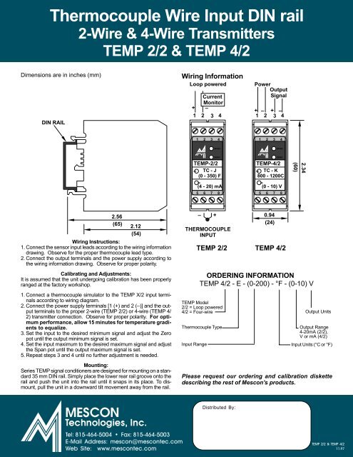
Thermocouple Wire Input DIN rail<br />
2-Wire & 4-Wire <strong>Transmitters</strong><br />
TEMP 2/2 & TEMP 4/2<br />
Dimensions are in inches (mm)<br />
DIN RAIL<br />
Wiring Information<br />
Loop powered<br />
Current<br />
Monitor<br />
+ –<br />
1 2 3 4<br />
Power<br />
Output<br />
Signal<br />
+ – + –<br />
1 2 3 4<br />
1 2 3 4<br />
1 2 3 4<br />
SPAN<br />
SPAN<br />
ZERO<br />
TEMP-2/2<br />
TC - J<br />
(0 - 350) F<br />
(4 - <strong>20</strong>) mA<br />
5 6 7 8<br />
ZERO<br />
TEMP-4/2<br />
TC - K<br />
800 - 1<strong>20</strong>0C<br />
(0 - 10) V<br />
5 6 7 8<br />
(60)<br />
2.34<br />
2.56<br />
(65)<br />
2.12<br />
(54)<br />
Wiring Instructions:<br />
1. Connect the sensor input leads according to the wiring information<br />
drawing. Observe for the proper thermocouple lead type.<br />
2. Connect the output terminals and the power supply according to<br />
the wiring information drawing. Observe for proper polarity.<br />
Calibrating and Adjustments:<br />
It is assumed that the unit undergoing calibration has been properly<br />
ranged at the factory workshop.<br />
1. Connect a thermocouple simulator to the TEMP X/2 input terminals<br />
according to wiring diagram.<br />
2. Connect the power supply terminals [1 (+) and 2 (–)] and the output<br />
terminals to the proper 2-wire (TEMP 2/2) or 4-wire (TEMP 4/<br />
2) transmitter connection. Observe for proper polarity. For optimum<br />
performance, allow 15 minutes for temperature gradients<br />
to equalize.<br />
3. Set the input to the desired minimum signal and adjust the Zero<br />
pot until the output minimum signal is set.<br />
4. Set the input maximum to the desired maximum signal and adjust<br />
the Span pot until the output maximum signal is set.<br />
5. Repeat steps 3 and 4 until no further adjustment is needed.<br />
Mounting:<br />
Series TEMP signal conditioners are designed for mounting on a standard<br />
35 mm DIN rail. Simply place the lower rear rail groove onto the<br />
rail and push the unit into the rail until it snaps in its place. To dismount,<br />
pull the unit in a downward tilt movement away from the rail.<br />
– +<br />
THERMOCOUPLE<br />
INPUT<br />
TEMP <strong>Model</strong><br />
2/2 = Loop powered<br />
4/2 = Four-wire<br />
0.94<br />
(24)<br />
TEMP 2/2 TEMP 4/2<br />
ORDERING INFORMATION<br />
TEMP 4/2 - E - (0-<strong>20</strong>0) - °F - (0-10) V<br />
Thermocouple Type<br />
Input Range<br />
Output Units<br />
Output Range<br />
4-<strong>20</strong>mA (2/2),<br />
V or mA (4/2)<br />
Input Units (°C or °F)<br />
Please request our ordering and calibration diskette<br />
describing the rest of Mescon's products.<br />
Distributed By:<br />
Tel: 815-464-5004 • Fax: 815-464-5003<br />
E-Mail Address: mescon@mescontec.com<br />
Web Site: www.mescontec.com<br />
TEMP 2/2 & TEMP 4/2<br />
11.97