The Developing of Myrinet Driver for DP System - Nectec
The Developing of Myrinet Driver for DP System - Nectec
The Developing of Myrinet Driver for DP System - Nectec

Create successful ePaper yourself
Turn your PDF publications into a flip-book with our unique Google optimized e-Paper software.
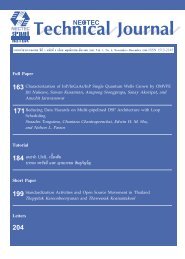
NECTEC Technical Journal, Vol. II, No. 9 200<br />
<strong>The</strong> Development <strong>of</strong> <strong>Myrinet</strong> <strong>Driver</strong> <strong>for</strong> <strong>DP</strong> Low Latency Message Passing<br />
<strong>System</strong><br />
<strong>The</strong>ewara Vorakosit, Putchong Uthayopas<br />
Parallel Research Group, CONSYL<br />
Department <strong>of</strong> Computer Engineering,<br />
Faculty <strong>of</strong> Engineering, Kasetsart University<br />
Bangkok, Thailand.<br />
Email: g4465018@ku.ac.th, pu@ku.ac.th<br />
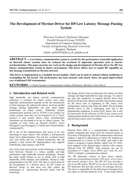
ABSTRACT -- Low-latency communication system is crucial <strong>for</strong> the per<strong>for</strong>mance <strong>of</strong> parallel application<br />
on Beowulf cluster systems since its reduced the overhead <strong>of</strong> important operation such as barrier<br />
synchronization. This paper presents our work on the design and development <strong>of</strong> <strong>Myrinet</strong> driver <strong>for</strong> <strong>DP</strong>, low<br />
latency communication system in cluster environment. This driver allows user to exploit <strong>DP</strong> capability on<br />
fast message transmission on <strong>Myrinet</strong> network.<br />
This driver is implemented as a loadable kernel module, which can be load or unload without modifying or<br />
recompiling the OS kernel. <strong>The</strong> per<strong>for</strong>mance has been measure and clearly shows the good improvement<br />
over traditional U<strong>DP</strong> transmission.<br />
KEYWORDS -- Cluster <strong>System</strong>, Communication Latency Reduction, <strong>Myrinet</strong>, Linux <strong>Driver</strong><br />
1. Introduction and Related work <strong>The</strong> design <strong>of</strong> driver aims at achieving a low latency <strong>for</strong> short<br />
High bandwidth, low latency network communication<br />
subsystem is essential <strong>for</strong> cluster system since many<br />
important synchronization depends on the fast transmission<br />
<strong>of</strong> short massages. By reducing the latency involved, parallel<br />
message passing applications can gain much higher<br />
per<strong>for</strong>mance on cluster system. Traditional Generic<br />
communication protocol such as TCP/IP is too complex <strong>for</strong><br />
cluster systems since they are not designed to be a “local”<br />
protocol in such system. Hence, many communication<br />
subsystems are developed to be use in cluster systems. <strong>The</strong><br />
examples <strong>of</strong> such works are Directed Point[7], Active<br />
Message[2], Fast Message[3], U-Net[4] and Virtual Interface<br />
Architecture[5].<br />
<strong>DP</strong> is one <strong>of</strong> the implementation that seems to be very<br />
interesting in many aspects. This includes a well-protected<br />
kernel level implementation, fast and low overhead system<br />
call, well define and low overhead architecture. But the<br />
problem is that current <strong>DP</strong> implementation only supports<br />
FastEthernet, share memory, and ATM.<br />
One <strong>of</strong> the most used network switch technology is <strong>Myrinet</strong><br />
from Myricom. <strong>Myrinet</strong> is a robust, scalable, and high<br />
per<strong>for</strong>mance high bandwidth network technology. <strong>Myrinet</strong><br />
has many useful features to use in cluster such as high<br />
bandwidth, ANSI standard, and scalability. <strong>Myrinet</strong> is fully<br />
programmable at the NIC level. This facts is a motivation <strong>for</strong><br />
the development <strong>of</strong> a <strong>Myrinet</strong> driver <strong>for</strong> <strong>DP</strong> system on<br />
Beowulf cluster so that users can fully exploit the<br />
per<strong>for</strong>mance <strong>of</strong> <strong>Myrinet</strong>-base Beowulf cluster with <strong>DP</strong><br />
technology.<br />
message and high bandwidth <strong>for</strong> large message. To achieve<br />
our goal, the complexity <strong>of</strong> original <strong>Myrinet</strong> driver from<br />
Myricom [6] has been reduced and other functionality require<br />
<strong>for</strong> the driver such as registering to <strong>DP</strong>, source route<br />
configuration, memory map utility are added. <strong>The</strong> developing<br />
<strong>Myrinet</strong> driver is still a challenging work due to the<br />
programming complexity in kernel level. Hence, this is also<br />
the motivation <strong>for</strong> the selection <strong>of</strong> GNU/Linux system as an<br />
implementation plat<strong>for</strong>m since GNU/Linux is a free s<strong>of</strong>tware<br />
and all kernel source code is available.<br />
2. Background<br />
Directed Point (<strong>DP</strong>) is a communication subsystem <strong>for</strong><br />
parallel computing that comes from the research project at<br />
University <strong>of</strong> Hong Kong. <strong>The</strong> <strong>DP</strong> communication subsystem<br />
employs a high-level abstraction to express the interprocess<br />
communication in a cluster. In <strong>DP</strong> model, each node in the<br />
cluster is assigned a logical identity called Node ID (NID).<br />
Each endpoint <strong>of</strong> the directed edge is labeled with a unique<br />
Directed Pont ID (<strong>DP</strong>ID). Each program can use an<br />
association <strong>of</strong> 3 tuples {local <strong>DP</strong>ID, peer Node ID, peer<br />
<strong>DP</strong>ID} to identify a communication channel.<br />
<strong>The</strong> <strong>DP</strong> subsystem consists <strong>of</strong> three layers, namely,<br />
application programming interface (API) layer, service layer,<br />
and network interface layer. <strong>The</strong> <strong>DP</strong> API layer provides a<br />
way to use <strong>DP</strong> system. <strong>The</strong> <strong>DP</strong> service layer is the core <strong>of</strong> the<br />
<strong>DP</strong> subsystem that provides services <strong>for</strong> message delivery.<br />
This layer is responsible <strong>for</strong> the delivering <strong>of</strong> messages from<br />
user space to network hardware level. It also helps deliver
NECTEC Technical Journal, Vol. II, No. 9 201<br />
the incoming packets to the target <strong>DP</strong> end point. <strong>The</strong> <strong>DP</strong><br />
network interface layer provides an interface <strong>for</strong> <strong>DP</strong> service<br />
layer to interact with the network hardware. Figure 1<br />
illustrates the <strong>DP</strong> system architecture.<br />
TBP<br />
API<br />
Outgoing<br />
Messages<br />
API Layer<br />
Incoming<br />
DM<br />
TBP<br />
Buffer<br />
Buffer<br />
Buffer<br />
RX FIFO<br />
Queue<br />
CAT<br />
RX Descriptor<br />
List<br />
RX Control Logic<br />
IOOR<br />
MDR<br />
Interrupt<br />
Handler<br />
Network Interface<br />
NART<br />
TX Descriptor<br />
List<br />
Buffer<br />
Buffer<br />
Buffer<br />
TX Control Logic TX FIFO<br />
Queue<br />
Service<br />
Layer<br />
Network<br />
Interface<br />
Layer<br />
Outgoing<br />
DM<br />
Hardware<br />
Figure 1. <strong>The</strong> architecture <strong>of</strong> <strong>DP</strong> communication subsystem<br />
<strong>Myrinet</strong> is a switching technology that is widely used to<br />
interconnection <strong>for</strong> high-per<strong>for</strong>mance cluster systems. Some<br />
features <strong>of</strong> <strong>Myrinet</strong> are:<br />
• Full-duplex 2+2 Gigabit/second links, switch ports,<br />
and interface ports.<br />
• Flow control, error control, and "heartbeat"<br />
continuity monitoring on every link.<br />
Figure 2. <strong>The</strong> block diagram <strong>of</strong> <strong>Myrinet</strong> NIC<br />
3. Implementation <strong>of</strong> <strong>Myrinet</strong> <strong>Driver</strong> <strong>for</strong><br />
<strong>DP</strong><br />
<strong>Myrinet</strong> driver is designed to work s a network layer <strong>of</strong> <strong>DP</strong>.<br />
<strong>The</strong> driver consists <strong>of</strong> 2 parts: the LANai control program<br />
and Linux Host <strong>Driver</strong>. LANai control program is a program<br />
that execute on LANai processor on <strong>Myrinet</strong> board. <strong>The</strong><br />
Linux host driver is a driver execute in Linux Kernel. <strong>The</strong><br />
Linux host driver and LANai control program communicate<br />
using hardware level share memory.<br />
In LANai, the memory available is a 2 MB SRAM<br />
(expandable to 8 MB). <strong>The</strong> LANai memory is divided into 7<br />
sections as follows:<br />
1. <strong>Myrinet</strong> control program region <strong>for</strong> <strong>Myrinet</strong> control<br />
program (MCP). <strong>The</strong> size <strong>of</strong> this program in our driver is<br />
about 256 kB. At the end <strong>of</strong> this region, it is a base stack<br />
pointer. We have to move base stack pointer to this<br />
address in order to use the rest <strong>of</strong> LANai memory. This<br />
region if from 0 to 0x3ffff.<br />
• Low-latency, cut-through, crossbar switches, with<br />
monitoring <strong>for</strong> high-availability applications. 2. Blank region that acts as a guard between MCP and other<br />
• Scalable to tens <strong>of</strong> thousands <strong>of</strong> hosts, with networkbisection<br />
data rates in Terabits per second, and can<br />
also provide alternative communication paths<br />
between hosts.<br />
• Host interfaces has build-in microcontroller called<br />
LANai that execute a control program to interact<br />
directly with host processes ("OS bypass") <strong>for</strong> lowlatency<br />
communication, and directly with the<br />
network to send, receive, and buffer packets.<br />
• Support any topology and protocol.<br />
• Con<strong>for</strong>m to American National Standard<br />
ANSI/VITA 26-1998<br />
<strong>Myrinet</strong> card has a memory space <strong>of</strong> 16 MB. LANai memory<br />
is between address 0 to 0x800000. <strong>The</strong> block diagram <strong>of</strong><br />
<strong>Myrinet</strong> card is shown in Figure 2.<br />
regions. This region is ranging from address 0x40000 to<br />
0x4ffff.<br />
3. Command region. This region allows host and LANai to<br />
write and read the commands and status codes such as<br />
sending command, busy flags and so more. This region<br />
ranges from address 0x50000 to 0x5ffff.<br />
4. DMA control block region. <strong>Myrinet</strong> NIC contains a<br />
DMA controller. <strong>The</strong> controller uses chains <strong>of</strong> control<br />
blocks stored in LANai memory to initiate DMAmastering<br />
operations. <strong>The</strong>re are 2 chains, one <strong>for</strong> sending<br />
and another one <strong>for</strong> receiving. This region is located at<br />
the address 0x60000 to 0x6ffff.<br />
5. Source route table region. This region is used to maintain<br />
the source route table. <strong>System</strong> administrator has to<br />
configure source route table <strong>for</strong> each node statically.<br />
When sending a packet, LANai will search <strong>for</strong> a source<br />
route <strong>for</strong> target host from <strong>DP</strong> header. This region is from<br />
0x70000 to 0x7ffff. In this version, the driver supports 6<br />
bytes source route. That means cluster can span to<br />
maximum <strong>of</strong> 6 switches or a few hundred nodes. This<br />
table can contain up to 21845 hosts.<br />
6. Send buffer. This region is used to store the outgoing<br />
packet to be sent. Only one packet can be stored in this<br />
region at a time. MCP supports up to 65536 bytes <strong>of</strong>
NECTEC Technical Journal, Vol. II, No. 9 202<br />
data. However, the current version <strong>of</strong> <strong>DP</strong> supports only<br />
1500 bytes. This region is ranging from address 0x9000<br />
to 0x9ffff.<br />
7. Receive buffer. This region is used to store the incoming<br />
packet. This region ranges from address 0x10000 to<br />
3. <strong>Driver</strong> triggers DMA transfer <strong>of</strong> incoming packet<br />
into host memory.<br />
4. <strong>Driver</strong> calls <strong>DP</strong> service layer to dispatch incoming<br />
packet.<br />
0x10ffff. • Memory-mapped function provides the mapping <strong>of</strong> all<br />
16MB <strong>of</strong> LANai memory space into a part <strong>of</strong> the user<br />
space. To use this function, user have to create a<br />
character device file with predefine major number and<br />
minor number to be 0. <strong>The</strong> function is used to debug<br />
<strong>Myrinet</strong>.<br />
For the driver to work, the LANai controller code has been<br />
developed using C language. This C code is the compiled to<br />
LANai machine code using cross compiler available from<br />
Myricom. <strong>The</strong> LANai is programmed logic is a state<br />
machine. Figure 3 shows the flowchart that explains the<br />
LANai controller code logic.<br />
Initilization<br />
Starting<br />
receive<br />
engine<br />
Incomming<br />
packet<br />
No<br />
Outgoing<br />
packet<br />
No<br />
Yes<br />
Yes<br />
Forward<br />
message<br />
to MDR<br />
engine<br />
Restarting<br />
receive<br />
engine<br />
Send it<br />
Figure 3. Flow chart <strong>for</strong> LANai Send Receive Operation<br />
For the Linux host driver, the driver consists <strong>of</strong> 4 main<br />
functions: sending function, receiving function, memorymapped<br />
function, and source route configuration and<br />
registration function. <strong>The</strong> operations <strong>of</strong> each function can be<br />
briefly summarized as follows:<br />
• Sending function responsible <strong>for</strong> the sending <strong>of</strong> outgoing<br />
packet. This module is called directly by <strong>DP</strong> service<br />
layer. <strong>The</strong> transmission <strong>of</strong> a message works as follow:<br />
1. <strong>Driver</strong> checks whether LANai is free.<br />
2. <strong>Driver</strong> creates <strong>DP</strong> header in kernel memory.<br />
• Source route configuration function provides a way to set<br />
source route <strong>for</strong> each node. Source route is required <strong>for</strong><br />
the sending <strong>of</strong> packets to other node. In order to keep the<br />
overhead low, the source route table are configure<br />
statically. Source route configuration is registered in a<br />
file /proc/net/myri_route. User can configure source<br />
route using cat command to /proc/net/myri_route. This<br />
file can also be read.<br />
<strong>The</strong> driver itself is implemented as a loadable kernel module.<br />
Hence, the driver can be loaded or unloaded from memory<br />
without modifying or recompiling the kernel. In order to<br />
support the listed functionally, driver composes <strong>of</strong> 7 major<br />
modules, which are:<br />
• Initialization module – this module responsible <strong>for</strong><br />
locating <strong>Myrinet</strong> NIC from a system using PCI function<br />
called in Linux and gets the pointer to configuration<br />
space if a <strong>Myrinet</strong> NIC is located. Next, the memory in<br />
<strong>Myrinet</strong> NIC is mapped as a part <strong>of</strong> kernel memory, so<br />
kernel can directly access the card. Finally, the routine<br />
will initialize <strong>Myrinet</strong> hardware, clear, and check all<br />
content <strong>of</strong> LANai memory.<br />
• Loading module – this module load MCP program to<br />
LANai memory. MCP code is programmed in C<br />
language, which is compiled by LANai cross compiler to<br />
LANai machine code. This machine code is then<br />
converted into C array definition in order to simplify the<br />
loading task. LANai executable file can be converted to<br />
C array using “gendat” utility from Myricom and then<br />
included into a driver source code. Loading task is<br />
simplified to be only the copy <strong>of</strong> array content to LANai<br />
memory.<br />
• Sending module. This module is a major part <strong>of</strong> this<br />
driver. Sending module is called by <strong>DP</strong> service region to<br />
send a packet to another node.<br />
3. Copy the header and data to LANai memory. • Interrupt service routine. This routine is another major<br />
4. Wait until the send operation in LANai completed. part <strong>of</strong> the driver. This routine is called when LANai<br />
interrupts host. LANai will interrupt host only when an<br />
• Receiving function receives the incoming packet. LANai<br />
will receive all incoming packet at all time. If there is an<br />
incoming packet, the routine works the following way:<br />
incoming packet is a <strong>DP</strong> packet. This routine also help<br />
copy the data from LANai memory to <strong>DP</strong> service layer<br />
buffer.<br />
1. LANai checks that there is an incoming packet and<br />
whether the incoming packet is a <strong>DP</strong> packet or not.<br />
2. LANai set the size <strong>of</strong> incoming packet in DMA<br />
control block and raises the interrupt to host driver.<br />
• Character device and /proc Routine. This routine<br />
provides a convenient way to directly access the NIC.<br />
User can directly access a whole NIC as though the NIC<br />
is in user space using mmap system call as well as<br />
generic read/write system call. /proc provide a
NECTEC Technical Journal, Vol. II, No. 9 203<br />
convenient way to configure source route <strong>for</strong> that node.<br />
This module will create /proc/net/myri_route.<br />
• Post-initialization module. <strong>The</strong> main function <strong>of</strong> this<br />
module is to register components such as interrupt<br />
service routine to a kernel. After finish the registration<br />
process, this routine will start the LANai operation.<br />
• Clean up module. <strong>The</strong> driver can be unloaded from<br />
kernel using the rmmod command. <strong>The</strong> rmmod command<br />
will call clean up module to free all resources that are<br />
allocated during the work. Hence, this module has to free<br />
all resources be<strong>for</strong>e the driver are unloaded from kernel.<br />
<strong>The</strong> resource cleaned are things such as memory,<br />
interrupt line, /proc and so on.<br />
4. Per<strong>for</strong>mance<br />
<strong>The</strong> driver has been tested using 2 nodes from a Beowulf<br />
cluster called AMATA. <strong>The</strong>se two system has the following<br />
setup: 1 GHz Athlon processor with 512 MB RAM connect<br />
through <strong>Myrinet</strong> switch, Linux Kernel 2.2.16, and <strong>Myrinet</strong><br />
card model: M2M-PCI64A-2-50973 with LANai version <strong>of</strong><br />
7.2 and 2 MB board memory.<br />
A ping-pong program has been developed to measure the<br />
round-trip time <strong>for</strong> message size ranging from 8 bytes to<br />
1024 bytes. <strong>The</strong> comparison has been made between the<br />
newly developed driver and the per<strong>for</strong>mance <strong>of</strong> code with<br />
U<strong>DP</strong> over FastEthernet, U<strong>DP</strong> over <strong>Myrinet</strong>, and GM driver<br />
over myrinet. <strong>The</strong> results are as shown in Table 1 and the<br />
graph are plotted as illustrated in Figure 4. <strong>The</strong> time given in<br />
Table 1 is in the unit <strong>of</strong> Microsecond.<br />
Table 1. Comparison <strong>of</strong> U<strong>DP</strong> over Fast Ethernet, <strong>Myrinet</strong><br />
and <strong>DP</strong> over <strong>Myrinet</strong><br />
Message<br />
size<br />
U<strong>DP</strong><br />
Fast<br />
Ethernet<br />
U<strong>DP</strong><br />
<strong>Myrinet</strong><br />
<strong>DP</strong><br />
<strong>Myrinet</strong><br />
GM<br />
<strong>Myrinet</strong><br />
1 52.3 62.8 26.25 15.99<br />
2 47.8 47.8 26.75 15.98<br />
4 48.5 47.8 27 16.02<br />
8 48.0 47.0 27 16.02<br />
16 46.8 47.0 27 16.02<br />
32 48.5 48.0 27.25 15.96<br />
64 51.8 49.0 28.25 16.78<br />
128 53.5 52.5 29.75 19.98<br />
256 58.0 61.8 36.5 30.18<br />
512 68.5 68.3 40.25 38.42<br />
1024 88.3 88.5 51.5 55.16<br />
For the new driver, the graph in Figure 4 clearly shows a<br />
much lower latency compared to usual U<strong>DP</strong> over both<br />
<strong>Myrinet</strong> and Fast Ethernet. When compared with GM driver<br />
from Myricom, <strong>for</strong> small message size, GM driver is a little<br />
bit faster (about 10 Microsecond) that our <strong>DP</strong> driver. <strong>The</strong> <strong>DP</strong><br />
driver has slightly lower latency when message size is larger<br />
than 512 bytes. <strong>The</strong> time different may cause by many<br />
factors. One <strong>of</strong> the most important factor is how fine tune the<br />
code has been done. <strong>The</strong> logical step to further fine tune the<br />
code is to pr<strong>of</strong>ile them in more detail and look at the code<br />
tuning at assembly language level.<br />
Latency time (usec)<br />
100<br />
90<br />
80<br />
70<br />
60<br />
50<br />
40<br />
30<br />
20<br />
10<br />
0<br />
Latency Comparison<br />
U<strong>DP</strong>/FastEthernet<br />
U<strong>DP</strong>/<strong>Myrinet</strong><br />
<strong>DP</strong>/<strong>Myrinet</strong><br />
GM/<strong>Myrinet</strong><br />
0 200 400 600 800 1000 1200<br />
Message size (bytes)<br />
Figure 4. Per<strong>for</strong>mance comparison between <strong>Myrinet</strong> over <strong>DP</strong> and U<strong>DP</strong>
NECTEC Technical Journal, Vol. II, No. 9 204<br />
5. Conclusion and Future Work<br />
In this paper, an implementation <strong>of</strong> <strong>Myrinet</strong> driver <strong>for</strong> <strong>DP</strong><br />
system has been discussed with the experimental results. <strong>The</strong><br />
techniques used in developing the driver have been<br />
explained. From the experimental results, the newly<br />
developed driver shown a satisfactory reduction <strong>of</strong> message<br />
latency although, there seems to be slight problem that slow<br />
down the <strong>Myrinet</strong> hardware transmission.<br />
In the future, this driver will be used as a communication<br />
subsystem under a planned Pico-MPI that will be developed<br />
later. This implementation aims to explore the full optimize<br />
<strong>of</strong> message passing implementation from user space level to<br />
kernel level which has a high potential to generate fast and<br />
compact experimental MPI implementation.<br />
6. Acknowledgement<br />
This research has been partly supported by KU research and<br />
Development Institute under SRU grant. Most <strong>of</strong> the<br />
equipment used in the developed is sponsored by AMD Far<br />
East Inc.<br />
7. References<br />
[1] Chun-Ming Lee, Anthony Tam, and Cho-Li Wang,<br />
Directed Point: An Efficient Communication Subsystem<br />
<strong>for</strong> Cluster Computing, <strong>The</strong> University <strong>of</strong> Hong Kong,<br />
1997<br />
[2] T. von Eichken, D. E. Culler, S. C. goldstein and K. E.<br />
Schauser, Active Message: a Mechanism <strong>for</strong> Integrated<br />
Communication and Computation,” <strong>The</strong> 19 th Int’l on<br />
Computer Architecture, 1992<br />
[3] S. Palin, M. Lauria and A. Chien, “High Per<strong>for</strong>mance<br />
Messages (FM) <strong>for</strong> <strong>Myrinet</strong>,” Supercomputing, 1995<br />
[4] Thorsten von Eicken, Anindya Basu, Vineet Buch, and<br />
Werner Vogels, U-Net: A user-level network interface<br />
<strong>for</strong> parallel and distributed computing. In Proceedings <strong>of</strong><br />
the 15th ACM Symposium on Operating <strong>System</strong>s<br />
Principles, December 1995. Available from<br />
http://www.cs.cornell.edu/Info/Projects/ATM/sosp.ps<br />
[5] D. Dunning and G. Regnier. <strong>The</strong> virtual interface<br />
architecture. InHot Interconnects V, pages 47--58, 1997<br />
[6] Myricom Inc, M2M PCI64A Product Specification,<br />
http://www.myri.com/myrinet/PCI64/m2m-pci64a.html,<br />
July 2000<br />
[7] Myricom Inc, PCI64 Programmer's Documentation,<br />
http://www.myri.com/myrinet/PCI64/<br />
programming.html, July 2000