
You also want an ePaper? Increase the reach of your titles
YUMPU automatically turns print PDFs into web optimized ePapers that Google loves.
MANUAL<br />
Simrad <strong>AP16</strong><br />
Autopilot
This page is intentionally left blank
Instruction manual<br />
Instruction <strong>Manual</strong><br />
This manual is intended as a reference guide for operating and<br />
correctly installing the <strong>AP16</strong> autopilot.<br />
Great care has been paid to simplify operation and set-up of the<br />
Simrad <strong>AP16</strong>, however, an autopilot is a complex electronic<br />
system. It is affected by sea conditions, speed of the vessel, hull<br />
shape and size.<br />
Please take time to read this manual to get a thorough<br />
understanding of the operation and system components and their<br />
relationship to a complete <strong>AP16</strong> autopilot system.<br />
Other documentation material that is included in this manual is a<br />
warranty card. This must be filled out by the authorized dealer that<br />
performed the installation and mailed in to activate the warranty.<br />
<strong>20221560B</strong> 1
Simrad <strong>AP16</strong> Autopilot<br />
Document revisions<br />
Rev Date Written by Checked by Approved by<br />
A 19.03.04 NG ThH ThH<br />
B 03.05.04<br />
Document history<br />
Rev. A<br />
Rev. B<br />
First edition.<br />
Part no. for AC40 Power PCB ass’y, page 119 corrected. Added notes in<br />
chapter 3.19. Minor corrections in text and display pictures.<br />
2 <strong>20221560B</strong>
Instruction manual<br />
Contents<br />
1 System description .......................................................................................9<br />
1.1 General ..................................................................................................9<br />
1.2 How to use this manual.........................................................................9<br />
1.3 System components.............................................................................10<br />
1.4 <strong>AP16</strong> Control Unit ..............................................................................11<br />
1.5 Autopilot Computer ............................................................................11<br />
1.6 RF300 Rudder Feedback unit .............................................................11<br />
1.7 Heading Sensors..................................................................................12<br />
RFC35 Electronic Fluxgate Compass.................................................12<br />
RC36 Rate compass (optional) ...........................................................12<br />
NMEA compass (optional) .................................................................12<br />
Simrad RGC10 and RGC50 gyrocompasses ......................................12<br />
1.8 Optional equipment.............................................................................13<br />
R3000X Remote Control ....................................................................13<br />
JS10 Joystick.......................................................................................13<br />
Multiple stations..................................................................................13<br />
2 Operation....................................................................................................15<br />
2.1 Overview.............................................................................................15<br />
2.2 ON/OFF - Standby mode....................................................................16<br />
Flashing course knob icon ..................................................................17<br />
Alarms.................................................................................................17<br />
2.3 <strong>AP16</strong> with MSD50 Stern Drive unit...................................................17<br />
Zero point setting ................................................................................18<br />
2.4 Non-Follow-Up steering (NFU) .........................................................18<br />
2.5 R3000X Remote Control (NFU).........................................................19<br />
2.6 JS10 Joystick (NFU) ...........................................................................20<br />
2.7 Automatic Steering .............................................................................20<br />
Heading catch......................................................................................21<br />
<strong>20221560B</strong> 3
Simrad <strong>AP16</strong> Autopilot<br />
2.8 Automatic control of steering parameters...........................................21<br />
Power boats.........................................................................................21<br />
Sailboat................................................................................................22<br />
2.9 <strong>Manual</strong> Parameter Selection ...............................................................22<br />
2.10 U-turn ..................................................................................................23<br />
2.11 Dodge in AUTO..................................................................................24<br />
2.12 Tacking in Auto mode ........................................................................25<br />
2.13 Navigating with the <strong>AP16</strong>...................................................................25<br />
Setting the waypoint arrival circle ......................................................27<br />
2.14 Dodge in NAV ....................................................................................28<br />
2.15 Selecting a different Navigation source..............................................29<br />
2.16 Wind vane steering..............................................................................29<br />
2.17 Tacking in Wind mode........................................................................31<br />
Gybing.................................................................................................32<br />
Tack and gybe prevent ........................................................................32<br />
2.18 Wind steering and navigation .............................................................33<br />
Operating in WIND NAV mode.............................................................35<br />
RACING .............................................................................................35<br />
2.19 Multiple station system .......................................................................36<br />
2.20 Lock function ......................................................................................36<br />
2.21 User Set-up Menu ...............................................................................37<br />
Alternating Course Knob Icon............................................................37<br />
STANDBY Mode ...............................................................................38<br />
AUTO Mode .......................................................................................43<br />
NAV Mode..........................................................................................44<br />
WIND Mode .......................................................................................44<br />
2.22 INFO menu .........................................................................................45<br />
Course knob icon ................................................................................47<br />
INFO menu flowchart .........................................................................47<br />
INFO menu and Main screen active unit ............................................48<br />
INFO menu and Main Screen, inactive unit .......................................48<br />
4 <strong>20221560B</strong>
Instruction manual<br />
3 Installation..................................................................................................49<br />
3.1 General ................................................................................................49<br />
3.2 Installation checklist ...........................................................................49<br />
3.3 Unpacking and handling .....................................................................50<br />
3.4 Determine system configuration .........................................................50<br />
3.5 <strong>AP16</strong> System Layout ..........................................................................51<br />
3.6 RF300 Rudder feedback installation...................................................51<br />
3.7 Autopilot computer installation ..........................................................53<br />
3.8 Cable connections ...............................................................................53<br />
3.9 Grounding and RFI .............................................................................54<br />
3.10 Drive unit installation..........................................................................56<br />
Connecting a reversible pump ............................................................58<br />
Connecting a hydraulic linear drive....................................................59<br />
Connecting a solenoid valve ...............................................................59<br />
3.11 Control unit installation ......................................................................60<br />
Panel mounting ...................................................................................60<br />
Optional bracket mounting .................................................................60<br />
3.12 ROBNET2 network cables .................................................................61<br />
AP27 connection.................................................................................63<br />
3.13 RFC35 Fluxgate Compass installation ...............................................63<br />
3.14 RC36 Rate Compass installation ........................................................65<br />
3.15 R3000X Remote Control installation .................................................65<br />
3.16 JS10 Joystick.......................................................................................66<br />
3.17 S35 NFU Lever installation ................................................................66<br />
3.18 Interfacing ...........................................................................................66<br />
3.19 SimNet.................................................................................................67<br />
SimNet network cables .......................................................................67<br />
SimNet power and termination ...........................................................67<br />
3.20 Single NMEA input/output.................................................................72<br />
3.21 Double NMEA input/output ...............................................................72<br />
3.22 NMEA output on Port 2......................................................................73<br />
<strong>20221560B</strong> 5
Simrad <strong>AP16</strong> Autopilot<br />
3.23 NMEA Compass input........................................................................73<br />
3.24 Radar Clock/Data................................................................................74<br />
3.25 IS15 Instrument installation................................................................74<br />
3.26 External Alarm....................................................................................75<br />
3.27 LF3000 Linear Feedback ....................................................................76<br />
4 Configuration and setup ...........................................................................79<br />
4.1 First time turn on.................................................................................79<br />
4.2 Description of Installation Settings.....................................................80<br />
4.3 Installation Menu ................................................................................81<br />
Language selection..............................................................................83<br />
4.4 Dockside settings ................................................................................83<br />
Boat type .............................................................................................84<br />
Drive unit voltage................................................................................84<br />
Rudder Feedback Calibration .............................................................85<br />
Rudder Test.........................................................................................86<br />
Drive engage .......................................................................................87<br />
Rudder Deadband................................................................................88<br />
Wind setup ..........................................................................................88<br />
Minimum wind angle (NORMAL).....................................................89<br />
Minimum wind angle (RACING).......................................................89<br />
Tack angle (RACING)........................................................................89<br />
Tack time (RACING)..........................................................................90<br />
Wind shift alarm limit (RACING)......................................................90<br />
4.5 Interface Settings.................................................................................91<br />
4.6 Display units .......................................................................................91<br />
4.7 Sea Trial ..............................................................................................92<br />
Set Rudder zero...................................................................................93<br />
Minimum rudder .................................................................................93<br />
Compass calibration............................................................................94<br />
Compass Offset ...................................................................................96<br />
Wind Offset.........................................................................................97<br />
6 <strong>20221560B</strong>
Instruction manual<br />
Wind damping.....................................................................................97<br />
Depth Offset........................................................................................98<br />
Automatic tuning.................................................................................98<br />
Transition Speed .................................................................................99<br />
Init NAV ...........................................................................................100<br />
4.8 Parameters.........................................................................................101<br />
<strong>Manual</strong> parameter adjust...................................................................101<br />
Recall Autotuned?.............................................................................103<br />
4.9 Service Menu ....................................................................................104<br />
System Data Menu............................................................................104<br />
SimNet and NMEA Data Screen ......................................................105<br />
NMEA Port test (AC hardware) .......................................................107<br />
SimNet setup .....................................................................................107<br />
Master Reset......................................................................................109<br />
Final sea trial.....................................................................................109<br />
Providing user training......................................................................110<br />
5 Maintenance .............................................................................................111<br />
5.1 Control unit .......................................................................................111<br />
5.2 Autopilot Computer ..........................................................................111<br />
5.3 Rudder Feedback...............................................................................111<br />
5.4 Compass ............................................................................................111<br />
5.5 Drive unit ..........................................................................................111<br />
5.6 Exchange of software programme ....................................................112<br />
Autopilot Computer ..........................................................................112<br />
Autopilot Control Unit......................................................................113<br />
6 Trouble shooting ......................................................................................114<br />
6.1 Alarms...............................................................................................114<br />
7 Spare Parts List........................................................................................119<br />
8 Technical Specifications ..........................................................................122<br />
8.1 <strong>AP16</strong> Autopilot System ....................................................................122<br />
<strong>20221560B</strong> 7
Simrad <strong>AP16</strong> Autopilot<br />
8.2 <strong>AP16</strong> Control Unit ............................................................................123<br />
8.3 Autopilot Computers.........................................................................125<br />
8.4 RFC35 Fluxgate compass .................................................................127<br />
8.5 RC36 Rate compass ..........................................................................128<br />
8.6 RF300 Rudder Feedback...................................................................128<br />
8.7 R3000X Remote Control ..................................................................130<br />
8.8 JS10 Joystick.....................................................................................130<br />
8.9 IS15 Rudder ......................................................................................131<br />
8.10 SimNet...............................................................................................132<br />
8.11 IP protection......................................................................................133<br />
8.12 NMEA and SimNet messages...........................................................134<br />
9 Glossary ....................................................................................................138<br />
10 Index..........................................................................................................141<br />
SALES AND SERVICE WORLDWIDE<br />
TERMS OF WARRANTY<br />
WARRANTY CARD<br />
8 <strong>20221560B</strong>
System Description<br />
1 SYSTEM DESCRIPTION<br />
1.1 General<br />
Congratulations on the purchase of your new Simrad <strong>AP16</strong><br />
autopilot system and thank you for selecting what we feel is the<br />
most advanced autopilot system available on the market today.<br />
Today, Simrad manufactures a complete range of autopilots for<br />
all types of vessels, from recreational boats to merchant marine<br />
vessels. Our factory for these products, Simrad Egersund AS, is<br />
located in Egersund on the southwest coast of Norway. The<br />
company's involvement in autopilots began in 1953 with<br />
equipment for the North Sea fishing fleet under the brand name<br />
Robertson. Professional mariners around the world acknowledge<br />
that the Robertson and Simrad brand names are synonymous<br />
with the absolute best in autopilot technology.<br />
The Simrad <strong>AP16</strong> autopilot represents yet another step forward<br />
in autopilot technology with the intent of providing leisure boats<br />
between 30 and 80 foot with a host of new features. The system<br />
can be expanded and enhanced with a selection of options and<br />
accessories.<br />
The brain in the <strong>AP16</strong> autopilot system is the single "intelligent"<br />
autopilot computer that communicates on the Robnet2 network.<br />
The Robnet2 has been developed to establish a reliable digital<br />
communication and power distribution network between the<br />
units in the autopilot system.<br />
With the <strong>AP16</strong> autopilot Simrad introduces the SimNet data and<br />
control network. SimNet provides high speed data transfer and<br />
control of Simrad products integrated in a total steering and<br />
navigation system.<br />
1.2 How to use this manual<br />
This manual is intended as a reference guide for operating,<br />
installing and maintaining the Simrad <strong>AP16</strong> autopilot. Great care<br />
has been paid to simplify operation and set-up of the <strong>AP16</strong>.<br />
Please take time to read this manual to get a thorough<br />
understanding of the operation and system components and their<br />
relationship to a complete <strong>AP16</strong> autopilot system.<br />
<strong>20221560B</strong> 9
Simrad <strong>AP16</strong> Autopilot<br />
Other documentation material that is provided with your system<br />
includes a warranty card. This must be filled out by the<br />
authorized dealer that performed the installation and mailed in to<br />
activate the warranty.<br />
1.3 System components<br />
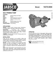
A basic <strong>AP16</strong> system consists of the following units (refer to<br />
Figure 1-1):<br />
− <strong>AP16</strong> Control Unit with accessories<br />
− Autopilot Computer<br />
− Fluxgate compass<br />
− Rudder Feedback Unit with transmission link<br />
− Drive unit<br />
The basic system can be expanded with fixed and hand held<br />
multiple full function control units, hand held remote and<br />
steering lever.<br />
Figure 1-1 <strong>AP16</strong> Basic system<br />
10 <strong>20221560B</strong>
System Description<br />
1.4 <strong>AP16</strong> Control Unit<br />
A compact autopilot control for panel, bulkhead or bracket<br />
mounting. It has a multifunction LCD display for readout of<br />
autopilot data, mode keys and course adjust keys. It has two<br />
Robnet2 connectors for system interconnection and expansion<br />
and two SimNet connectors for control and data sharing with<br />
other Simrad products. A NMEA2000 Adapter Cable is available<br />
for interface through a SimNet port (page 121).<br />
1.5 Autopilot Computer<br />
The autopilot computer is the heart in the <strong>AP16</strong> autopilot system.<br />
It contains the steering computer, interface other system<br />
components, NMEA 0183 interface and drive electronics for the<br />
drive unit motor and clutch. Three models, AC10, AC20 and<br />
AC40 are available.<br />
Autopilot computer comparison chart:<br />
AC10 AC20 (AC40)<br />
Supply voltage 10-28 V 10-40 V<br />
Motor current (continuous/peak) 6/10 A 10/20A (20/40A)<br />
Clutch/bypass current 1,5 A* 1,5 A*<br />
Number of control units 2 7<br />
NMEA 0183 ports (input/output) 1 2<br />
Solenoid output x x<br />
Input for NFU control x x<br />
External alarm<br />
Radar clock/data interface<br />
Input for NMEA compass<br />
* 3A on later models<br />
1.6 RF300 Rudder Feedback unit<br />
Rudder feedback unit with transmission link and 10 m (30 feet)<br />
of cable. Transforms the angular travel of the rudder to a digital<br />
signal read by the autopilot steering computer.<br />
x<br />
x<br />
x<br />
<strong>20221560B</strong> 11
Simrad <strong>AP16</strong> Autopilot<br />
1.7 Heading Sensors<br />
The <strong>AP16</strong> autopilot can be used with the following combinations<br />
of heading sensors:<br />
RFC35 Electronic Fluxgate Compass<br />
A compact heading sensor from Simrad with 15 m (45 feet) of<br />
cable. The direction of the earth's magnetic field is sensed by a<br />
floating ring core in a fluxgate coil and transformed to a digital<br />
signal read by the autopilot steering computer.<br />
RFC35 comes as standard with the autopilot.<br />
RC36 Rate compass (optional)<br />
Fluxgate compass with integrated rate sensor. Provides a dramatic<br />
improvement to the dynamic performance of both the autopilot<br />
and a stabilized radar display.<br />
NMEA compass (optional)<br />
A well performing compass that outputs NMEA 0183 HDT or<br />
HDG messages at 10 Hz can be connected directly to the AC20<br />
or AC40 autopilot computer.<br />
It is absolutely necessary for the autopilot that the heading rate is<br />
minimum 10 Hz.<br />
Simrad RGC10 and RGC50 gyrocompasses<br />
The optional GI51 unit is needed to interface the two<br />
gyrocompass models. Ask your Simrad dealer for information.<br />
12 <strong>20221560B</strong>
System Description<br />
1.8 Optional equipment<br />
A series of options are available for the basic <strong>AP16</strong> system.<br />
R3000X Remote Control<br />
A small handheld remote control with two push buttons for<br />
power steering or course selection (port and starboard), and one<br />
push button with built-in lighted indicator for limited mode<br />
change.<br />
JS10 Joystick<br />
The JS10 Joystick is a Non-Follow-Up steering lever designed<br />
for indoor and outdoor console mount. It has a spring-loaded<br />
return-to-mid-position feature and is equipped with 10 m (33’) of<br />
cable and installation hardware.<br />
Multiple stations<br />
Multiple control units can be added to the system. See<br />
comparison chart on page 11.<br />
<strong>20221560B</strong> 13
Simrad <strong>AP16</strong> Autopilot<br />
This page is intentionally left blank.<br />
14 <strong>20221560B</strong>
Operation<br />
2 OPERATION<br />
WARNING !<br />
An autopilot is a very useful navigational aid, but DOES<br />
NOT under any circumstance replace a human navigator.<br />
Do not use automatic steering when:<br />
• In heavy traffic areas or in narrow waters<br />
• In poor visibility or extreme sea conditions<br />
• When in areas where use of autopilot is<br />
prohibited by law<br />
When using an autopilot:<br />
• Do not leave the helm unattended<br />
• Do not place any magnetic material or<br />
equipment near heading sensor used in the<br />
autopilot system<br />
• Verify at regular intervals course and position of<br />
vessel<br />
• Always switch to Standby mode and reduce<br />
speed in due time to avoid hazardous situations<br />
2.1 Overview<br />
Multifunction LCD<br />
STANDBY mode / POWER on/off<br />
INSTRUMENT screens/ setup menus<br />
AUTO mode<br />
NAV or WIND mode<br />
STBY<br />
PWR<br />
INFO<br />
SETUP<br />
AUTO<br />
NAV<br />
WIND<br />
1<br />
10<br />
10<br />
TURN<br />
DODGE<br />
PORT keys 1/10°<br />
TURN/ DODGE<br />
STARBOARD keys 1/10°<br />
1<br />
<strong>20221560B</strong> 15
Simrad <strong>AP16</strong> Autopilot<br />
The control unit shown above can operate as a stand alone unit<br />
in an autopilot system or combined in a multistation system. In a<br />
multistation system the command can easily be transferred from<br />
one unit to another. <strong>AP16</strong> units not in control will display the<br />
icon.<br />
The <strong>AP16</strong> system is capable of the following primary steering<br />
modes: STBY (power steering), AUTO, NAV and WIND, each<br />
mode having a dedicated push button.<br />
Each of the mode push buttons is clearly identified with the<br />
primary function in large text, and a secondary function listed in<br />
smaller text. Each button provides you with a multiple function<br />
mode display.<br />
A group of user adjustable settings are provided in the <strong>AP16</strong><br />
User Setup Menu (page 37).<br />
Alarms are presented in plain text to alert you of system and<br />
external data failure conditions. Alarms include both audible and<br />
visual presentations. The alarm listing is on page 114.<br />
2.2 ON/OFF - Standby mode<br />
Note ! At first time turn on see paragraph 4.1.<br />
A single press on the STBY button switches the system ON and<br />
the following status displays are shown:<br />
Autopilot model<br />
Software version<br />
SimNet no.<br />
Autopilot computer model<br />
Software version<br />
Power board revision<br />
Main board revision<br />
Simrad<br />
<strong>AP16</strong><br />
SW 1.0.00<br />
HW rev. 00<br />
Sn xxxxxx<br />
Simrad<br />
AC20<br />
SW 1.0.00<br />
P00 M00 S000<br />
Software release<br />
Hardware revision<br />
Software release<br />
Self check<br />
SW and HW revisions shown are examples only.<br />
16 <strong>20221560B</strong>
Operation<br />
Note !<br />
After approximately 5 seconds, the system is operative and the<br />
unit that was turned on will show the Standby mode display.<br />
Other units in a multistation system will display "Inactive"<br />
and/or depending on model. Control is transferred to any<br />
single unit by pressing its’ STBY button.<br />
A long press (2-3 sec.) on the STBY button switches the system<br />
OFF and during this time, the alarm will sound.<br />
In an emergency, it is possible, on a multistation system, to turn<br />
OFF the system at any control unit by pressing the STBY button<br />
for 2-3 seconds.<br />
STBY mode is the mode that is used when steering the boat at<br />
the helm.<br />
Display information:<br />
− Standby mode<br />
− Current heading 345°M<br />
− Compass source: Rate<br />
compass<br />
− Rudder angle 00°.<br />
Flashing course knob icon<br />
When the PORT and STBD buttons are is used for settings<br />
etc., an icon will flash on the screen to tell that no course<br />
changes can be made unless you press the AUTO button.<br />
Alarms<br />
In the event there is an audible alarm with explaining text on the<br />
control unit, refer to section 6 Trouble shooting.<br />
2.3 <strong>AP16</strong> with MSD50 Stern Drive unit<br />
Note !<br />
The information in section 2.3 only applies if your autopilot is<br />
driving a Simrad MSD50 Stern Drive.<br />
The MSD50 Stern drive unit has a relative feedback signal which<br />
needs a zero point setting after the autopilot has been turned on.<br />
Refer to the MSD50 manual for further information.<br />
<strong>20221560B</strong> 17
Simrad <strong>AP16</strong> Autopilot<br />
Note !<br />
Zero point setting<br />
If you do not need a rudder angle display when leaving the dock,<br />
just steer the boat manually on a straight course and press the<br />
AUTO button. The zero point is then set automatically.<br />
If you prefer to use the rudder angle display when leaving the<br />
dock, proceed as follows:<br />
After turn on the rudder<br />
angle display will alternate<br />
between 10 degrees port and<br />
starboard to indicate that the<br />
"rudder" zero point need be<br />
set.<br />
Use the wheel to bring the "rudder" to midship position. Turn the<br />
wheel from lock to lock (H.O. to H.O.) and count the exact<br />
number of turns. Then start from one lock position and turn the<br />
half number of turns.<br />
AUTO STBY<br />
Press AUTO and then STBY. The zero point is now set and the<br />
display will show:<br />
Follow the operating<br />
instructions on the following<br />
pages. There is no further<br />
need for zero point settings<br />
until next time you turn the<br />
autopilot on.<br />
2.4 Non-Follow-Up steering (NFU)<br />
In Standby mode, the NFU display is presented when the PORT<br />
or STBD button is pressed. The rudder will move as long as the<br />
button is pressed and the rudder angle is shown on the display.<br />
18 <strong>20221560B</strong>
Operation<br />
1<br />
1<br />
Note !<br />
Activates<br />
PORT rudder<br />
command<br />
Activates<br />
STBD<br />
rudder<br />
command<br />
When a NFU steering lever or remote control is operated, other<br />
control units become “Inactive”.<br />
2.5 R3000X Remote Control (NFU)<br />
SIMRAD<br />
STBY-AUTO<br />
Simrad R3000X<br />
Push button for<br />
Port and Stbd<br />
commands<br />
STBY/automatic.<br />
Automatic modes<br />
are active when<br />
the lamp is lit.<br />
In STANDBY mode, the rudder will<br />
move as long as the Port or Stbd<br />
button is pressed.<br />
In AUTO mode and Wind modes the<br />
set course or set wind angle will<br />
change 1° each time the button is<br />
pressed.<br />
Note!<br />
If you keep the button pressed, it will<br />
automatically change the setting in<br />
increments of 3° per second.<br />
Mode changes are as per table below.<br />
Initial mode 1 st press 2 nd press<br />
STBY<br />
AUTO<br />
STBY<br />
Notes !<br />
1. When NAV mode is selected in<br />
User Setup<br />
2. When WIND mode is selected in<br />
User Setup<br />
3. NAV and WIND N modes can only<br />
be entered from the Control unit<br />
because you have to accept the<br />
prompt displays.<br />
AUTO<br />
NAV<br />
STBY<br />
AUTO<br />
WIND<br />
WINDN<br />
STBY<br />
STBY<br />
WIND<br />
STBY<br />
STBY<br />
STBY<br />
AUTO<br />
AUTO 1)3)<br />
STBY 2)<br />
WIND 2)<br />
WIND 2)<br />
WIND 3)<br />
<strong>20221560B</strong> 19
Simrad <strong>AP16</strong> Autopilot<br />
2.6 JS10 Joystick (NFU)<br />
Note !<br />
The principle is similar to that of R3000X Remote Control (see<br />
above). The rudder will move as long as the lever is offset to<br />
Port or Starboard. JS10 has no mode change feature.<br />
When a NFU steering lever or a remote control is operated, the<br />
control units become "Inactive".<br />
2.7 Automatic Steering<br />
When AUTO mode is selected, the <strong>AP16</strong> automatically picks the<br />
current boat heading as the set course and maintains the<br />
simultaneous rudder angle. This gives a bumpless transfer at the<br />
mode change.<br />
Automatic steering mode<br />
Set course: 340 degrees<br />
Compass reading: 340°M<br />
Steering parameter: LO-A<br />
Rudder angle: 00°<br />
The <strong>AP16</strong> will keep the boat on the set course until a new mode<br />
is selected or a new course is set with the PORT or STBD<br />
buttons.<br />
Port course<br />
adjust, 1°/push<br />
1 10 10 1<br />
Port course<br />
change,<br />
10°/push<br />
Stbd. course<br />
change<br />
10°/push<br />
Course<br />
adjust<br />
1°/push<br />
Once the course is changed to a new set course, the boat will<br />
automatically turn to the new heading and continue to steer<br />
straight.<br />
20 <strong>20221560B</strong>
Operation<br />
Heading catch<br />
When in AUTO modes this feature allows you to automatically<br />
cancel the turn you are in by an instant press on the AUTO<br />
button. The autopilot will counteract the turn and the boat will<br />
continue straight ahead on the heading read from the compass<br />
the very moment you pressed the AUTO button.<br />
Automatic steering mode<br />
New “caught” heading: 305°<br />
Compass reading: 301° M<br />
(magnetic) or T (true)<br />
Steering parameter: LO-A<br />
Rudder angle: 01° to stbd.<br />
STBY<br />
Regain manual steering by pressing the STBY button<br />
2.8 Automatic control of steering parameters<br />
The <strong>AP16</strong> provides two different sets of steering parameters for<br />
controlling the response of the boat at different speeds or wind<br />
directions while in AUTO, NAV or WIND modes.<br />
Power boats<br />
The autopilot selects the LO (response) steering parameters<br />
when engaging an automatic mode from STBY provided there is<br />
no speed input. This is a safety feature. When entering an<br />
automatic mode at low speed, the steering parameters may be<br />
changed to HI automatically by input data from a speed log or a<br />
GPS navigator, or manually.<br />
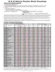
The speed at which the autopilot automatically changes from LO<br />
to HI parameters (or opposite) is determined by the "Transition<br />
Speed" set in the Installation Setup Menu (Sea trial). See<br />
diagram below.<br />
Legend<br />
HI-A High response parameters set automatically<br />
LO-A Low response parameters set automatically<br />
HI-M High response parameters set manually<br />
LO-M Low response parameter set manually<br />
<strong>20221560B</strong> 21
Simrad <strong>AP16</strong> Autopilot<br />
26<br />
24<br />
22<br />
20<br />
18<br />
16<br />
14<br />
12<br />
10<br />
8<br />
6<br />
4<br />
2<br />
0<br />
Speed<br />
HI response parameters<br />
LO response parameters<br />
Transition to LO parameters<br />
with increasing speed: 10 Knots<br />
Transition Speed set to 9 Knots<br />
Transition to HI parameters<br />
with decreasing speed: 8 Knots<br />
Sailboat<br />
When sailing in WIND mode, the parameters are automatically<br />
changed by the direction of the wind as per below or by the boat<br />
speed.<br />
The transition between HI and LO parameters and vice versa<br />
will have a different characteristics with regards to the wind<br />
angle compared with the transition controlled by the speed of the<br />
boat.<br />
If you loose too much speed e.g. when tacking, the parameters<br />
will change to HI to gain sufficient rudder response. This should<br />
be observed when setting the transition speed on sailboats.<br />
2.9 <strong>Manual</strong> Parameter Selection<br />
<strong>Manual</strong> selection of steering parameters is necessary if there is<br />
no speed input to the autopilot or if you want to override the<br />
automatic control.<br />
22 <strong>20221560B</strong>
Operation<br />
To toggle between LO and HI parameters, press the "AUTO"<br />
button two times quickly.<br />
A AUTO<br />
Quick<br />
double<br />
press<br />
Notes !<br />
1. If you are in NAV or WIND modes you need not enter AUTO<br />
mode to manually change the parameter set. Just make a<br />
quick double press on the AUTO button.<br />
2. The manually selected setting (HI or LO) will override the<br />
automatic selection and remain in effect until you re-enter<br />
any automatic mode from STBY.<br />
2.10 U-turn<br />
This feature is very useful in a man overboard situation and<br />
whenever you want to steer back on a reciprocal heading. It only<br />
applies to power boats.<br />
U-Turn changes the current set course to be 180 degrees in the<br />
opposite direction. The user must decide whether the U-Turn<br />
should be made to Port or Starboard when bringing the boat on<br />
the new course. U-Turn is activated by a quick press on the<br />
TURN/DODGE button. The <strong>AP16</strong> will continue on the set<br />
course until you press either the PORT or STBD button to select<br />
the direction to make the U-Turn. If you do not press PORT or<br />
STBD within 1 minute, the <strong>AP16</strong> will return to the AUTO mode<br />
and stay on course.<br />
TURN<br />
DODGE<br />
1<br />
Press<br />
TURN/DODGE<br />
to enter TURN<br />
mode<br />
Select<br />
STBD<br />
U-turn<br />
Boat<br />
makes<br />
STBD<br />
U-turn<br />
<strong>20221560B</strong> 23
Simrad <strong>AP16</strong> Autopilot<br />
2.11 Dodge in AUTO<br />
Dodging is useful in situations where you need to quickly take<br />
control of the helm to steer around an obstruction, and then<br />
resume the previous set heading. Dodging is activated by a quick<br />
double press on the TURN/DODGE button.<br />
When in DODGE mode the displayed set course is the last one<br />
set prior to activating the dodge function. When DODGE is<br />
displayed, the <strong>AP16</strong> is no longer in control of the steering, and<br />
you must either manually steer the boat in STBY mode or take<br />
control using Non Follow Up steering. On manual steering<br />
(STBY mode) the clutch or bypass valve in the drive unit will be<br />
disengaged. The <strong>AP16</strong> will remain in the DODGE mode until<br />
you exit DODGE by a second press on the TURN/DODGE<br />
button or select a mode.<br />
DO TUR TURN<br />
DODGE<br />
Quick double press on<br />
TURN/DODGE<br />
to activate Dodge mode<br />
Perform dodging in one of the following ways:<br />
1. <strong>Manual</strong>ly steer the boat<br />
by the wheel:<br />
2. Non Follow Up steering<br />
by pressing:<br />
or<br />
To return from Dodge mode, press one of the following:<br />
1<br />
1<br />
or using NFU<br />
steering lever<br />
Note !<br />
TURN<br />
DODGE<br />
Selects AUTO<br />
mode and<br />
returns to the<br />
last set course<br />
or<br />
AUTO<br />
Selects AUTO<br />
mode with the<br />
current heading as<br />
the set course<br />
Using NFU mode while dodging will make “NFU” flash instead<br />
of “DODGE”.<br />
24 <strong>20221560B</strong>
Operation<br />
2.12 Tacking in Auto mode<br />
The tack function is only available in sailboats when the system<br />
is set up for SAIL boat type in the installation setup.<br />
Tacking in AUTO mode is different from tacking in WIND<br />
mode. In AUTO mode the tack angle is fixed and can be set in<br />
the Installation/Dockside menu. Default tack angle is 100°.<br />
Tacking should only be performed into the wind and must be<br />
tried out in calm sea conditions with light wind to find out how it<br />
works on your boat. Due to a wide range of boat characteristics<br />
(from cruising to racing boats) the performance of the tack<br />
function may vary from boat to boat. Except for the fixed course<br />
change and the difference in displays, the procedure is similar to<br />
that of the U-Turn described on page 23.<br />
TURN<br />
DODGE<br />
1<br />
Press<br />
TURN/DODGE to<br />
enter TACK mode<br />
2.13 Navigating with the <strong>AP16</strong><br />
Select<br />
STBD<br />
tack<br />
Boat<br />
makes<br />
STBD<br />
tack<br />
The <strong>AP16</strong> has the capability to use steering information from an<br />
external navigator (GPS, Chart Plotter) to direct the boat to a<br />
specific waypoint location, or through a route of waypoints. In<br />
the NAV mode, the <strong>AP16</strong> uses the compass as heading source<br />
for course keeping. The information received from the navigator<br />
alters the set course to keep the boat on the track line and direct<br />
the <strong>AP16</strong> to the destination waypoint.<br />
Note !<br />
Navigational steering should only be used in open waters. By<br />
selecting the NAV mode, the <strong>AP16</strong> is set for automatic steering<br />
on the current set course and then waits for the user to accept<br />
the course change to the track line or destination waypoint.<br />
To obtain satisfactory navigation steering, the following points<br />
must be fulfilled prior to entering the NAV mode:<br />
− The <strong>AP16</strong> autosteering must be tested and determined<br />
satisfactory.<br />
<strong>20221560B</strong> 25
Simrad <strong>AP16</strong> Autopilot<br />
Note !<br />
Note !<br />
NAV<br />
− The navigation receiver (GPS, Chart Plotter) must be in full<br />
operating mode with adequate signal characteristics for valid<br />
position and navigation data.<br />
− At least one waypoint must be entered and selected as the<br />
current “Go to” waypoint.<br />
− The navigation receiver (source) for the autopilot will be the<br />
one that is automatically selected in the interface set-up or<br />
manually selected in the User setup menu item called “Source<br />
select” (page 41).<br />
The <strong>AP16</strong> is designed to steer in “mixed mode” operation. This<br />
combines the straight steering capability of cross track error<br />
(XTE) steering in conjunction with the turning capability of<br />
bearing mode steering (Course To Steer, CTS) and automatic<br />
waypoint shift.<br />
If the <strong>AP16</strong> is connected to a navigation receiver that does not<br />
transmit a message with bearing to next waypoint, it will pick a<br />
XTE message and steer on Cross Track Error only. In that case<br />
you have to revert to AUTO mode at each waypoint and<br />
manually change set course to equal bearing to next waypoint<br />
and then select NAV mode again.<br />
Press the NAV button to activate the NAV prompt display.<br />
The prompt display shows the name of<br />
the next waypoint (WP), the bearing of<br />
the track line (BWW) from the<br />
previous waypoint to the destination<br />
waypoint, the required course change<br />
(CHG) and the direction in which the<br />
boat will turn.<br />
If only one waypoint has been entered the bearing will be from<br />
the present position to the destination waypoint.<br />
Press the NAV button again to accept the waypoint as the<br />
location to steer towards. The autopilot turns the boat onto the<br />
track line.<br />
26 <strong>20221560B</strong>
Operation<br />
Note !<br />
Note !<br />
NAV<br />
NAV<br />
STBY<br />
− NAV mode<br />
− Course to steer (CTS): 353 is set<br />
internally by the autopilot to steer<br />
the boat onto the track line.<br />
− Cross track error (XTE): 0.012 nm<br />
to stbd.<br />
− Compass heading: 352° M.<br />
− Rudder angle: 00°<br />
For Cross Track Error, the number of decimals shown depends<br />
on the output from the GPS/chart plotter. Three decimals give a<br />
more accurate track keeping.<br />
When operating the <strong>AP16</strong> in NAV mode to steer through a route<br />
of waypoints, the <strong>AP16</strong> will steer to the first waypoint in the<br />
route after you accept the first waypoint as the location to steer<br />
towards. When you arrive at the waypoint, the <strong>AP16</strong> will output<br />
an audible warning, display an alert screen with the new course<br />
information, and automatically change course onto the new leg.<br />
If the required course change is more than 10°, you will need to<br />
verify that the upcoming course change is acceptable. This is a<br />
safety feature.<br />
Alert screen. Press NAV button to<br />
verify course change larger than 10°.<br />
If no verification is received, the <strong>AP16</strong><br />
will continue on the current set course<br />
in AUTO mode.<br />
Regain manual steering by pressing the STBY button<br />
Setting the waypoint arrival circle<br />
For route navigation it is recommended to use automatic<br />
waypoint shift/change at a set waypoint arrival circle.<br />
The arrival circle should be adjusted according to boat speed.<br />
The higher speed, the wider circle. The intention is to make the<br />
autopilot start the heading change in due time to make a smooth<br />
turn onto the next leg.<br />
<strong>20221560B</strong> 27
Simrad <strong>AP16</strong> Autopilot<br />
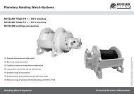
The figure below may be used to select the appropriate waypoint<br />
circle on the GPS/chartplotter.<br />
Note !<br />
Example: With the speed of 20 knots you should use a waypoint<br />
circle with radius 0.09 nm.<br />
The distance between any waypoints in a route must not be<br />
smaller than the radius of the waypoint arrival circle when using<br />
automatic waypoint shift.<br />
2.14 Dodge in NAV<br />
The previous set course is stored by the <strong>AP16</strong>. When DODGE is<br />
flashing on the display, the <strong>AP16</strong> is no longer in control of the<br />
steering and you must either steer the boat manually or take<br />
control using the Non-Follow-up steering. On manual steering,<br />
the clutch (or bypass valve) in the drive unit will be disengaged<br />
when dodging. The <strong>AP16</strong> will remain in the DODGE mode until<br />
you exit DODGE by a second press on the TURN/DODGE<br />
button or until you select another mode.<br />
28 <strong>20221560B</strong>
Operation<br />
DO<br />
TUR TURN<br />
DODGE<br />
Quick double press on<br />
TURN/DODGE<br />
to activate Dodge mode<br />
Perform dodging the same way as in AUTO mode above.<br />
To return from Dodge mode, press one of the following:<br />
TURN<br />
1. DODGE<br />
2. NAV<br />
Returns to NAV mode at present position with<br />
new bearing to waypoint prompt. Keeps all offset<br />
estimates (Wind/current etc.) in the algorithms<br />
(recommended).<br />
Selects NAV mode at present position with new<br />
bearing to waypoint prompt.<br />
3. AUTO<br />
Selects AUTO mode with the current heading as<br />
the set course.<br />
2.15 Selecting a different Navigation source<br />
If you have more than one navigation source connected to the<br />
<strong>AP16</strong>, you will be able to choose any for navigation. Refer to the<br />
‘Source Select’ item in the User Set-up menu for details on<br />
selecting a different navigator (page 41).<br />
2.16 Wind vane steering<br />
Prior to entering WIND mode the <strong>AP16</strong> system should be<br />
operating in AUTO, with valid input from the selected wind<br />
transducer. The WIND mode is only available if the system has<br />
been set up for SAIL-boat in the Installation Menu, and the<br />
NAV/WIND source is set to WIND under the USER SETUP<br />
menu. (Refer to page 38).<br />
Enter the WIND mode by pressing the NAV/WIND button.<br />
The set course to steer (CTS) and set wind angle are entered<br />
from the compass heading and the wind transducer at the<br />
<strong>20221560B</strong> 29
Simrad <strong>AP16</strong> Autopilot<br />
Note !<br />
STBY<br />
moment the WIND-mode is selected. From that point the<br />
autopilot will change the course to maintain the wind angle as<br />
the wind direction may change.<br />
If the cumulative shift of the wind direction exceeds a set limit<br />
from the time a new wind angle is set, a WIND SHIFT alarm will<br />
sound.<br />
The display will show the set wind angle. Adjustments to this set<br />
angle can be made by using the course knob or PORT or STBD<br />
buttons.<br />
The display also presents heading and rudder angle.<br />
Wind (vane) mode<br />
Set wind angle:<br />
044 degrees from stbd.<br />
Measured wind angle: 041°A<br />
A = Apparent<br />
T = True<br />
Parameter: HI-M (High value,<br />
manually set)<br />
Compass reading: 311° M<br />
(magnetic) or T (true)<br />
Rudder angle: 01° to port.<br />
Steer port,<br />
1°/push<br />
1 10 10 1<br />
Steer port,<br />
10°/push<br />
Steer stbd.<br />
10°/push<br />
Regain manual steering by pressing the STBY button<br />
Steer stbd.<br />
1°/push<br />
30 <strong>20221560B</strong>
Operation<br />
2.17 Tacking in Wind mode<br />
In WIND mode there is a tacking and gibing aid function.<br />
Tacking in WIND mode as compared to AUTO mode can be<br />
performed when sailing with apparent or true wind as the<br />
reference, and with a true wind angle of less than 90 degrees.<br />
The tacking operation will immediately mirror the set wind angle<br />
to the opposite side. A tacking-message will flash on the display<br />
for 5 seconds. Any new command given when the message is<br />
flashing, will interrupt the tack operation. The rate of turn during<br />
the tack will be given by the ‘Tack time’ parameter set in the<br />
Installation/Dockside menu (page 90).<br />
A quick press on the TURN/DODGE button will activate the<br />
tack function and the boat will start turning to the same apparent<br />
wind angle on the other side.<br />
<strong>20221560B</strong> 31
Simrad <strong>AP16</strong> Autopilot<br />
Gybing<br />
Gybing is possible when the true wind angle is larger than 120°<br />
When a gybe is initiated, the<br />
wind angle will first be set to<br />
170°T on the same side as the<br />
current wind angle. The main<br />
sail should now be hauled.<br />
With the main sail safely<br />
hauled, the wind side may be<br />
changed. This is done by<br />
pressing either PORT or<br />
STBD buttons depending on<br />
the way the boat should<br />
continue to turn. The new set<br />
wind angle will then become<br />
the same as the wind angle set<br />
before the gybe operation<br />
started.<br />
The rate of turn when changing wind side in a gybe will be the<br />
highest possible, determined by the performance of the drive<br />
unit.<br />
Tack and gybe prevent<br />
When beating and running, the sailing is the most critical.<br />
If the sails are unbalanced when beating, yaw forces from the<br />
sails can drive the boat into the wind. If the boat is driven<br />
beyond the minimum wind angle, the thrust from the sails will<br />
suddenly disappear and the boat speed reduced. Then the boat<br />
will be even more difficult to steer because the rudder will<br />
become less effective.<br />
The tack prevent function in WIND-mode has been implemented<br />
to avoid such situations. It will react immediately when the<br />
apparent wind angle becomes 5° less than the set minimum wind<br />
angle. Additional amount of rudder will be commanded to<br />
immediately increase the wind angle.<br />
When running, it is difficult to steer the boat with waves coming<br />
sideways or from behind. The waves may yaw the boat so that<br />
32 <strong>20221560B</strong>
Operation<br />
the wind side is shifted and an unwanted gybe may happen. This<br />
can be hazardous for both the crew and the mast.<br />
The gybe prevent function will be activated when the measured<br />
apparent wind angle becomes greater than 175° or when the<br />
wind angle gets opposite to the set wind angle. Additional rudder<br />
will be commanded to keep the wind on the same side as the set<br />
wind angle.<br />
Caution !<br />
The tack and gybe prevent functions are not a guarantee<br />
against getting into a hazardous situation. If the effect of the<br />
rudder and/or drive unit is not adequate, it may happen. Pay<br />
particular attention in such situations.<br />
2.18 Wind steering and navigation<br />
The autopilot can also steer the boat given both wind data and<br />
track data from a GPS/Chartplotter. In this mode called<br />
WIND NAV mode the automatic steering is based on a set of<br />
criteria (see bullets below). Wind steering and navigation is<br />
activated by pressing the NAV/WIND button when in Wind<br />
mode. There are two sub-modes under this key: NORMAL<br />
(default) and RACING (see below). The initial course change<br />
(CHG) needed to navigate towards the active waypoint, is<br />
calculated by the autopilot. The autopilot will maintain windside<br />
in these calculations and the change of course is accepted by<br />
pressing the PORT or STBD buttons [1].<br />
<strong>20221560B</strong> 33
Simrad <strong>AP16</strong> Autopilot<br />
[1] [2] [4] [3] [7]<br />
[5] [6] [8]<br />
Figure 2-2<br />
34 <strong>20221560B</strong>
Operation<br />
Operating in WIND NAV mode<br />
Refer to Figure 2-2 with references [ ] the associated displays<br />
and the criteria (bullets) below.<br />
• The set wind angle should be larger than the ‘Minimum<br />
wind angle’ set in the Installation/Dockside menu and<br />
smaller than 170° Apparent.<br />
• Information about when it is time to head directly towards<br />
the waypoint, Distance To Turn (DTT) and Estimated Time<br />
to Turn (ETT) are displayed. These calculations are based on<br />
the assumption that the set wind angle will be the same or<br />
larger after a tack or gybe towards the waypoint [3][7].<br />
• A turn prompt will appear when it is time to head towards<br />
the waypoint and the autopilot will calculate and display the<br />
change of heading by comparing the current heading and the<br />
heading towards the waypoint (CHG) [5].<br />
• When heading towards the waypoint, the autopilot utilizes<br />
either the XTE from the GPS/Chartplotter to maintain track<br />
or a layline calculated by the autopilot. The calculated<br />
layline applies when the Cross Track Error (XTE) from the<br />
external navigator is larger than 0.15 nm [8].<br />
RACING<br />
If ‘Wind setup’ is set to ‘RACING’ in the Installation/Dockside<br />
menu, a more advanced steering is possible:<br />
• Optimising VMG to wind may be enabled when beating and<br />
it is not possible to head directly towards the waypoint [2][4].<br />
• Layline steering may be disabled when heading directly<br />
towards the waypoint. Instead you can optimise the Waypoint<br />
Closure Velocity (WCV) by trimming the sails and the set<br />
wind angle. A turn prompt will then be displayed if the<br />
difference between Course Over Ground (COG) and Bearing<br />
Position Waypoint (BPW) exceeds 30° when heading<br />
towards a waypoint [5].<br />
See chapter 2.21 User Set-up Menu on how to access these<br />
parameters.<br />
<strong>20221560B</strong> 35
Simrad <strong>AP16</strong> Autopilot<br />
2.19 Multiple station system<br />
In normal operation control is accessible from every control unit<br />
connected to the <strong>AP16</strong> system. One control unit is "active" and<br />
provides the user with access to all functions. All remaining<br />
control units are "inactive" and have no effect on mode changes<br />
or course selection. A single press on any of the mode buttons on<br />
an "inactive" control unit will allow transfer of command and<br />
make it "active".<br />
2.20 Lock function<br />
The "LOCK" function is a safety feature included in the <strong>AP16</strong><br />
system. It will disable all control units except for a single, user<br />
selected control unit location.<br />
When the "lock" function is in use, no transfer of command can<br />
take place; only the active control unit stays in command.<br />
To enable the "lock" function, make a quick double press on the<br />
STBY button.<br />
S STBY<br />
The display on the active control unit will first show a<br />
and then the icon will alternate with the mode index.<br />
The "locked" control units in the system will show:<br />
icon<br />
36 <strong>20221560B</strong>
Operation<br />
The “Lock function is disengaged by one of the following<br />
actions:<br />
− The active control unit unlocks the other ones and makes<br />
them “inactive” by another double press on the STBY<br />
button. It also displays the icon before it returns to the<br />
normal active state.<br />
− The system is switched OFF by any control unit (press<br />
STBY for 2-3 seconds).<br />
2.21 User Set-up Menu<br />
INFO<br />
INFO<br />
SE<br />
SETUP<br />
In the <strong>AP16</strong>, all modes except NFU have a complemental<br />
User Set-up menu. You can easily access the set-up menu<br />
by a quick double press on the INFO/SETUP button.<br />
1 1<br />
10 10<br />
Quick double press<br />
to access<br />
Scroll through the menu<br />
Change a value or<br />
setting<br />
Alternating Course Knob Icon<br />
When the PORT 10 and STBD 10 buttons are used in the<br />
User Set-up menu, an icon will alternate with the mode<br />
index to tell that no course changes can be made unless you<br />
press the mode button.<br />
The user set-up menu times out 30 seconds after the last<br />
operation in the menu.<br />
<strong>20221560B</strong> 37
Simrad <strong>AP16</strong> Autopilot<br />
STANDBY Mode<br />
Backlight<br />
The backlight of the display and buttons may be<br />
adjusted to 10 levels (10 = brightest). The setting is<br />
stored when the system is turned off. Adjustment is<br />
local to the control unit you adjust or synchronized with<br />
other units in the Simrad Group (page 107).<br />
Contrast<br />
The contrast of the display may be adjusted to 10 levels<br />
(10 = highest contrast). The setting is stored when the<br />
system is turned off.<br />
Adjustment is local to the control unit you adjust. At<br />
high temperatures, not all levels are available due to<br />
automatic temperature compensation.<br />
Nav/Wind<br />
This parameter will only be available if ‘Boat type’ is<br />
set to ‘Sail’ in the Installation/Dockside menu (see<br />
Dockside settings, page 83). The ‘Nav/Wind’ parameter<br />
will configure the active mode on the NAV/WIND<br />
button. The following alternatives are available:<br />
• NAV<br />
• WIND Auto<br />
Wind steering will be disabled when the ‘Nav/Wind’ parameter<br />
is set to ‘NAV’. Then the normal NAV mode for power boats is<br />
activated when pressing the NAV/WIND button.<br />
If ‘Nav/Wind’ is set to ‘WIND Auto’, wind<br />
steering will be enabled. Pressing the<br />
NAV/WIND button will then initiate the WINDmode.<br />
The autopilot will automatically select<br />
between apparent and true wind steering.<br />
True wind steering is used when running. When the boat is<br />
running, it will also be surfing on the waves. This may lead to<br />
significant changes in boat speed, hence changes in apparent<br />
wind angle. Steering to apparent wind is therefore used only<br />
when beating or reaching.<br />
Range: NAV, WIND Auto<br />
Default: WIND Auto<br />
38 <strong>20221560B</strong>
Operation<br />
Nav/Wind, RACING parameters<br />
If ‘Wind setup’ is set to ‘RACING’ in the Installation/Dockside<br />
menu (see page 88), more settings are available under the<br />
‘Nav/Wind’ parameter:<br />
• NAV<br />
• WIND Apparent<br />
• WIND True<br />
• WIND Auto<br />
Default: WIND Auto<br />
‘WIND Apparent’ is selected when you only want to steer to<br />
apparent wind. Apparent wind steering is preferred when you<br />
want to achieve maximum boat speed. The autopilot will try to<br />
maintain a constant apparent wind angle to get maximum thrust<br />
from a given trim of the sails.<br />
‘WIND True’ is selected when you only want to steer to true<br />
wind. When sailing in closed waters, the apparent wind angle<br />
may change temporarily due to wind gusts. It may then be<br />
preferred to sail to the true wind.<br />
VMG Optimizing<br />
The VMG (to wind) parameter can only be enabled<br />
or disabled when ‘Wind setup’ is set to ‘RACING’.<br />
It is disabled in the ‘NORMAL’ sub-mode.<br />
When enabled, the VMG optimizing will be active<br />
for 5 – 10 minutes after a new wind angle has been<br />
set. It will only be activated when beating.<br />
‘VMG’ will be displayed in the upper left corner under the mode<br />
index when the VMG optimizing feature is active (page 34).<br />
Range: Enabled/Disabled<br />
Default: Disabled<br />
<strong>20221560B</strong> 39
Simrad <strong>AP16</strong> Autopilot<br />
Layline Steering<br />
‘Layline steering’ can only be enabled or disabled<br />
when ‘Wind setup’ is set to ‘RACING’. It is<br />
enabled in the ‘NORMAL’ sub-mode. .<br />
Layline steering is useful when navigating. It will use the Cross<br />
Track Error (XTE) from the navigator to keep the boat on the<br />
track line. If the XTE from the navigator exceeds 0.15 nm, the<br />
autopilot will calculate its own layline towards the waypoint and<br />
follow that. Layline steering is not active when turning, tacking<br />
or gybing.<br />
‘XTE’ will be displayed in the upper left corner under the mode<br />
index when layline steering is active (page 34).<br />
Range: Enabled/Disabled<br />
Default: Enabled<br />
Instrument Select<br />
Select the instrument page(s) to be available under<br />
the INFO/SETUP button. Step through the list of<br />
instrument pages by using the PORT 1 or STBD 1<br />
button. Select the wanted pages by filling the<br />
squares with the PORT 10 or STBD 10 button.<br />
Available instrument pages are: Depth/Speed, Wind<br />
App., Wind True, Wind Dir., Track data, Nav data,<br />
Position and Temperature.<br />
40 <strong>20221560B</strong>
Operation<br />
Notes !<br />
Source Select<br />
Provides you with automatic or manual selection of<br />
interfaced data sources for heading (Compass),<br />
Navigation, Position, Wind Angle, Wind Calculated,<br />
Water speed, Water temperature, Distance log and<br />
Depth.<br />
Wind-C(alculated) is a common term for true wind and<br />
wind direction.<br />
Auto source update<br />
Is used for automatic selection of the interfaced sources<br />
or for automatically update of sources if the interfaced<br />
units have been removed/added or switched on/off.<br />
Select Auto source update by pressing the STBD 10<br />
button. Make sure all interfaced units are powered on.<br />
The autopilot will search for new connected sources, and<br />
replace sources no longer available.<br />
“SEARCHING” is flashing as long as the autopilot is<br />
searching. When the automatic interface setup is finished<br />
the display will read “DONE”.<br />
Press the mode button to leave the User setup.<br />
<strong>Manual</strong> select<br />
Step through the list of sources using the PORT 1 or STBD 1<br />
button. Select the wanted source by using the PORT 10 or<br />
STBD 10 button.<br />
– – indicates that no source is supplying the data available.<br />
1. Simrad products will be identified by the product name<br />
provided the data is available on SimNet. If data is<br />
provided via an NMEA0183 port on the autopilot<br />
computer, the display will read NMEA-1 or NMEA-2.<br />
NMEA2000 products will have a special ID.<br />
2. See note on page 71 and note 3 below.<br />
3. In the event the SimNet is not powered on, sources<br />
supplying data to SimNet are not on or malfunctioning, or<br />
there is no SimNet installed, it is possible to use any<br />
control unit in the system to select NMEA sources. .The<br />
source select displays are then available on all control<br />
units.<br />
<strong>20221560B</strong> 41
Simrad <strong>AP16</strong> Autopilot<br />
Compass<br />
Select the compass to be used if more than one compass is<br />
connected.<br />
Navigation<br />
Select the source for navigational data.<br />
Position<br />
Select the source for position data.<br />
Wind Angle<br />
Select the source for Wind Angle.<br />
Wind Calculated<br />
Select the source for Calculated Wind data. The autopilot<br />
uses internal source irrespective of the selected source.<br />
Water Speed<br />
Select the source for water speed (normally the same as the<br />
source providing Log data).<br />
Water temperature<br />
Select the source for water temperature (normally the same<br />
as the source providing depth data).<br />
DisLog<br />
Select the Log source.<br />
Depth<br />
Select the source for depth data.<br />
Press the STBY button to leave the User setup.<br />
42 <strong>20221560B</strong>
Operation<br />
AUTO Mode<br />
Settings that are added for the AUTO and WIND modes are<br />
shown below. Other relevant settings are described under<br />
STANDBY mode in this chapter.<br />
Seastate filter<br />
OFF: Seastate filter is disabled.<br />
AUTO: Automatically reduces rudder activity and<br />
autopilot sensitivity in rough weather by<br />
an adaptive process (default).<br />
MANUAL: <strong>Manual</strong> yaw band adjust (1-10, 10 ≈ ±6°).<br />
The manual setting determines the number of degrees the vessel<br />
may deviate from the set course before any command is given to<br />
the rudder. The AUTO setting is recommended. The MANUAL<br />
settings may be used to find the optimum combination of course<br />
keeping and low rudder activity in rough but steady sea<br />
conditions.<br />
Response<br />
The Autotune function in the <strong>AP16</strong> is so refined that 80-85 % of<br />
the boats will need no further adjustments of the steering<br />
parameters. On some boats, however, or at particular sea<br />
conditions a fine tuning of the steering parameters may improve<br />
the performance of the autopilot.<br />
The Response control allows you to make this fine<br />
tuning. It can be set to seven levels. Level 3 (default)<br />
has the values of Rudder and Counter Rudder<br />
parameters set by the Autotune function. If no<br />
Autotune is made (not recommended) the level 3<br />
values are the factory default values.<br />
A low response level reduces the rudder activity and provides a<br />
more “loose” steering.<br />
A high response level increases the rudder activity and provides<br />
a more “tight” steering.<br />
A too high response level will make the boat start S-ing.<br />
Range: 1 – 7<br />
Default: 3<br />
<strong>20221560B</strong> 43
Simrad <strong>AP16</strong> Autopilot<br />
NAV Mode<br />
The User setup for NAV mode is identical to the User setup for<br />
AUTO mode.<br />
WIND Mode<br />
The User setup for WIND mode includes the<br />
same functions as the User setup for AUTO<br />
mode. In addition you have the:<br />
Note !<br />
Wind response<br />
If the deviation between the commanded wind angle and<br />
measured wind angle is too big, the ‘Wind response’ can be<br />
increased to reduce the deviation.<br />
First make sure that the deviation between the Course To Steer<br />
(CTS) and the measured heading is minimal.<br />
If the measured wind angle is S-ing around the commanded wind<br />
angle or the rudder activity is too high, the ‘Wind response’<br />
should be reduced.<br />
Range: 1 – 7<br />
Default: 3<br />
44 <strong>20221560B</strong>
Operation<br />
2.22 INFO menu<br />
A number of instrument pages are available under each mode<br />
screen if the required NMEA 0183 sentences are provided (see<br />
paragraph 8.1) or the information is available on SimNet (see<br />
page 107). The INFO menu is accessed by a single press on the<br />
INFO/SETUP button (not necessary if the unit is inactive).<br />
The top of the screen will show the following information<br />
depending on the active mode:<br />
Standby mode<br />
Heading<br />
Auto mode<br />
Set course<br />
HI/LO parameter<br />
Heading<br />
Nav mode<br />
HI/LO parameter<br />
Cross Track Error<br />
Wind mode<br />
HI/LO parameter<br />
Set apparent wind angle<br />
Step through the available instrument screens by pressing the<br />
PORT or STBD button.<br />
Depth/Speed<br />
Depth<br />
Speed through water<br />
Speed Over Ground<br />
Apparent wind<br />
Wind angle<br />
Wind Speed<br />
Rudder angle<br />
<strong>20221560B</strong> 45
Simrad <strong>AP16</strong> Autopilot<br />
True wind<br />
Wind angle<br />
Wind Speed<br />
VMG to wind<br />
Wind direction<br />
True wind speed<br />
Wind shift angle<br />
Track data<br />
Waypoint name<br />
Bearing Position – Waypoint<br />
Cross Track Error<br />
Nav data<br />
Waypoint name<br />
Bearing Position – Waypoint<br />
Course Over Ground<br />
Distance to waypoint<br />
Position<br />
Latitude<br />
Longitude<br />
Sea Temperaure<br />
If you prefer not to have all instrument pages available in the<br />
INFO menu, you may remove pages under the User setup menu.<br />
See page 37.<br />
Return to last instrument screen by a simple press on the<br />
INFO/SETUP button.<br />
46 <strong>20221560B</strong>
Operation<br />
Course knob icon<br />
Initially when the INFO menu is accessed an icon will replace<br />
the mode index to tell that no course changes or other course<br />
related settings can be made unless you press a mode key. The<br />
icon will time out after 3-5 seconds and be replaced by the<br />
mode index.<br />
INFO menu flowchart<br />
1<br />
1<br />
11<br />
12<br />
1<br />
10<br />
2<br />
9<br />
8<br />
7<br />
6<br />
3<br />
4<br />
5<br />
3-5 sec.<br />
time-out<br />
Toggle<br />
1<br />
3-5 sec.<br />
time-out<br />
10<br />
11<br />
12<br />
1<br />
2<br />
1<br />
9<br />
3<br />
8<br />
4<br />
7<br />
6<br />
5<br />
<strong>20221560B</strong> 47
Simrad <strong>AP16</strong> Autopilot<br />
INFO menu and Main screen active unit<br />
INFO-menu<br />
Main screen<br />
10<br />
10<br />
1<br />
1<br />
12<br />
11<br />
10<br />
9<br />
8<br />
7<br />
6<br />
1<br />
2<br />
3<br />
4<br />
5<br />
3-5 sec. time out<br />
Note !<br />
Whenever the INFO menu is active and the mode index is<br />
present on an active unit, operating the PORT and STBD buttons<br />
will immediately make the main screen reappear.<br />
INFO menu and Main Screen, inactive unit<br />
Previous INFO page<br />
1 1<br />
Next INFO page<br />
Last shown INFO page<br />
You can view the INFO pages without activating the unit.<br />
48 <strong>20221560B</strong>
Installation<br />
3 INSTALLATION<br />
3.1 General<br />
This section provides detailed information required to<br />
successfully installing <strong>AP16</strong> Autopilot system.<br />
The <strong>AP16</strong> system includes several modules that need to be<br />
mounted in different locations on the boat, and also need to<br />
interface with at least three different systems on the boat:<br />
− The boat's steering system<br />
− The boats electrical system (input power)<br />
− Other equipment on board (NMEA interfacing)<br />
In addition, the advanced capabilities of the <strong>AP16</strong> require the<br />
installer to perform a series of settings and tests to verify proper<br />
operation of the system, refer to the check list below.<br />
3.2 Installation checklist<br />
1. Determine system configuration you are installing (Page 50)<br />
2. Perform the hardware installation (Page 51)<br />
3. Connect SimNet devices to SimNet (page 66)<br />
4. Connect NMEA2000 devices (page 69)<br />
5. Connect NMEA 0183 devices (inputs and outputs, page 72)<br />
6. Perform Set-up (page 79)<br />
7. Perform dockside autopilot tests (refer to Operating<br />
Instructions, page 15)<br />
a) Test all stations (if applicable) - lock/unlock - active/<br />
inactive<br />
b) Test Non-Follow Up mode<br />
c) Test Follow-Up mode<br />
d) Test AUTO mode<br />
e) Test NAV mode and input interfaces<br />
f) Test WIND and WIND N modes (if sailboat) and input<br />
interfaces<br />
g) Test interface outputs to external equipment (if<br />
connected)<br />
8. Perform sea trial settings (Page 91)<br />
a) Rudder zero<br />
b) Compass calibration<br />
c) Compass Offset adjustment<br />
<strong>20221560B</strong> 49
Simrad <strong>AP16</strong> Autopilot<br />
d) Automatic tuning<br />
e) Viewing parameters<br />
9. Test Autopilot Operation at Sea (refer to Sea Trial<br />
instructions, pages 92, 109)<br />
10. Provide the user with training (Page 110)<br />
3.3 Unpacking and handling<br />
Care should be taken when unpacking and handling the<br />
equipment. A visual inspection should be made to see that the<br />
equipment has not been damaged during shipment and that all<br />
components and parts are present according to the packing list.<br />
A standard <strong>AP16</strong> autopilot system will include:<br />
− Control unit with standard installation accessories and one<br />
15 m (49') Robnet2 cable<br />
− Autopilot computer (AC10, AC20 or AC40)<br />
− RFC35 Fluxgate Compass with 15 m (49') cable attached.<br />
− RF300 Feedback unit with 10 m (33') cable attached and<br />
transmission rod.<br />
− Appropriate drive unit for the installation (unless the <strong>AP16</strong> is<br />
going to operate an existing drive unit or solenoids).<br />
− Optional equipment that may have been ordered for the<br />
installation.<br />
3.4 Determine system configuration<br />
It is important to become familiar with the configuration of the<br />
system prior to beginning the installation. The <strong>AP16</strong> system<br />
layout with options is shown in Figure 3-1<br />
Pay particular attention to the autopilot computer/drive unit<br />
combinations on page 56 and the chart on page 11.<br />
As many of the units are communicating on a common network<br />
(Robnet2), with identical connectors, the installation is<br />
simplified. Try to mount the units within the standard cable<br />
length supplied with each unit, if possible. Robnet2 Extension<br />
Cable (10m) is available from your distributor.<br />
50 <strong>20221560B</strong>
PWR<br />
SETUP<br />
DODGE<br />
PWR<br />
SETUP<br />
TURN<br />
DODGE<br />
STBY AUTO<br />
pfjo^a=oPMMMu<br />
STBY<br />
PWR<br />
NAV<br />
SETUP<br />
AUTO<br />
SPEED<br />
TURN<br />
Installation<br />
3.5 <strong>AP16</strong> System Layout<br />
STBY<br />
AUTO<br />
10 10<br />
STBY<br />
AUTO<br />
10 10<br />
INFO<br />
NAV<br />
WIND<br />
1 1<br />
TURN<br />
INFO<br />
NAV<br />
WIND<br />
1<br />
1<br />
Figure 3-1 <strong>AP16</strong> system layout with options<br />
3.6 RF300 Rudder feedback installation<br />
Note !<br />
The RF300 Rudder feedback unit mounts close to the rudder,<br />
and is mechanically linked to the rudder tiller arm or rudder<br />
quadrant.<br />
Refer to Figure 3-2 for the recommended mounting arrangement.<br />
Note that the RF300 transmitter arm has two slots for the<br />
transmission link. The slots enable maximum flexibility to<br />
provide the 1:1 mechanical linkage relationship.<br />
Do not try to remove the transmitter arm from the feedback unit.<br />
The unit is factory adjusted and need no further adjustment at<br />
installation than described below.<br />
As a starting point, it is desirable to set the transmitter rod to the<br />
inner limit of the outer slot if possible. (Refer to Figure 3-2).<br />
Drill and tap the rudder tiller arm so that the Y1 dimension is<br />
equal to the Y2 dimension (Use 4.2 mm drill and 5 mm tap).<br />
<strong>20221560B</strong> 51
Simrad <strong>AP16</strong> Autopilot<br />
Note !<br />
Attach the ball joint to the tiller arm, and connect the transmitter<br />
rod to the ball joint at the rudder tiller arm.<br />
Turn the helm wheel to set the rudder tiller arm to approximate<br />
centre position.<br />
Rotate the RF300 transmitter lever until it is set to centre<br />
position. (Use the alignment mark to line up the transmitter lever<br />
to be opposite the cable entry into the feedback.).<br />
Carefully observe the alignment marks. A rudder feedback alarm<br />
may be the result if the alignment instructions as per Figure 3-2<br />
are neglected.<br />
Attach the transmitter rod to the RF300. Set the RF300 mounting<br />
location to be in accordance with Figure 3-2. The centre of the<br />
RF300 should be in line with the centre of the rudder post.<br />
Mount the RF300 to a suitable platform using the screws<br />
provided. If necessary, add blocking material under the RF300 to<br />
adjust the height of the transmission arm to be level with the<br />
rudder tiller arm.<br />
Figure 3-2 RF300 mounting (019356)<br />
Note !<br />
Due to space limitations, it may be necessary to cut the length of<br />
the transmitter rod to move the RF300 closer to the rudder post.<br />
Tighten the mounting screws for both the RF300 feedback unit<br />
and the transmitter rod ball joint.<br />
Observe the RF300 while someone turns the helm wheel through<br />
the complete travel from full port to full stbd. rudder to verify<br />
that the mechanical linkage to the RF300 is not obstructed.<br />
52 <strong>20221560B</strong>
Installation<br />
AUTOPILOT COMPUTER<br />
MAIN PCB<br />
RF +<br />
RF<br />
Rudder<br />
Feedb.<br />
*<br />
* NON POLARIZED<br />
(COLOR INDEPENDENT)<br />
Figure 3-3 RF300 connection<br />
3.7 Autopilot computer installation<br />
Note !<br />
The junction unit is<br />
designed to operate in a<br />
location that provides<br />
ambient temperatures<br />
below +55°C (+130°F).<br />
The autopilot computer<br />
units (AC10, AC20 and<br />
AC40) are not<br />
weatherproof and should<br />
be mounted vertically as<br />
shown in a dry place<br />
between the control unit<br />
and the drive unit.<br />
Figure 3-4 Autopilot computer mounting<br />
3.8 Cable connections<br />
Use only shielded cables. This includes Mains input, drive units<br />
and if necessary for the extension of the RF300 Rudder<br />
Feedback cable. The clutch/bypass cable and the solenoid cable<br />
should be 1,5 mm 2 (AWG14). Signal cables should be 0.5 mm 2<br />
(AWG20) twisted pairs.<br />
The mains supply cable and the drive unit motor cable should<br />
have sufficient wire gauge. This will minimize voltage drop and<br />
allow the drive unit to operate at full power.<br />
<strong>20221560B</strong> 53
Simrad <strong>AP16</strong> Autopilot<br />
Refer to the table below for recommended cable sizes.<br />
Cable length<br />
Drive Unit Voltage<br />
1. Breaker panel to autopilot computer. 12 V 24 V<br />
2. Autopilot computer to Drive Unit motor<br />
(Length refers to each of the two cables)<br />
AWG mm 2 AWG mm 2<br />
Up to 3 m (10 ft.) 12 2,5 12 2,5<br />
Up to 6 m (20 ft.) 10 4 10 2,5<br />
Up to 10 m (32 ft.) 8 6 10 4<br />
Up to 16 m (52 ft.) 6 10 8 6<br />
3.9 Grounding and RFI<br />
The autopilot system has excellent RFI protection and all units<br />
use the autopilot computer as a common ground/shield<br />
connection. The autopilot computer should therefore have a<br />
proper ground connection to the hull/bonding system.<br />
Robnet2 cables and other signal cables (compass, feedback,<br />
NMEA) should not be run in parallel with other cables carrying<br />
RF or high current, such as VHF and SSB transmitters, battery<br />
chargers/ generators, winches and thrusters.<br />
Remove the bottom cover to get access to the plug-in terminals.<br />
Strip about 1 cm (0.4") of the cable's insulation and pull the<br />
screen backwards to cover the insulation. Position the straps as<br />
shown and tighten well to make sure the screen has good<br />
contact.<br />
Provide sufficient wire length so that the plug-in terminals can<br />
be easily connected/disconnected.<br />
Pull out each terminal before connecting the wires. Remove all<br />
strands before putting on the terminal cover.<br />
54 <strong>20221560B</strong>
Installation<br />
Note!<br />
The Mains input<br />
is not polarity<br />
protected on<br />
AC40.<br />
Ground terminal<br />
Power Board terminals<br />
TB9 and TB10 are not on the<br />
AC10 Power Board<br />
Main Board terminals<br />
<strong>20221560B</strong> 55
Simrad <strong>AP16</strong> Autopilot<br />
3.10 Drive unit installation<br />
MODEL<br />
MOTOR<br />
VOLTS<br />
The relations between drive units, drive unit voltage, autopilot<br />
computer, drive performance and interface to the steering gear<br />
are shown in the tables below.<br />
Refer to the connecting diagram for the different drive units on<br />
page 58 onwards.<br />
Installation instruction for the drive units are found in the<br />
manual for the individual units.<br />
The maximum drive current capability of the AC10, AC20 and<br />
AC40 autopilot computers are different. Use the table below as<br />
reference and observe the notes on next page.<br />
HYDRAULIC PUMPS<br />
AUTOPILOT<br />
COMPUTER<br />
RAM CAPACITY<br />
MIN<br />
cm 3<br />
(cu. in.)<br />
MAX<br />
cm 3<br />
(cu. in.)<br />
FLOW RATE<br />
AT 10 bar<br />
cm 3 /min<br />
(cu. in/min)<br />
MAX<br />
PRESSURE<br />
bar<br />
PWR.<br />
CONSUM-<br />
PTION<br />
RPU80 12V AC10 80 (4,9) 250 (15,2) 800 (49) 50 2,5-6 A<br />
RPU160 12V AC20 160 (9,8) 550 (33,5) 1600 (98) 60 3-10 A<br />
RPU300 12V AC40 290<br />
(17,7)<br />
960 (58,5) 3000 (183) 60 5-25 A<br />
RPU300 24V AC20 290<br />
(17,7)<br />
960 (58,5) 3000 (183) 60 2,5-12 A<br />
Steering gear interface: Hydraulic plumbing<br />
Notes !<br />
1. The <strong>AP16</strong> system detects whether a reversible motor or a<br />
solenoid is connected and outputs the correct drive signal<br />
automatically.<br />
2. The drive output of AC10 is sufficient for any type of 12 and<br />
24V solenoids normally found on a recreational boat.<br />
56 <strong>20221560B</strong>
Installation<br />
MODEL<br />
MOTOR<br />
VOLTS<br />
AUTO-<br />
PILOT<br />
COM-<br />
PUTER<br />
MAX<br />
STROKE<br />
mm (in.)<br />
LINEAR DRIVE UNITS<br />
PEAK<br />
THRUST<br />
kg (lb.)<br />
MLD200 12V AC10 300 (11,8) 200<br />
(440)<br />
HLD350 12V AC10 200 (7,9) 350<br />
(770)<br />
HLD2000L 12V AC20 340 (13,4) 500<br />
(1100)<br />
HLD2000D 24V AC20 200 (7,9) 1050<br />
(2310)<br />
HLD2000LD 24V AC20 340 (13,4) 1050<br />
(2310)<br />
MSD50* 12V AC10 190 (7,5) 60<br />
(132)<br />
MAX<br />
RUDDER<br />
TORQUE<br />
Nm<br />
(lb.in.)<br />
490<br />
(4350)<br />
610<br />
(5400)<br />
HARD-<br />
OVER<br />
TIME<br />
sec.<br />
(30% load)<br />
PWR.<br />
CON-<br />
SUMP.<br />
TILLER<br />
ARM<br />
mm<br />
(in.)<br />
15 1,5-6 A 263<br />
(10,4)<br />
12 2,5-8 A 175<br />
(6,9)<br />
1460 (12850) 19 3-10 A 298<br />
(11,7)<br />
1800<br />
(15900)<br />
3180<br />
(28000)<br />
Steering gear interface: Connects to quadrant or tiller.<br />
* For stern drive power assisted steering only.<br />
11 3-10 A 175<br />
(6,9)<br />
19 3-10 A 298<br />
(11,7)<br />
– 15 0,8-2 A –<br />
1. The motor voltage is stepped down by the autopilot computer<br />
when operating from 24V or 32V mains.<br />
2. The specified junction unit is necessary to achieve max drive<br />
unit capacity.<br />
3. Recommended operational thrust or torque is 70% of listed<br />
peak value.<br />
4. Typical average power consumption is 40% of listed<br />
maximum value.<br />
<strong>20221560B</strong> 57
Simrad <strong>AP16</strong> Autopilot<br />
PREVIOUS MODELS OF DRIVE UNITS<br />
Model<br />
Autopilot<br />
computer<br />
Drive unit<br />
voltage<br />
Input<br />
voltage<br />
(Mains)<br />
Drive output<br />
Interface to<br />
steering<br />
gear<br />
RPU100 (1,0l)<br />
RPU150 (1,5l)<br />
RPU200 (2,0l)<br />
(Reversible<br />
hydraulic<br />
pump)<br />
AC20<br />
AC20<br />
AC20<br />
12V<br />
12V<br />
24V<br />
12,24,32V<br />
Proportional<br />
rate<br />
Hydraulic<br />
plumbing<br />
RPU1 (1,4/2,0l)<br />
RPU3 (3,8/5,0l)<br />
AC10<br />
AC10<br />
12V, 24V<br />
24V, 24V<br />
Solenoid<br />
valves, on/off<br />
Hydraulic<br />
plumbing<br />
MRD100<br />
(Reversible<br />
mechanical<br />
drive)<br />
MRD150<br />
(USA only)<br />
Note !<br />
AC40<br />
AC20<br />
AC20<br />
12V<br />
24V<br />
12V<br />
32V<br />
12,24,32V<br />
24,32V<br />
12, 24V<br />
32V<br />
12V to clutch<br />
24V to clutch<br />
Proportional<br />
rate to motor<br />
12V to clutch<br />
32V to clutch<br />
Proportional<br />
rate to motor<br />
Chain/<br />
sprockets<br />
Chain/<br />
sprocket<br />
When selecting DRIVE UNIT voltage in the Installation setup,<br />
the clutch/bypass voltage is always set equal to the motor<br />
voltage. If a retrofit installation where e.g. a HLD2000 has a<br />
12V motor and a 24V bypass valve, the bypass valve solenoid<br />
has to be changed back to standard 12V version.<br />
Connecting a reversible pump<br />
AUTOPILOT COMPUTER<br />
POWER PCB<br />
TB1 TB2 TB3 TB4 TB5<br />
TB6<br />
Simrad<br />
reversible<br />
pump<br />
Sol. -Motor<br />
Sol. -Motor<br />
Figure 3-5 Connecting a reversible pump<br />
58 <strong>20221560B</strong>
Installation<br />
Connecting a hydraulic linear drive<br />
HYDRAULIC<br />
LINEAR DRIVE<br />
AUTOPILOT COMPUTER<br />
POWER PCB<br />
TB1 TB2 TB3 TB4 TB5<br />
TB6<br />
TB7<br />
Sol. -Motor<br />
Sol. -Motor<br />
Bypass<br />
Clutch<br />
Single pole<br />
clutch/bypass<br />
switch<br />
Figure 3-6 Connecting a hydraulic linear drive<br />
Connecting a solenoid valve<br />
SOLENOID<br />
VALVE<br />
AUTOPILOT COMPUTER<br />
POWER PCB<br />
TB1 TB2 TB3 TB4 TB5<br />
TB6<br />
TB7<br />
Sol. gnd<br />
Sol. -Motor<br />
Sol. -Motor<br />
Sol.<br />
Sol. gnd<br />
Sol.<br />
Figure 3-7 Connecting a solenoid valve<br />
<strong>20221560B</strong> 59
Simrad <strong>AP16</strong> Autopilot<br />
3.11 Control unit installation<br />
Avoid mounting the control unit(s) where it is easily exposed to<br />
sunlight, as this will shorten the lifetime of the display. If this is<br />
not possible, make sure the units are always covered with the<br />
white protection cover when not used.<br />
Caution !<br />
Do not install the control unit where moisture at the rear can<br />
be present. It could cause damage by entering the breathing<br />
hole or by coming into contact with the electrical connectors.<br />
Panel mounting<br />
The mounting surface must be flat and<br />
even to within 0.5 mm.<br />
− Drill the 4 mounting holes and make<br />
a panel cut-out according to supplied<br />
template.<br />
− Use the supplied gasket (P.N.<br />
22087589) between the panel and the<br />
unit. The gasket should normally be<br />
positioned for rear airing. See text on<br />
gasket. If there is a high humidity in<br />
the room behind the instrument, the<br />
gasket should be positioned for front<br />
airing.<br />
− Use the supplied 19 mm screws to<br />
fasten the control unit to the panel.<br />
− Apply the front panel corners.<br />
− Connect the Robnet2 cable(s) to the control unit connector(s)<br />
Do not over-tighten the mounting screws!<br />
Optional bracket mounting<br />
− Locate the cradle on the mounting site and mark the 4 holes<br />
for the fixing screws on the mounting surface. The bracket<br />
can be mounted as shown on Figure 3-8 or 90° off.<br />
− Drill the 4 mounting holes and screw the cradle to the<br />
mounting surface.<br />
− Use the supplied screws to fasten the control unit to the left<br />
and right brackets.<br />
60 <strong>20221560B</strong>
Installation<br />
− Apply the front panel corners.<br />
− Use the two locking knobs to assemble the cradle with the<br />
left and right brackets and adjust the control head to best<br />
viewing angle.<br />
− Connect the Robnet2 cable(s) to the control unit<br />
connector(s).<br />
Figure 3-8 <strong>AP16</strong> Bracket mounting<br />
3.12 ROBNET2 network cables<br />
As Robnet units have two Robnet2 connectors (blue) they can be<br />
used as "jack points" for further expansion of the system. There<br />
are no dedicated "in" or "out" connectors. You may connect the<br />
cables to any available Robnet2 connector (blue) on the specific<br />
unit. The Robnet2 connectors have a locking mechanism for<br />
extra safety.<br />
Caution !<br />
Do not mix the blue Robnet2 cables with the yellow SimNet<br />
cables.<br />
The 15 m cable to the autopilot computer has a connector only at<br />
the control unit end. Robnet2 cables with 5 pin male connector at<br />
both ends are available in 1, 5 and 10 m length. For cable<br />
extension a Robnet2 T-Joiner is required.<br />
<strong>20221560B</strong> 61
Simrad <strong>AP16</strong> Autopilot<br />
When installing a system, try to minimize total Robnet2 cable<br />
length by connecting all Robnet2 units to the nearest available<br />
Robnet2 connector.<br />
Total length of Robnet2 cable installed in a system should not<br />
exceed 50 m (165').<br />
Examples of interconnecting Robnet2 units:<br />
AUTOPILOT<br />
COMPUTER<br />
CONTROL<br />
UNIT<br />
CONTROL<br />
UNIT<br />
AP27<br />
CONTROL<br />
UNIT<br />
COMPASS<br />
T-joiner<br />
Figure 3-9 Interconnecting Robnet2 units<br />
A Robnet2 T-Joiner P/N 24005662 is available to make the<br />
Robnet2 interconnection more simple by reducing the number of<br />
cables or extend cables when necessary.<br />
See table for pin configuration and colour code of the network<br />
cable.<br />
Cable pairs<br />
1. pair<br />
2. pair<br />
Pink<br />
Grey<br />
Color<br />
code<br />
Brown<br />
White<br />
Yellow<br />
Signal<br />
V SYSTEM+<br />
V SYSTEM–<br />
Bus–<br />
Bus+<br />
On - Off<br />
Figure 3-10 Robnet2 Connector<br />
Note !<br />
The connectors are weather proof according to IP65, when<br />
properly installed. All unused Robnet2 connectors must be fitted<br />
with the plastic cap to protect them against dirt and moisture.<br />
62 <strong>20221560B</strong>
Installation<br />
<strong>AP16</strong><br />
CONTROL UNIT<br />
REAR VIEW<br />
AUTPILOT COMPUTER<br />
MAIN PCB<br />
TB15<br />
On-Off<br />
Vsys<br />
Vsys+<br />
Bus+<br />
Bus<br />
Bn Wh Pnk Gry Yel<br />
ROBNET<br />
Figure 3-11 Control unit connection<br />
J1 and J2 (left) are Robnet2 connectors. J3 and J4 are SimNet<br />
connectors.<br />
Note !<br />
AP27 connection<br />
If a Simrad AP27 is part of the system, use the SimNet connector<br />
in a free receptacle (see Figure 3-9). Alternatively cut the<br />
connector from the cable and connect the wires in parallel with<br />
the cable shown on Figure 3-11 using the same colour code.<br />
The AP27 cable contains an air-breathing tube. Check that the<br />
tube is open after you have cut the cable.<br />
3.13 RFC35 Fluxgate Compass installation<br />
Figure 3-12<br />
RFC35 mounting<br />
<strong>20221560B</strong> 63
Simrad <strong>AP16</strong> Autopilot<br />
Note !<br />
Note !<br />
The heading sensor is the most important part of the <strong>AP16</strong><br />
system and great care should be taken when deciding the<br />
mounting location. As the heading is displayed on the <strong>AP16</strong><br />
Control Unit, the heading sensor can be mounted at a remote<br />
location.<br />
The RFC35 compass can be mounted on deck or bulkhead,<br />
athwartship or alongship. The heading offset feature in the <strong>AP16</strong><br />
will compensate for the mechanical offsets that may be a result<br />
of the selected location and orientation of the RFC35.<br />
If the RFC35 is deck or bulkhead mounted athwartship with the<br />
cable gland pointing aft, little if any offset correction is required.<br />
With the cable gland pointing forward a 180° correction is<br />
required.<br />
When mounting RFC35 on a bulkhead alongship, a +90° or –<br />
90° correction is needed dependent on whether it is port or<br />
starboard bulkhead.<br />
Offset correction is performed after the calibration (see<br />
paragraph 4.6).<br />
Find a location that provides a solid mounting place free from<br />
vibration, and as close to the vessel's centre of roll and pitch as<br />
possible, i.e. close to the water line. It should be as far as<br />
possible from disturbing magnetic influences such as the engines<br />
(min. 2 meters), engine ignition cables, other large metal objects<br />
and particularly the drive unit. On steel hull boats it should be<br />
mounted 0,75-1 m above the wheel house on a non magnetic<br />
stand.<br />
Use the supplied mounting kit and drill the holes through the<br />
centre of the slots in the sensor or the mounting brackets.<br />
The compass face plate on the RFC35 is the TOP. Never mount<br />
it upside down! Level the sensor as close to horizontal as<br />
possible.<br />
Connect the RFC35 to the autopilot computer as per Figure<br />
3-13<br />
64 <strong>20221560B</strong>
Installation<br />
RFC35<br />
FLUXGATE<br />
COMPASS<br />
AUTOPILOT COMPUTER<br />
MAIN PCB<br />
HS-<br />
HS+<br />
Heading<br />
Sensor<br />
* * NON POLARIZED<br />
(COLOR INDEPENDENT)<br />
Figure 3-13 RFC35 connection<br />
3.14 RC36 Rate Compass installation<br />
(Optional)<br />
The RC36 Rate Compass also contains a magnetic heading<br />
sensor, which means you have to take the same precautions at<br />
installation as for the standard RFC35 (see previous page).<br />
Plug the RC36 into a Robnet2 connector (see Figure 3-9) or cut<br />
the connector from the cable and connect the wires in parallel<br />
with the cable shown in Figure 3-11<br />
3.15 R3000X Remote Control installation<br />
R3000X should be mounted in the supplied bracket that can be<br />
fixed by four mounting screws. The unit is weather proof and<br />
can be mounted outdoor.<br />
R3000X<br />
REMOTE CONTROL<br />
AUTOPILOT COMPUTER<br />
POWER PCB<br />
TB1 TB2 TB3 TB4 TB5<br />
TB6<br />
TB7<br />
TB8<br />
Gnd<br />
Port<br />
Stbd<br />
Lamp<br />
Yel Gn Red Blu<br />
REMOTE<br />
Figure 3-14 R3000X connection<br />
<strong>20221560B</strong> 65
Simrad <strong>AP16</strong> Autopilot<br />
3.16 JS10 Joystick<br />
Refer to separate installation procedure for JS10 Joystick.<br />
3.17 S35 NFU Lever installation<br />
The unit is mounted to a bulkhead or panel by two screws from<br />
the front. The cable is connected to the junction unit according to<br />
Figure 3-15. Interchange the Port and Stbd wires to the screw<br />
terminals if necessary to make the direction of the lever<br />
movement coincide with the direction of the rudder movement.<br />
S35<br />
STEERING LEVER<br />
AUTOPILOT COMPUTER<br />
POWER PCB<br />
TB1 TB2 TB3 TB4 TB5<br />
TB7<br />
REMOTE<br />
TB6<br />
Lamp<br />
Stbd<br />
Port<br />
Gnd<br />
NOTE!<br />
Disregard the color code<br />
on the terminal label.<br />
Yel<br />
Brn/Wh<br />
Pnk/Gry<br />
Grn<br />
Figure 3-15 S35 connection<br />
The unit is opened by removing the three screws on the back<br />
cover. Inside are two sets of micro-switches, a printed circuit<br />
board with a plug-in terminal and a jumper strap.<br />
3.18 Interfacing<br />
With the <strong>AP16</strong> autopilot system there are several possibilities to<br />
connect to other equipment for data collection and exchange:<br />
1. Use SimNet<br />
2. Use SimNet via AT10 Universal SimNet/NMEA Converter<br />
3. Connect to a NMEA2000 network or unit<br />
4. The AC10 has a single NMEA0183 input/output port.<br />
5. The AC20 and AC40 have two NMEA0183 input/output ports<br />
and Clock Data interface to Simrad and Furuno radars.<br />
66 <strong>20221560B</strong>
Installation<br />
The NMEA0183 output may also drive Simrad IS15 instruments<br />
directly.<br />
The different connecting diagrams on the following pages<br />
illustrate the interface possibilities of the autopilots.<br />
3.19 SimNet<br />
The SimNet cable system with very small plugs in both ends<br />
makes it easy to run the cables, only 10 mm (3/8”) holes are<br />
required through panels and bulkheads. The SimNet accessory<br />
program contains the necessary items to make a successful<br />
installation.<br />
SimNet network cables<br />
A SimNet unit has one or two yellow SimNet connectors. There<br />
are no dedicated “in” or “out” connectors. Find the shortest and<br />
easiest way to route the SimNet cables from product to product<br />
and select the standard length cables from the SimNet accessory<br />
program. SimNet cables are available in 0.3 m (1 ft.), 2 m (6.6<br />
ft.), 5 m (16.6 ft.) and 10 m (33 ft.) length all with plugs at both<br />
ends. Connect products with two SimNet connectors in a daisy<br />
chain and use a drop cable and T-joiner for products with only<br />
one SimNet connector.<br />
If you plan to extend your SimNet system in the future it may be<br />
an idea to prepare for it by adding a few T-joiners in central<br />
locations. The T-joiners provide easy access to the network and<br />
can be replaced with a new product, or the new product can be<br />
connected via a drop cable.<br />
SimNet power and termination<br />
The following rules should be observed when installing SimNet.<br />
1. It must have a separate 12VDC power from the battery bus or<br />
the circuit breaker board to avoid interference<br />
2. It must not be connected to the supply voltage terminals of<br />
the Autopilot Computer.<br />
3. It will power an IS12 instrument system. Hence SimNet on<br />
other equipment can be connected and powered via IS12.<br />
4. It must be properly terminated.<br />
<strong>20221560B</strong> 67
pfjo^a=fpNO<br />
pfjo^a=fpNO<br />
iltbo<br />
fkcl<br />
pfjo^a=fpNO<br />
qfjbo<br />
pfjo^a=fpNO<br />
rmmbo<br />
fkcl<br />
iltbo<br />
fkcl<br />
pfjo^a=fpNO<br />
pfjo^a=fpNO<br />
rmmbo<br />
fkcl<br />
iltbo<br />
fkcl<br />
Simrad <strong>AP16</strong> Autopilot<br />
The SimNet network has to be terminated according to the<br />
number and type of products connected.<br />
In a small system consisting of maximum 5 SimNet products and<br />
a total length of 5 m SimNet cable you only need the SimNet<br />
power cable with built in termination (red disc on cable plug).<br />
On larger systems you will also need a termination at the other<br />
end of the chain.<br />
For additional information about SimNet ask for the separate<br />
SimNet <strong>Manual</strong>.<br />
`lj_f<br />
`lj_f<br />
a^q^<br />
STBY<br />
AUTO<br />
PWR<br />
10 10<br />
ifdeq<br />
^i^oj<br />
qfjbo<br />
rmmbo<br />
fkcl<br />
ifdeq<br />
^i^oj<br />
qfjbo<br />
rmmbo<br />
fkcl<br />
iltbo<br />
fkcl<br />
ifdeq<br />
m^db<br />
rmmbo<br />
fkcl<br />
iltbo<br />
fkcl<br />
INFO NAV<br />
SETUP WIND<br />
1 1<br />
TURN<br />
DODGE<br />
Figure 3-16 SimNet network, small system<br />
`lj_f<br />
`lj_f<br />
a^q^<br />
STBY<br />
AUTO<br />
PWR<br />
10 10<br />
ifdeq<br />
^i^oj<br />
qfjbo<br />
fkcl<br />
rmmbo<br />
iltbo<br />
fkcl<br />
ifdeq<br />
^i^oj ifdeq m^db<br />
INFO NAV<br />
1 1 TURN<br />
SETUP WIND<br />
DODGE<br />
Figure 3-17 SimNet network, small system with Wind<br />
transducer<br />
Notes !<br />
1. The wind transducer (*) has a built in terminator<br />
2. If there is no wind transducer connected, a SimNet<br />
terminator must be connected instead.<br />
68 <strong>20221560B</strong>
pfjo^a=fpNO<br />
^i^oj<br />
qfjbo<br />
rmmbo<br />
fkcl<br />
iltbo<br />
fkcl<br />
pfjo^a=fpNO<br />
^i^oj<br />
qfjbo<br />
rmmbo<br />
fkcl<br />
fkcl<br />
iltbo<br />
pfjo^a=fpNO<br />
^i^oj<br />
qfjbo<br />
PWR<br />
fkcl<br />
rmmbo<br />
SETUP<br />
iltbo<br />
fkcl<br />
pfjo^a=fpNO<br />
rmmbo<br />
fkcl<br />
fkcl<br />
iltbo<br />
Installation<br />
`lj_f<br />
`lj_f<br />
`lj_f<br />
a^q^<br />
ifdeq<br />
ifdeq<br />
ifdeq<br />
ifdeq<br />
m^db<br />
STBY<br />
INFO<br />
AUTO<br />
NAV<br />
WIND<br />
10<br />
10<br />
1 1<br />
TURN<br />
DODGE<br />
Figure 3-18 SimNet/NMEA2000 network, medium system<br />
Notes !<br />
1. Maximum total length of SimNet cable is 40 m (130 ft.)<br />
excluding the 30 m (99 ft.) of masthead cable.<br />
2. The wind transducer (*) has a built in terminator<br />
3. If there is no wind transducer connected, a SimNet<br />
terminator must be connected instead.<br />
4. A SimNet/NMEA2000 adapter cable (page 121) is required<br />
to connect a NMEA2000 device to SimNet, see Figure 3-18.<br />
The cable is available at your Simrad dealer.<br />
<strong>20221560B</strong> 69
PWR<br />
SETUP<br />
pfjo^a=fpNO<br />
^i^oj<br />
qfjbo<br />
fkcl<br />
rmmbo<br />
iltbo<br />
fkcl<br />
pfjo^a=fpNO<br />
^i^oj<br />
qfjbo<br />
rmmbo<br />
iltbo<br />
pfjo^a=fpNO<br />
fkcl<br />
rmmbo<br />
fkcl<br />
iltbo<br />
Simrad <strong>AP16</strong> Autopilot<br />
`lj_f<br />
`lj_f<br />
a^q^<br />
STBY<br />
AUTO<br />
10<br />
10<br />
INFO<br />
NAV<br />
WIND<br />
1 1<br />
TURN<br />
DODGE<br />
ifdeq<br />
ifdeq<br />
fkcl fkcl ifdeq<br />
m^db<br />
Figure 3-19 Robnet2 and SimNet network<br />
* The wind transducer has a built in terminator<br />
70 <strong>20221560B</strong>
PWR<br />
WIND<br />
SETUP<br />
DODGE<br />
PWR<br />
SETUP<br />
TURN<br />
DODGE<br />
Installation<br />
STBY<br />
AUTO<br />
NAV<br />
STBY<br />
INFO<br />
AUTO<br />
NAV<br />
WIND<br />
10<br />
10<br />
1 1<br />
Figure 3-20 Robnet2, SimNet and Roblink network<br />
Notes !<br />
1. Maximum total length of SimNet cable is 40 m (130 ft.)<br />
excluding the 30 m (99 ft.) of masthead cable.<br />
2. It is not necessary to connect all autopilot control units to<br />
SimNet for data sharing. However, if you want to have full<br />
redundancy and SimNet control, e.g. select sources, you<br />
have to connect the actual unit to SimNet.<br />
3. AT15 is a NMEA0183/SimNet converter for the IS15<br />
Instrument system.<br />
4. AT44 is a SimNet interface that is supplied with CX44 and<br />
CX54 products.<br />
<strong>20221560B</strong> 71
Simrad <strong>AP16</strong> Autopilot<br />
3.20 Single NMEA input/output<br />
NAV RECEIVER<br />
OR PLOTTER<br />
(NMEA talker)<br />
AUTOPILOT COMPUTER<br />
TB13<br />
MAIN PCB<br />
TB14<br />
NMEA listener<br />
TX1+<br />
TX1<br />
NMEA<br />
Output1<br />
Vbat+<br />
RX1+<br />
Sys. sel.<br />
NMEA<br />
Input 1<br />
RX1<br />
Gnd<br />
Note<br />
IS15 RUDDER<br />
IS15 COMPASS<br />
RADAR<br />
Figure 3-21 Single NMEA connection<br />
Caution !<br />
If an IS15 Instrument is powered from TB14 Vbat+ and Gnd,<br />
please observe that Vbat output voltage will follow mains<br />
supply voltage (IS15 Compass = 12V only!).<br />
3.21 Double NMEA input/output<br />
GPS or<br />
CHARTPLOTTER<br />
AC20/AC40 AUTOPILOT COMPUTER<br />
POWER PCB<br />
TB8 TB9 TB10<br />
TB13<br />
MAIN PCB<br />
TB14<br />
GPS or<br />
CHARTPLOTTER<br />
RX2+<br />
RX2<br />
TX2+<br />
TX2<br />
TX1+<br />
TX1<br />
Vbat+<br />
RX1+<br />
Sys. sel.<br />
RX1<br />
Gnd<br />
NMEA<br />
Input2<br />
NMEA<br />
Output2<br />
NMEA<br />
Output1<br />
NMEA<br />
Input 1<br />
Figure 3-22 Double NMEA connection<br />
72 <strong>20221560B</strong>
Installation<br />
3.22 NMEA output on Port 2<br />
Output signal Output terminal Output sentence<br />
Continuous output of compass<br />
heading at 10 Hz (10x/sec.)<br />
Rudder angle output at 5 Hz<br />
NMEA format<br />
Autopilot Computer Power<br />
PCB.<br />
NMEA2, TX2+, TX2–<br />
3.23 NMEA Compass input<br />
HDT (True) or HDG (Magn.)<br />
depending on heading source.<br />
RSA Rudder angle<br />
AC20/AC40 AUTOPILOT COMPUTER<br />
POWER PCB<br />
NMEA<br />
COMPASS<br />
TB8 TB9 TB10<br />
RX2<br />
RX2+<br />
NMEA<br />
Input2<br />
Figure 3-23 NMEA compass connection<br />
Note !<br />
The compass connected to the NMEA In port (RX2) will not be<br />
calibrated.<br />
<strong>20221560B</strong> 73
Simrad <strong>AP16</strong> Autopilot<br />
3.24 Radar Clock/Data<br />
SIMRAD/<br />
ANRITSU<br />
OR<br />
FURUNO<br />
RADAR<br />
AC20/AC40 AUTOPILOT COMPUTER<br />
POWER PCB<br />
TB8 TB9 TB10<br />
Clk_c<br />
Clk_h<br />
Data_c<br />
Data_h<br />
Radar<br />
Figure 3-24 Radar Clock/Data connection<br />
3.25 IS15 Instrument installation<br />
For installation and operation of the IS15 instruments refer to<br />
separate manuals. There are two options for interfacing the IS15<br />
SimNet (see page 66) and NMEA0183. The SimNet interface is<br />
recommended and you need an AT15 Active Tee as an interface<br />
item (pages 71, 121).<br />
NMEA In<br />
This connection will provide speed, depth and temperature input<br />
to the autopilot. If an IS15 Wind Transducer is connected to the<br />
system, wind information will also be transferred to the<br />
autopilot.<br />
The connection is made by a Roblink cable from the instrument<br />
NMEA socket (4) to the Autopilot Computer Main Board,<br />
Terminal RX1+ and RX1-. See Figure 3-25.<br />
NMEA Out<br />
This will provide the instrument system with heading data.<br />
The connection is made by a Roblink cable from Autopilot<br />
computer Main Board, terminal TX1+ and TX1– to the<br />
instrument NMEA socket (4). See Figure 3-25.<br />
You will need a minimum of two instrument heads to make the<br />
system both ‘listen’ and ‘talk’ (I/O).<br />
74 <strong>20221560B</strong>
Installation<br />
If IS15 Expander is used in the instrument system, the NMEA<br />
connections are made to this unit. See Figure 3-26.<br />
Figure 3-25 IS15 Instruments / Autopilot computer connection<br />
Figure 3-26 IS15 Expander / Autopilot computer connection<br />
3.26 External Alarm<br />
The external alarm circuit has an open collector output for an<br />
external alarm relay or buzzer. The operating voltage for the<br />
circuit is the main supply voltage. Max. load on external alarm<br />
output is 0.9 Amp.<br />
<strong>20221560B</strong> 75
Simrad <strong>AP16</strong> Autopilot<br />
AUTOPILOT COMPUTER<br />
POWER PCB<br />
TB6<br />
TB7 TB8 TB9<br />
Ext.<br />
alarm<br />
Figure 3-27 External alarm connection<br />
3.27 LF3000 Linear Feedback<br />
Caution !<br />
The rod of the LF3000 is not locked in place in the cylinder.<br />
Pay attention as it may slip out of its housing and end up on<br />
the seabed.<br />
The LF3000 is a waterproof feedback unit. It has a 300 mm<br />
(11,8") stroke and comes with a special mounting bracket which<br />
secures the LF3000 to the cylinder of the existing outboard drive<br />
unit.<br />
The 8,5 m (28') cable is terminated in the LFI3000 Mk2 Linear<br />
Feedback Interface according to Figure 3-29.<br />
The mounting hardware provided is made to interface with<br />
Teleflex HC5340 cylinders and Hynautic K7 and K10 Cylinders.<br />
The hardware may not be appropriate for other systems.<br />
Center the drives. Loosely secure the LF3000 to the supplied<br />
mounting bracket, across the center of the drive unit cylinder.<br />
Either cylinder may be used if there is a dual set up. You may<br />
mount the feedback in either direction, i.e. the shaft of LF3000<br />
may point to port or starboard.<br />
Loosen the end bolt (a) used to secure the cylinder to the drive<br />
unit mount. Insert the rod retaining assembly (b) and retighten<br />
the bolt. Secure the feedback rod to the retainer plate using the<br />
two washers and the cap nut provided. Adjust the location of the<br />
LF3000 Linear Feedback to allow full travel of the hydraulic<br />
cylinder without causing the retainer plate to hit the end of the<br />
cylinder. Check that the outboard motor can be tilted freely.<br />
Tighten all nuts and the mounting bracket.<br />
76 <strong>20221560B</strong>
Installation<br />
Turn the helm slowly by hand to the stop on either side, check that<br />
the rod does not bind up in any direction. Make a “drip nose” (c)<br />
on the cable to the unit and clamp the cable to allow full engine<br />
movement to port and starboard.<br />
RETAINER PLATE<br />
MOUNTING BRACKET<br />
CLAMPS (2 HALVES)<br />
ALLEN HEX SCREWS (2)<br />
FLAT WASHERS (2)<br />
(END VIEW)<br />
CYLINDER<br />
LOCK NUT<br />
LF3000<br />
FLAT WASHERS (2)<br />
LF3000<br />
LINEAR FEEDBACK<br />
BRACKET<br />
a<br />
b<br />
c<br />
Electrical connection<br />
Figure 3-28 LF3000 mounting<br />
LFI3000 Mk2<br />
LINEAR FEEDBACK<br />
INTERFACE<br />
TB1<br />
TB2<br />
AUTOPILOT COMPUTER<br />
MAIN PCB<br />
RF<br />
RF+<br />
Brown<br />
White<br />
Brown<br />
White<br />
Green<br />
Yellow<br />
Rudder<br />
Feedb.<br />
Figure 3-29 LF3000/LFI3000 Mk2 connections<br />
<strong>20221560B</strong> 77
Simrad <strong>AP16</strong> Autopilot<br />
This page is intentionally left blank.<br />
78 <strong>20221560B</strong>
Configuration and setup<br />
4 CONFIGURATION AND SETUP<br />
4.1 First time turn on<br />
Before attempting to turn on the <strong>AP16</strong> and perform an<br />
Installation Setup, the hardware installation and electrical<br />
connections must be completed in accordance with the<br />
installation instructions.<br />
The design of the <strong>AP16</strong> includes advanced features that have<br />
simplified the installation and setup of an autopilot.<br />
This is the start-up screen that is presented the first<br />
time you turn on your autopilot by pressing the<br />
STBY/PWR button.<br />
Notes !<br />
1. You can postpone the automatic interface by going directly to<br />
the Installation/Dockside setup. Any time the STBY button is<br />
pressed the interface prompt will reappear until the<br />
automatic interface has been performed.<br />
2. Be aware that you will have no compass reading before the<br />
automatic interface is completed.<br />
Continue by pressing the STBD 1 button to start the automatic<br />
interface set up.<br />
The autopilot will search for connected sources,<br />
and as the sources are detected a black square<br />
appears on the screen.<br />
“SEARCHING” is flashing as long as the autopilot<br />
is searching for data. When the automatic interface<br />
setup is finished, “Done Press →” is displayed.<br />
Press the STBD 1 button and the display will read:<br />
“SETUP REQUIRED”.<br />
Continue with the installation setup according to<br />
the next chapters. If you already have completed<br />
the installation settings, the autopilot will enter<br />
STBY mode.<br />
<strong>20221560B</strong> 79
Simrad <strong>AP16</strong> Autopilot<br />
4.2 Description of Installation Settings<br />
Note !<br />
The installation settings must be performed as part of the<br />
installation of the <strong>AP16</strong> system. Failure to do so correctly may<br />
prohibit the <strong>AP16</strong> from functioning properly!<br />
The Installation menu can only be accessed in STBY mode.<br />
The Installation Settings are grouped into the following<br />
functional categories:<br />
• Language:<br />
• Dockside:<br />
• Interface:<br />
Selection of language used for display<br />
information<br />
Items to be set prior to seatrials<br />
Setting the format of the clock/data output for<br />
radars connected to the Autopilot Computer.<br />
• Display units: Setting the units to be displayed for wind<br />
speed, water temperature and depth.<br />
• Seatrial:<br />
• Parameters:<br />
Presents settings and automatic calibrations to<br />
be performed during sea trial.<br />
Permits viewing and changing of basic<br />
steering parameters (See also response control<br />
page 43).<br />
• Service: System data, NMEA data, NMEA test,<br />
SimNet setup, Master reset of memories.<br />
Each group is designed to focus on specific functions and enable<br />
quick access when changes need to be made.<br />
Some important points regarding the installation settings:<br />
− When the <strong>AP16</strong> is delivered new from the factory AND<br />
ANY TIME AFTER A MASTER RESET OF<br />
MEMORIES HAS BEEN PERFORMED, the installation<br />
settings are all reset to factory preset (default) values. The<br />
automatic interface prompt will appear (see page 79) and<br />
a complete setup has to be made.<br />
− The values that are selected from within the Installation<br />
Settings Menu, are stored in the memory of the <strong>AP16</strong><br />
system. No specific action is required to "SAVE" the<br />
selected values. Once the value is changed, it is stored<br />
until the next time the menu item is selected and changed.<br />
80 <strong>20221560B</strong>
Configuration and setup<br />
− The Installation Settings are global except for display<br />
units and language, enabling settings to be distributed to<br />
all control units in the system.<br />
− The Seatrial settings are dependent on successful<br />
completion of the Dockside settings.<br />
4.3 Installation Menu<br />
The Installation Menu is<br />
presented on the autopilot<br />
display by pressing and<br />
holding the INFO/SETUP<br />
button for 5 seconds.<br />
Note !<br />
Note !<br />
The INSTALLATION MENU is different from the USER SETUP<br />
MENU. Refer to the flow diagram on the next page for a<br />
pictorial view of the Installation Menu.<br />
Navigate through the Installation Menu as follows:<br />
− Step through the functional categories by pressing the<br />
STBD 1 or PORT 1 button.<br />
− Access a category by pressing the STBD 10 button.<br />
− Step through the category items by pressing the STBD 1<br />
or PORT 1 button.<br />
− Change the selected item by pressing the STBD 10 or<br />
PORT 10 button.<br />
− Exit the Installation Menu by pressing STBY, AUTO, or<br />
NAV/WIND buttons.<br />
When using the Installation Menu, refer to the diagram<br />
"Installation settings Menu Flow Chart" on next page.<br />
You may proceed through all items in the installation menu by<br />
continuing pressing the STBD 1 button.<br />
<strong>20221560B</strong> 81
Simrad <strong>AP16</strong> Autopilot<br />
INSTALLATION<br />
MENU<br />
ENTER INSTALLATION MENU<br />
BY PRESSING AND HOLDING THE<br />
NAV BUTTON FOR 5 SECONDS<br />
SYMBOLS<br />
10<br />
10<br />
SELECT OR CONFIRM<br />
LANGUAGE<br />
1<br />
10<br />
1<br />
LANGUAGE MENU<br />
ENGLISH<br />
DEUTSCH<br />
FRANCAIS 10<br />
ESPANOL 10<br />
ITALIANO<br />
NEDERLANDS<br />
SVENSKA<br />
NORSK<br />
1<br />
1<br />
1<br />
PROCEED TO NEXT MENU ITEM<br />
BY PRESSING STBD 1 BUTTON<br />
REVERT TO PREVIOUS<br />
MENU ITEM<br />
Mode in<br />
STBY ?<br />
No<br />
Yes<br />
DOCKSIDE<br />
1<br />
10<br />
1<br />
DOCKSIDE MENU<br />
BOAT TYPE<br />
DRIVE UNIT VOLTAGE<br />
RUDDER CAL STBD<br />
RUDDER CAL PORT<br />
RUDDER TEST?<br />
DRIVE ENGAGE<br />
RUDDER DEADBAND<br />
WIND SETUP<br />
MIN. WIND ANGLE<br />
TACK ANGLE<br />
TACK TIME<br />
WIND SHIFT LIMIT<br />
1 1<br />
INTERFACE<br />
10<br />
1<br />
1<br />
INTERFACE MENU<br />
RADAR<br />
Output<br />
1<br />
1<br />
DISPLAY UNITS<br />
1<br />
SEATRIAL<br />
1<br />
1<br />
10<br />
1 1<br />
10<br />
1<br />
1<br />
DISPLAY UNITS<br />
WIND SPEED<br />
WATER TEMP<br />
DEPTH<br />
SEA-TRIAL MENU<br />
RUDDER ZERO ADJUST<br />
MINIMUM RUDDER<br />
COMPASS CALIBRATION<br />
COMPASS OFFSET<br />
WIND OFFSET<br />
WIND DAMPING<br />
DEPTH OFFSET<br />
AUTOMATIC TUNING<br />
TRANSITION SPEED<br />
INIT NAV<br />
THRUSTER DIRECTION<br />
DRIVE OUTPUT ADJUST<br />
1 1<br />
1 1<br />
PARAMETERS<br />
10<br />
1<br />
1<br />
PARAMETERS<br />
RUDDER LO<br />
CONT.RUDDER LO<br />
AUTOTRIM LO<br />
RUDDER LIM. LO<br />
RUDDER HI<br />
CONT. RUDDER HI<br />
AUTOTRIM HI<br />
RUDDER LIM. HI<br />
RECALL AUTOTUNED<br />
1 1<br />
SERVICE<br />
1<br />
10<br />
1<br />
SYSTEM DATA<br />
SIMNET/NMEA DATA<br />
NMEA PORT TEST<br />
SIMNET SETUP<br />
Master reset?<br />
10<br />
1<br />
SYSTEM DATA<br />
STEERING COMPASS<br />
RUDDER<br />
INPUT VOLTAGE<br />
DRIVE OUT<br />
CLUTCH/BYPASS<br />
1<br />
1<br />
10<br />
TURN CCW<br />
1 1<br />
1<br />
10<br />
1<br />
SIMNET/NMEA DATA<br />
XTE<br />
COG<br />
BWW<br />
SOG<br />
BPW<br />
WIND<br />
POS/LAT SPEED<br />
POS/LON DEPTH<br />
1<br />
10<br />
CONFIRMED<br />
10<br />
10<br />
1<br />
1<br />
1<br />
NMEA TEST<br />
LOOPBACK NMEA1<br />
LOOPBACK NMEA2<br />
SIMNET SETUP<br />
SIMNET SOURCE SELECT<br />
BACKLIGHT<br />
INSTANCE NUMBER<br />
SIMNET NODE STATUS<br />
GLOBAL SIMNET RESET<br />
Figure 4-1 Installation Menu Flow Chart<br />
82 <strong>20221560B</strong>
Configuration and setup<br />
Language selection<br />
To access the language selection in the Installation Menu,<br />
confirm “Yes” by pressing the STBD 10 button.<br />
The <strong>AP16</strong> can present the display text in eight different<br />
languages:<br />
English, Deutsch, Francais, Espanol, Italiano, Nederlands,<br />
Svenska and Norsk.<br />
Press the STBD 10 or PORT 10<br />
buttons to select language.<br />
Continue to next item in the menu<br />
by pressing the STBD 1 button, or<br />
leave the menu by pressing the<br />
STBY button.<br />
4.4 Dockside settings<br />
The following menu items are accessible and can be set up in the<br />
Dockside Menu:<br />
− Boat type<br />
− Drive Unit voltage<br />
− Rudder Feedback calibration<br />
− Rudder test<br />
− Drive engage<br />
− Rudder deadband<br />
When Sail is selected as Boat type the following menu items are<br />
also accessible in the Dockside Menu:<br />
− Wind setup<br />
− Min. wind angle<br />
If Wind setup is set to RACING the following items are added to<br />
the menu.<br />
− Separate (port, stbd) wind angle limits<br />
− Tack angle<br />
− Tack time<br />
− Wind shift limit<br />
<strong>20221560B</strong> 83
Simrad <strong>AP16</strong> Autopilot<br />
Select STANDBY mode and enter the Installation Menu as<br />
previously described. Select Dockside by pressing STBD 1<br />
button and confirm by pressing the STBD 10 button.<br />
Boat type<br />
Actual boat type is selected by<br />
pressing the STBD 10 or PORT 10<br />
buttons. The options are: Planing,<br />
Displacement and Sail.<br />
Type of boat selected will affect the<br />
steering parameters, and the<br />
functions available in the autopilot<br />
system. Select appropriate Boat type<br />
and press STBD 1 button.<br />
Drive unit voltage<br />
Set the drive unit voltage to the correct level. The selections are<br />
12V, 24V, or 32V and should be set to the voltage specified for<br />
your drive unit.<br />
Refer to the drive unit table on page 56 for information.<br />
The drive engage/bypass clutch output follows the same voltage<br />
as set for the drive unit. It is not possible to select a higher<br />
voltage than the input voltage.<br />
Caution !<br />
Selection of improper voltage level for your drive unit may<br />
damage both the drive unit and the autopilot computer even if<br />
the protection circuits in the autopilot computer are activated.<br />
During the Rudder Test, the <strong>AP16</strong> system will automatically<br />
detect whether the drive unit is a reversible motor or whether a<br />
solenoid is operated.<br />
To change the voltage press the<br />
STBD 10 or PORT 10 buttons.<br />
Note !<br />
The drive unit voltage setting does not apply when operating<br />
solenoids on a continuous running pump/steering gear. Hence,<br />
84 <strong>20221560B</strong>
Configuration and setup<br />
the output voltage to the solenoids will be the same as the input<br />
voltage.<br />
Proceed to next menu item by pressing STBD 1 button.<br />
Rudder Feedback Calibration<br />
Make sure the RF300 is installed and aligned as pr. instruction in<br />
section 3.6 (or eventually section 3.27 for LF3000). This<br />
function enables you to compensate for any non-linearity in the<br />
transmission between the rudder and the rudder feedback.<br />
Confirm Rudder feedback calibration<br />
to STBD by pressing the STBD 10<br />
button. You will read dotted lines only<br />
the first time you enter this screen.<br />
Note !<br />
<strong>Manual</strong>ly turn the helm/wheel to<br />
starboard until the rudder stops at<br />
starboard lock (H.O.).<br />
The value on the display is the angle<br />
read by the rudder feedback unit before<br />
any adjustment is made. If the actual<br />
rudder angle is different from that of<br />
the display, correct the reading by<br />
pressing the STBD 10 button to<br />
increase the value or the PORT 10<br />
button to decrease the value (see note).<br />
Advance to the next step by pressing the STBD 1 button.<br />
<strong>Manual</strong>ly turn the helm to port until the rudder stops at<br />
maximum port rudder.<br />
Adjust the displayed angle the same way as for starboard rudder.<br />
Many boats have ±45° (90° H.O. - H.O.) rudder angle as<br />
standard. So if you are not making any adjustment to the display<br />
readout, the <strong>AP16</strong> will set a (default) value of 45° to each side.<br />
However, you should always simulate an adjustment by a single<br />
press on each of the STBD 10 and PORT 10 buttons. This is<br />
necessary to prevent the rudder from hitting the end stops.<br />
<strong>20221560B</strong> 85
Simrad <strong>AP16</strong> Autopilot<br />
Rudder zero may still be inaccurate and should be adjusted later<br />
during sea trial.<br />
Proceed to next menu item by pressing STBD 1 button.<br />
Note !<br />
Caution !<br />
Rudder Test<br />
If the boat uses power assisted steering, it is important that the<br />
engine or electric motor used to enable the power assist steering<br />
be turned on prior to this test.<br />
Bring the rudder manually to midship position before starting the<br />
test.<br />
Stand CLEAR of the wheel and do not attempt to take manual<br />
control of the wheel during this test!<br />
Activate the automatic rudder test by<br />
pressing the STBD 10 button.<br />
The <strong>AP16</strong> will after a few seconds<br />
issue a series of PORT and STBD<br />
rudder commands and automatically<br />
verify correct rudder direction. It<br />
detects minimum power to drive the<br />
rudder and reduces the rudder speed<br />
if it exceeds the maximum<br />
acceptable speed (8°/sec.) for<br />
autopilot operation.<br />
The Rudder test is verified by the display showing ‘Motor OK’,<br />
‘Solenoids OK’, or ‘Failed’. If ‘Failed’ is given, check for<br />
correct electrical connection.<br />
When test is finished the display will read:<br />
The Motor Drive out (displayed in percentage) is the amount of<br />
maximum available power needed to achieve correct rudder<br />
86 <strong>20221560B</strong>
Configuration and setup<br />
speed on automatic steering (Maximum speed is used in NFU<br />
mode).<br />
The screen also tells whether a clutch is installed or not.<br />
If the Automatic rudder test fails, refer to ”Alarms” beginning on<br />
page 114<br />
Test of LF3000/LFI3000 Mk2 feedback<br />
1. Align engines to centre position; “zero rudder”.<br />
2. Rev engines to 3-4000 rev/min and observe the rudder angle<br />
indicator on the autopilot, a 2° change in the reading should<br />
be accepted.<br />
3. If the rudder angle exceeds 2°, connect the screen on the TB1<br />
cable to the centre block terminal and repeat item 2 (See<br />
Figure 3-29). If this gives a better result keep the screen<br />
connected.<br />
Proceed to next menu item by pressing STBD button.<br />
Drive engage<br />
This determines the use of the<br />
autopilot computer drive engage<br />
port (Bypass/clutch terminals). The<br />
port voltage is the same as the<br />
selected drive unit voltage. Drive<br />
engage has the following settings:<br />
Bypass/clutch:<br />
The port will activate (go high), in all autopilot steering modes,<br />
and typically engages a bypass valve on a hydraulic linear drive<br />
or a clutch on a mechanical drive when entering any of the active<br />
autopilot modes. This is the default setting and it allows you to<br />
steer the boat with the helm or wheel when in STBY or DODGE<br />
modes.<br />
Auto:<br />
This setting is implemented for future use. Always use the<br />
“Bypass/clutch” (default) setting.<br />
<strong>20221560B</strong> 87
Simrad <strong>AP16</strong> Autopilot<br />
Rudder Deadband<br />
The rudder deadband function is<br />
adaptive and is continuously<br />
operative. It prevents the rudder<br />
from hunting and the adaptive<br />
function optimizes the deadband to<br />
the speed of the boat and the<br />
pressure on the rudder.<br />
If the auto-setting does not perform properly due to high inertia<br />
from the wheel or a loose steering gear, it can be adjusted<br />
manually.<br />
Adjust the Rudder deadband using the STBD 10 and PORT 10<br />
buttons. Find the lowest possible value that will prevent the<br />
rudder from hunting. A wide deadband will cause inaccurate<br />
steering. It is recommended to check rudder stability in AUTO<br />
mode when the boat is moving to get pressure on the rudder.<br />
Range: AUTO, 0.1° to 4.0° in 0.1° increments.<br />
Default: AUTO.<br />
Proceed to the next menu item by pressing the STBD 1 button.<br />
Wind setup<br />
Wind setup is only available if ‘Boat type’ is set to ‘Sail’ in the<br />
Installation/Dockside menu.<br />
Range:<br />
Default:<br />
Wind setup has two levels:<br />
NORMAL and RACING. The<br />
RACING level will give access to<br />
more wind setup items to achieve<br />
optimal performance when sailing.<br />
Additional setup items also become<br />
available in the User setup menu.<br />
NORMAL and RACING<br />
NORMAL<br />
88 <strong>20221560B</strong>
Configuration and setup<br />
Minimum wind angle (NORMAL)<br />
The ‘Minimum wind angle’ is the<br />
minimum apparent wind angle that<br />
will keep the sails well shaped and<br />
give an acceptable thrust. This<br />
parameter will vary from boat to<br />
boat.<br />
The ‘Minimum wind angle’ applies in the tack-prevent function.<br />
It also applies when the autopilot is navigating in Wind mode.<br />
Use the STBD 10 and PORT 10 buttons to adjust.<br />
Range: 15 – 90°<br />
Default: 30°<br />
Minimum wind angle (RACING)<br />
If ‘Wind setup’ is set to RACING,<br />
you can set different minimum<br />
wind angles for port and starboard.<br />
The difference between port and<br />
starboard wind angles will be taken<br />
into account when calculating the<br />
Estimated Time to Turn (ETT) and<br />
Distance To Turn (DTT).<br />
Use the STBD 10 and PORT 10<br />
buttons to adjust.<br />
Range: 15 – 90°<br />
Default: 30°<br />
Tack angle (RACING)<br />
The autopilot can also tack in<br />
AUTO-mode. The set tack angle<br />
replaces a similar change of the set<br />
course using the STBD 10 and<br />
PORT 10 buttons.<br />
Range: 50 – 150°<br />
Default: 100°<br />
<strong>20221560B</strong> 89
Simrad <strong>AP16</strong> Autopilot<br />
Tack time (RACING)<br />
When performing a tack in<br />
WIND-mode, the rate of turn can<br />
be limited. This will give single<br />
handed sailors time to handle the<br />
boat and the sails during a tack.<br />
The tack time is the time needed<br />
for the sailor to initiate the tack,<br />
start using the winches and<br />
hauling the foresail from one side<br />
to the other.<br />
A turn performed without shifting the wind side, will also be<br />
made at a reduced turn rate. Shifting wind side when gybing,<br />
however, is an instant action from the autopilot.<br />
Range: 2 – 50 seconds<br />
Default: 12s<br />
Note !<br />
Wind shift alarm limit (RACING)<br />
The monitored wind shift in<br />
WIND mode is the wind shift<br />
angle measured from the last time<br />
the wind angle was set on the<br />
autopilot. If this wind shift<br />
exceeds the ‘Wind shift limit’, a<br />
wind shift alarm will be activated.<br />
The wind shift monitoring can be turned off by setting the ‘Wind<br />
shift limit’ to ‘OFF’. Use the PORT 10 and STBD 10 button to<br />
adjust.<br />
A wind shift reading is also presented in the ‘Wind shift’-display.<br />
This is the change of wind direction measured from the last time<br />
the autopilot mode was changed, e.g. STANDBY to AUTO,<br />
AUTO to WIND. This wind shift reading is for information only,<br />
and not to activate the wind shift alarm.<br />
Range: OFF, 2 – 90°<br />
Default: 30°<br />
90 <strong>20221560B</strong>
Configuration and setup<br />
4.5 Interface Settings<br />
Sets the format of the clock/data output for radars connected to<br />
the Autopilot Computer.<br />
Step to the Interface part of the<br />
Installation Menu.<br />
Press the STBD 10 button to<br />
access the Interface Setup items.<br />
Use the PORT 10 or STBD 10<br />
buttons to select the connected<br />
type of radar.<br />
Note!<br />
This setting is not available in the<br />
AC10 Autopilot Computer.<br />
4.6 Display units<br />
Select Display units by pressing<br />
STBD 1 button and confirm by<br />
pressing the STBY 10 button. The<br />
setup is local to each control unit.<br />
This screen gives access to the<br />
display unit set-up of the Wind<br />
Speed, Sea temperature and<br />
Depth.<br />
Use the STBD 1 button to select<br />
an item and the STBD 10 button<br />
to select the unit.<br />
Available units are:<br />
Wind Speed:<br />
Knots (kt) (default) or<br />
meter/second (m/s)<br />
Sea temperature:<br />
Fahrenheit (°F) (default) or<br />
Celsius (°C)<br />
Depth: Meter (m) (default) or feet<br />
(ft)<br />
<strong>20221560B</strong> 91
Simrad <strong>AP16</strong> Autopilot<br />
Exit the Display units menu by pressing STBD 1 button to<br />
proceed to the Sea trial menu, or press STBY to return to normal<br />
<strong>AP16</strong> operation.<br />
4.7 Sea Trial<br />
Caution !<br />
The Sea-trial must always be performed in open waters at a<br />
safe distance from other traffic.<br />
The Sea-trial menu can only be accessed if the Dockside<br />
Settings are completed and confirmed.<br />
The seatrial settings are:<br />
− Rudder Zero adjust (To tell the <strong>AP16</strong> the precise midships<br />
position of the rudder)<br />
− Minimum rudder<br />
− Compass calibration (To automatically compensate for<br />
onboard magnetic interference)<br />
− Compass Offset (To compensate for a fixed offset (A-error)<br />
in the final compass heading readout)<br />
− Wind Offset (To compensate for a fixed mechanical offset<br />
of the Wind vane)<br />
− Wind Damping (To avoid flickering on the wind display)<br />
− Depth offset (To compensate for the distance between the<br />
depth transducer and the surface if required)<br />
− Automatic tuning (A method of determining the steering<br />
parameters)<br />
− Transition speed (the speed at which you want a power<br />
boat to change steering parameters)<br />
− Init NAV (to set the response you prefer when steering<br />
onto a track in NAV mode)<br />
Select Seatrial by pressing the<br />
STBD 1 button and confirm by<br />
pressing the STBY 10 button.<br />
92 <strong>20221560B</strong>
Configuration and setup<br />
Set Rudder zero<br />
This adjustment should be made in calm sea and side forces from<br />
wind or current should be avoided.<br />
−<br />
−<br />
−<br />
Bring the boat up to cruising speed, and head directly into<br />
the wind.<br />
If the boat has twin engines, synchronize the engine RPM's.<br />
Set the trim tabs and stabilizers to have no effect on the<br />
boats heading.<br />
− Steer the boat manually on a steady course.<br />
− Confirm the rudder ZERO position by pressing the STBD 10<br />
button.<br />
Press STBD 1 to proceed to next menu item.<br />
Minimum rudder<br />
Some vessels may have a tendency of not responding to small<br />
rudder commands around the “course keeping” position because<br />
of a small rudder, a rudder deadband or whirls/disturbance of the<br />
water-stream passing the rudder.<br />
By turning the Minimum Rudder function ‘On’, it may improve<br />
the course keeping performance on some boats, but will increase<br />
the rudder activity.<br />
Turn the minimum rudder on by<br />
pressing the STBD 10 button.<br />
Range: OFF-ON.<br />
Default: OFF<br />
Note !<br />
Only set Minimum Rudder to ON if it proves to give a better<br />
course keeping performance in calm sea.<br />
<strong>20221560B</strong> 93
Simrad <strong>AP16</strong> Autopilot<br />
Notes !<br />
Compass calibration<br />
This function will activate the compass calibration procedure for<br />
Simrad compasses connected to Robnet2 and the Autopilot<br />
Computer terminals (HS).<br />
1. The RC36 Rate Compass that comes with the autopilot as<br />
standard will store the calibration and off-set data in its own<br />
memory.<br />
2. Compass calibration for a second compass connected to the<br />
HS terminal will be stored in the Autopilot Computer<br />
memory.<br />
3. Calibration is made on the compass that is active for the<br />
autopilot. The active compass is the one that is displayed on<br />
the compass calibration screen.<br />
RATE-0 = Rate compass, FLUX-0 = Fluxgate compass on<br />
HS terminals.<br />
4. If an optional NMEA compass from Simrad or another<br />
manufacturer is installed, also refer to the optional<br />
compass’ manual regarding calibration. This compass will<br />
not be calibrated by the autopilot.<br />
Before you start the compass calibration, make sure you have<br />
enough open water around you to make a full turn with the boat.<br />
The calibration should be done in calm sea conditions and with<br />
minimal wind to obtain good results. Use about 60-90 seconds to<br />
make a full circle.<br />
Increase speed: >>>>>><br />
Decrease speed:
Configuration and setup<br />
4. When the calibration is completed, (after having made<br />
approximately 1 1/4 turns), it will be confirmed by the display<br />
reading “Confirmed”.<br />
Compass deviation<br />
The heading from a magnetic heading sensor will normally have<br />
a deviation when compared with the actual direction of the<br />
earth’s magnetic field. This is caused by interference from the<br />
boat’s local magnetic field. The deviation will be at a minimum<br />
if the compass is placed as far as possible from any magnetic<br />
object on board. On the other hand, you may have to<br />
compromise with other requirements for the installation of the<br />
compass (page 63).<br />
During the calibration, the compass will measure the magnitude<br />
and direction of the local magnetic field from where the compass<br />
is mounted. The magnitude is given in % of the magnitude of the<br />
earth’s magnetic field. If the local magnetic field is stronger than<br />
the earth’s magnetic field (the local field is reading more than<br />
100%), the compass calibration will fail. If the local field is<br />
reading more than 30%, you should look for any interfering<br />
magnetic objects and remove them, or you should move the<br />
compass to a different location. The local field angle will aid you<br />
to the local interfering magnetic object. See drawing.<br />
Lubber line Lubber line<br />
Magnitude of local<br />
field in % of<br />
earth’s magnetic<br />
field.<br />
Direction of local<br />
field with respect<br />
to lubber line. It<br />
can also be on the<br />
reciprocal.<br />
Note !<br />
In certain areas and at high latitudes the local magnetic<br />
interference becomes more significant and heading errors<br />
exceeding ±3° may have to be accepted.<br />
<strong>20221560B</strong> 95
Simrad <strong>AP16</strong> Autopilot<br />
Note !<br />
Note !<br />
Compass Offset<br />
After calibration, also check the compass readout against a<br />
known reference, a compensated compass or a bearing. If the<br />
reading has a fixed offset, proceed to next menu item by pressing<br />
STBD 1 button or return to STANDBY mode by pressing the<br />
STBY button.<br />
Offset correction is always performed after the calibration. If<br />
you use COG as a reference for the offset remember it has to be<br />
a magnetic reading.<br />
The compass OFFSET feature allows you to correct for a fixed<br />
heading offset. This offset may be present as a result of the<br />
compass being installed with a lubber line offset or if a fixed<br />
offset remains after the calibration procedure has been<br />
completed. The value of compass offset is specific to the heading<br />
sensor that is selected at the time the offset is entered. This<br />
means that you can have individual offsets for each compass<br />
installed.<br />
Select the amount of correction<br />
by pressing the STBD 10 or<br />
PORT 10 buttons to offset the<br />
heading to agree with the<br />
known, accurate heading. The<br />
Offset value can be either<br />
positive or negative.<br />
If an OFFSET still exists after having compensated for it, one of<br />
the following problems may still exist:<br />
• The heading reference to which you are comparing the<br />
compass is not correct.<br />
• The automatic calibration is not correct. Refer to above<br />
“Compass deviation”.<br />
Proceed to the next menu item by pressing the STBD 1 button,<br />
or return to Standby mode by pressing the STBY button.<br />
96 <strong>20221560B</strong>
Configuration and setup<br />
Note !<br />
Wind Offset<br />
This offset only applies if you have a wind transducer directly<br />
connected to SimNet (IS12TW) or a wind transducer that outputs<br />
data on NMEA2000 format.<br />
The Wind Offset feature allows you to correct for a fixed wind<br />
angle offset. Steer the boat directly into the wind with a damping<br />
of 15s. Keep the bow at a steady heading for 15-20 sec. and read<br />
the wind angle. If necessary press the PORT 10 or STBD 10<br />
buttons to input an off set that makes the display read Wind<br />
000°.<br />
The Offset value can be either<br />
positive or negative.<br />
Wind damping<br />
Damping of the apparent wind<br />
angle is made by the Advanced<br />
Wind Filter (AWF) in the<br />
Autopilot Computer. The inputs to<br />
the AWF are heading, boat speed,<br />
apparent wind angle and wind<br />
speed. Verify that these inputs are<br />
available in User Setup/Source<br />
Select (page 41).<br />
Heading sensors, speed sensors and wind sensors have variable<br />
performance. The measured wind angle can be very erratic when<br />
the boat is rolling heavily. In such conditions the AWF gives a<br />
better result when the calculations are based more on heading<br />
and boat speed inputs to achieve the correct apparent wind angle.<br />
Increasing the ‘Wind damping’, will make the AWF depend<br />
more on heading and boat speed to calculate the correct apparent<br />
wind angle. Decreasing the ‘Wind damping’, will make the<br />
AWF depend more on the “raw” apparent wind angle data.<br />
The boat speed input to the AWF is primarily Speed Over<br />
Ground (SOG). If this is not available, the AWF will use speed<br />
through water. If none of these are available, the AWF will use a<br />
<strong>20221560B</strong> 97
Simrad <strong>AP16</strong> Autopilot<br />
boat speed that is 1.5 times the Transition Speed set in the<br />
Installation/Seatrial menu.<br />
Range: 1 – 100 seconds<br />
Default: 15 seconds<br />
Use the PORT 10 or<br />
STBD 10 button to adjust<br />
Note !<br />
Depth Offset<br />
This adjustment only applies to “smart” depth transducers that<br />
outputs depth on NMEA2000 format. NMEA0183 sentence<br />
‘DPT’ contains offset and the depth reading is from the surface.<br />
NMEA0183 sentence ‘DBT’ contains no depth offset and the<br />
reading will be from the position of the transducer.<br />
When the depth offset is set to<br />
zero, the indicated depth is<br />
from the transducer to the<br />
bottom.<br />
To read the depth from the water surface to the bottom you have<br />
to set the depth offset according to the vertical distance between<br />
the surface and the transducer, positive (+) value. If you want to<br />
indicate the depth from the keel to the bottom you have to set the<br />
depth offset according to the vertical distance between the<br />
transducer and the keel, negative (–) value.<br />
Automatic tuning<br />
Automatic tuning is a feature that automatically sets the two<br />
main steering parameters (Rudder and Counter Rudder) by<br />
taking the boat through a number of S-turns. The scaling factors<br />
of the parameters are also set automatically as a function of the<br />
boat type selection performed in the Dockside menu.<br />
Automatic tuning is an optional procedure that is not required for<br />
the <strong>AP16</strong> to function. The <strong>AP16</strong> is preset with steering<br />
parameters that should steer most boats in the 30 - 80 foot range.<br />
It is, however, recommended to perform an automatic turning as<br />
part of the sea trial.<br />
Recommended speed during Automatic tuning varies with the<br />
type of boat, but should not exceed 10 knots. It should be<br />
performed in calm or moderate sea conditions<br />
98 <strong>20221560B</strong>
Configuration and setup<br />
Note !<br />
Note !<br />
Caution !<br />
Automatic tuning should not be performed at planing speed or in<br />
following seas!<br />
For displacement boats use a speed that is approximately half the<br />
normal cruising speed (i.e. if cruising speed is 10 knots, perform<br />
the Automatic tuning at about 5 knots).<br />
The parameter values calculated during Automatic tuning<br />
becomes the HI parameters. The LO parameters are<br />
automatically set to 66% of the HI.<br />
It also is recommended to perform the Automatic tuning steering<br />
East or West, as this will yield the best balanced parameters.<br />
After the Automatic tuning has been completed the rudder must<br />
be controlled manually, as the autopilot has returned to STBY<br />
mode.<br />
The Automatic tuning function will take control of the boat<br />
and perform a number of S-turns. It must always be performed<br />
in open waters at a safe distance from other traffic. The<br />
Automatic tuning function may take from 1 to 2 minutes to<br />
complete. To stop the Automatic tuning, press the STBY<br />
button.<br />
Activate the Automatic<br />
tuning, by pressing the<br />
STBD 10 button. The display<br />
will flash “Automatic tuning”.<br />
After an Automatic tuning, there should be no need for further<br />
adjustments. “Fine tuning of these parameters are made by the<br />
response control (see page 43). However, viewing or changing<br />
the parameters can be made from within the Parameters menu<br />
item. See also “Recall Autotune” on page 103.<br />
Proceed to the next menu item by pressing the STBD 1 button,<br />
or return to Standby mode by pressing the STBY button.<br />
Transition Speed<br />
The transition speed is the speed where the <strong>AP16</strong> will<br />
automatically change the steering parameter set from HI to LO<br />
parameters, or vice versa (page 21).<br />
<strong>20221560B</strong> 99
Simrad <strong>AP16</strong> Autopilot<br />
The default setting of transition speed is 5 kts.<br />
It is recommended that you set the transition speed to a speed<br />
that represents the speed where the hull begins to plane, or the<br />
speed where you change from slow to cruising speed.<br />
The speed used for the automatic transition is obtained with the<br />
following priority:<br />
1. Speed through water from the speed log source.<br />
2. Speed Over Ground (SOG) from the GPS/Chartplotter.<br />
If no speed data is available, manual speed selection is required.<br />
See also chapters 2.8 and 2.9.<br />
Use the STBD 10 button to<br />
set the transition speed to the<br />
wanted value in knots.<br />
Range: OFF – 30 knots<br />
Default: 5 kts<br />
Proceed to next menu item by pressing STBD 1 button.<br />
Init NAV<br />
Sets a firm or soft approach to the track line when entering the<br />
NAV mode at the first leg. The approach angle is dependant<br />
(adaptive) on the distance (XTE) from the track line and the boat<br />
speed.<br />
Select firm or soft approach to<br />
the track line using the<br />
STBD 10 or PORT 10<br />
button.<br />
Range: Firm - Soft<br />
Default: Firm<br />
100 <strong>20221560B</strong>
Configuration and setup<br />
4.8 Parameters<br />
To access the Parameters, press the STBY 10 button.<br />
A boats steering parameters found by the Automatic tuning can<br />
be looked at and if needed changed under this menu item. The<br />
steering parameters can also be set manually instead of<br />
performing an Automatic tuning. The parameters are divided<br />
into two sets (page 22):<br />
• HI value parameters for automatic steering at low speed and<br />
when running with a sailboat.<br />
• LO value parameters for automatic steering at high speed and<br />
when sailing into the wind or reaching with a sailboat.<br />
Step through the menu items by pressing the STBD 1 or<br />
PORT 1 buttons. Adjust the value by using the STBD 10 or<br />
PORT 10 buttons. :<br />
<strong>Manual</strong> parameter adjust<br />
Use STBD 10<br />
and PORT 10<br />
buttons to<br />
adjust value<br />
1 1<br />
Displayed<br />
parameter<br />
LOw<br />
Boat type<br />
Displacem.<br />
& Sail<br />
Decrease: Press:<br />
Planing<br />
Rudder LO 0.35 0.20<br />
Cont.Rudder LO 1.00 1.00<br />
Autotrim LO 40 sec. 40 sec.<br />
Rudder Lim LO 20° 20°<br />
HIgh<br />
Use PORT 1<br />
Rudder HI 0.50 0.30<br />
and STBD 1 Cont.Rudder HI 1.40 1.40<br />
buttons to step<br />
Autotrim HI 40 sec. 40 sec.<br />
through<br />
parameters Rudder Lim HI 20° 20°<br />
10<br />
Automatic<br />
tuning<br />
Own boat<br />
<strong>Manual</strong><br />
Increase: Press 10<br />
<strong>20221560B</strong> 101
Simrad <strong>AP16</strong> Autopilot<br />
Note !<br />
The values in the table are factory set (default) and listed for<br />
information only. After having performed the Automatic tuning,<br />
the values may differ from those listed in the table. See also<br />
“Automatic Tuning” previously in this chapter.<br />
The two most important parameters that determine the<br />
performance of the automatic steering are Rudder and Counter<br />
Rudder.<br />
Rudder sets the rudder gain which is the ratio between the<br />
commanded angle and the heading error.<br />
Course to steer<br />
Too little Rudder<br />
Course to steer<br />
Too much Rudder<br />
− Too little Rudder and the autopilot fails to keep a steady<br />
course.<br />
− Too much Rudder gives unstable steering and reduces speed.<br />
− Low speed requires more rudder than high speed.<br />
Counter Rudder is the parameter that counteracts the effect of<br />
the boats turn rate and inertia. For a short time period it is<br />
superimposed on the proportional rudder response as provided<br />
by the heading error. It may sometimes appear as if it tends to<br />
make the rudder move to the wrong side (counter rudder).<br />
The best way of checking the value of the Counter Rudder<br />
setting is when making turns. The figures illustrate the effects off<br />
various Counter Rudder settings.<br />
Counter rudder setting too<br />
low, overshoot response<br />
New course<br />
102 <strong>20221560B</strong>
Configuration and setup<br />
New course<br />
Counter rudder setting too high,<br />
sluggish and creeping response<br />
New course<br />
Correct setting of counter<br />
rudder, ideal response<br />
Autotrim standard value is 40 sec. which should work well on<br />
most boats.<br />
Rudder Limit should be kept at 20 degrees unless there is a<br />
need for more rudder when performing dockside manoeuvres.<br />
Recall Autotuned?<br />
To recall the parameter values<br />
that were achieved during the<br />
Automatic tuning procedure,<br />
press the STBD 10 button.<br />
When parameter values are<br />
recalled, Confirmed is<br />
displayed.<br />
Exit the Parameter menu by pressing STBD 1 button to proceed<br />
to the Service menu, or press STBY to return to normal <strong>AP16</strong><br />
operation.<br />
<strong>20221560B</strong> 103
Simrad <strong>AP16</strong> Autopilot<br />
4.9 Service Menu<br />
The Service menu includes System data and NMEA data which<br />
are test functions to analyze data processed by the <strong>AP16</strong>. The<br />
menu can be useful when testing or trouble shooting the system.<br />
Select STANDBY mode.<br />
Press en hold the<br />
TURN/DODGE/INFO<br />
button for 5 seconds to enter<br />
the Installation Menu.<br />
Press the STBD 1 button to<br />
select "Service".<br />
Confirm by pressing the<br />
STBD 10 button.<br />
Select System data by<br />
pressing the STBY 10 button.<br />
System Data Menu<br />
Steer compass<br />
Steering Compass readout,<br />
M=Magnetic, T=True<br />
Rudder<br />
Rudder angle. Normally between<br />
zero and 45 degrees.<br />
Input voltage<br />
Mains voltage on input terminals.<br />
104 <strong>20221560B</strong>
Configuration and setup<br />
Drive out<br />
Power needed to drive the unit in<br />
percent of full (100%) to get<br />
satisfactory rudder speed.<br />
Clutch/bypass<br />
Verifies if a clutch or bypass<br />
valve has been activated when<br />
performing the rudder test.<br />
To exit the menu, press any mode key (STBY, AUTO or NAV).<br />
SimNet and NMEA Data Screen<br />
Select STANDBY mode.<br />
Press en hold the NAV/WIND<br />
button for 5 seconds to enter the<br />
Installation Menu.<br />
Press the STBD 1 button to select<br />
"SERVICE".<br />
Confirm by pressing the<br />
STBD 10 button.<br />
Select the screen by pressing the<br />
STBD 1 button and confirm by<br />
pressing the STBD 10 button.<br />
The menu provides you with<br />
status information about the<br />
different SimNet and/or NMEA<br />
messages used by the system.<br />
Decoding<br />
The incoming signals are<br />
decoded according to a built in<br />
priority table in the <strong>AP16</strong>. Cross<br />
Track Error and bearing<br />
information are taken from the<br />
NMEA messages with highest<br />
priority.<br />
<strong>20221560B</strong> 105
Simrad <strong>AP16</strong> Autopilot<br />
For all data items, one of the<br />
following codes will be<br />
displayed:<br />
– – – No data or no NMEA<br />
sentence containing the<br />
data needed is available<br />
at the input port.<br />
OK<br />
INV<br />
Valid data found<br />
Message with invalid<br />
information.<br />
FRM Message has format<br />
failure such as<br />
a) Incorrect check sum<br />
b) Wrong contents in<br />
datafield(s)<br />
If data are missing or invalid,<br />
perform the following:<br />
• Check the NMEA signal<br />
monitor (see below)<br />
• Open the source select page<br />
in the User Setup menu and<br />
check that data are available.<br />
• Check the navigator setup<br />
and make sure it is<br />
transmitting appropriate data.<br />
• Perform a NMEA Port Test<br />
(hardware) as per below.<br />
Note !<br />
The “WIND” reading is the apparent wind from the port (L) or<br />
starboard (R). The “SPEED” reading is the speed through<br />
water.<br />
106 <strong>20221560B</strong>
Configuration and setup<br />
Note !<br />
NMEA signal monitor<br />
Near the NMEA terminals in the Autopilot Computer you will<br />
find a green monitor LED marked “RX”. A flickering LED<br />
indicates that a NMEA signal is received. It does not, however,<br />
qualify the contents of the message.<br />
Do not mix up the “RX” LED with the LED marked “TX”. The<br />
“TX” LED will always be lit or flickering when the autopilot is<br />
on.<br />
NMEA Port test (AC hardware)<br />
Disconnect the cables on the Main PCB in the Autopilot<br />
Computer and connect TX1+ to RX1+ and TX1- to RX1-.<br />
Similarly, on the Power PCB connect the NMEA ports the same<br />
way; TX2+ to RX2+ and TX2– to RX2–.<br />
Under Service in the Installation<br />
Menu, select NMEA port test by<br />
pressing the STBD 1 button and<br />
confirm this by pressing the<br />
STBD 10 button.<br />
Verify that the hardware is OK.<br />
If not, replace the corresponding<br />
PCB(‘s). .<br />
Proceed to the SimNet Setup menu by pressing the STBD 1<br />
button, or press STBY to return to normal <strong>AP16</strong> operation.<br />
SimNet setup<br />
Select the SimNet setup menu by<br />
pressing the STBD 1 button and<br />
confirm this by pressing the<br />
STBD 10 button.<br />
Sn 00000 is the unique SimNet<br />
ID number for the specific<br />
autopilot control unit.<br />
<strong>20221560B</strong> 107
Simrad <strong>AP16</strong> Autopilot<br />
Group selection<br />
SIMRAD: Autopilot is part of<br />
the Simrad Group. Source<br />
selection will be common for the<br />
products in the group<br />
(synchronized).<br />
STAND ALONE: Source<br />
selection for the autopilot will<br />
not be transferred to other<br />
products in the Simrad Group<br />
(no synchronization).<br />
Backlight Illumination<br />
Set backlight to synchronize<br />
with one of the illumination<br />
banks (1-3) available on the<br />
SimNet, or to STAND ALONE<br />
for individual control of the<br />
autopilot illumination.<br />
Instance number<br />
An item to identify units by a<br />
number when the autopilot is<br />
connected to a NMEA2000<br />
Network. On SimNet units the<br />
Instance number is added to the<br />
product name e.g. <strong>AP16</strong>-1,<br />
<strong>AP16</strong>-2 for easy identification<br />
on various display screens.<br />
SimNet gateway<br />
Indicates which control unit that<br />
transmits and receives<br />
information on SimNet. The<br />
display verifies by reading<br />
‘Yes’, all other units read ‘No’.<br />
Global SimNet reset<br />
Resets the entire SimNet setup in<br />
the Simrad Group and initiates a<br />
new automatic interface setup.<br />
See chapter 4.1.<br />
108 <strong>20221560B</strong>
Configuration and setup<br />
Note !<br />
Master Reset<br />
A Master Reset is part of the final test at the factory, which will<br />
reset the memories to factory settings. Unless you need to clear<br />
all stored values during the installation setup procedure, you<br />
should not perform a Master Reset.<br />
The Master Reset needs a<br />
double confirmation to<br />
prevent an accidental reset. To<br />
perform a Master Reset, press<br />
the STBD 10 button and<br />
observe the display; then<br />
press the PORT 10 button.<br />
The display will then read:<br />
“Master Reset confirmed”.<br />
Unless you have made a<br />
Master Reset, exit the<br />
Installation Menu by pressing<br />
STBY to return to normal<br />
<strong>AP16</strong> operation.<br />
In the event a Master Reset has been made, refer to chapter 4.2.<br />
Final sea trial<br />
After having completed all settings in the Installation Menu, take<br />
the boat out and perform a final sea trial in open waters at a safe<br />
distance from other traffic. .<br />
− Steer the boat on all cardinal headings in AUTO mode.<br />
− Start with low and medium speeds to get familiar with the<br />
response from the <strong>AP16</strong>.<br />
− Try the effect of LO and HI parameter settings.<br />
− If the hardware for automatic HI/LO parameter selection is<br />
connected and configured, verify that the HI/LO transition is<br />
occurring, and the HI/LO parameters are changing after the<br />
transition speed is crossed (by more than 1 Knot higher or<br />
lower speed).<br />
− Try the Dodge and U-turn function.<br />
− If a Non-Follow Up lever (or handheld remote) is connected,<br />
test change of modes and verify port and starboard steering<br />
commands of the lever.<br />
<strong>20221560B</strong> 109
Simrad <strong>AP16</strong> Autopilot<br />
− Set waypoints into each navigator connected to the system,<br />
and verify that the <strong>AP16</strong> steers in NAV mode for each NAV<br />
source.<br />
− If the boat is a sailboat use the WIND mode and try the <strong>AP16</strong><br />
at different settings of the apparent wind angle. Also try the<br />
WINDN(av) mode, optimized VMG and WCV when sailing<br />
(tacking) to a waypoint.<br />
− Provide the owner with user training.<br />
Providing user training<br />
The user should be instructed in the "basic" operational<br />
functions, such as:<br />
− Turning the system on and off<br />
− Changing modes. Explain briefly what takes place in the<br />
different modes.<br />
− Regaining manual control from any mode. Point out in what<br />
modes the helm is engaged by the autopilot (bypass/clutch).<br />
− Taking command at an "inactive" station, if applicable.<br />
− Using the lock mode, how to lock/unlock and how to shut the<br />
system down from a locked control unit, if applicable.<br />
− Use of the Non-Follow-up and Follow-up steering modes and<br />
learning the difference between the two.<br />
− Use of a Non-Follow-up and Follow-up controller, if<br />
connected.<br />
− Changing course by STBD 1, STBD 10, PORT 1 and<br />
PORT 10 buttons.<br />
− Moving through the User Set-up Menu learning how to (and<br />
why to) change the settings.<br />
− How to select alternative sources for heading (compass),<br />
navigation (GPS), chartplotter), speed, depth etc. if available.<br />
− Locating compasses and knowing to keep magnetic items<br />
away.<br />
− Locating the Mains circuit breaker and the separate SimNet<br />
circuit breaker if provided.<br />
110 <strong>20221560B</strong>
Maintenance<br />
5 MAINTENANCE<br />
5.1 Control unit<br />
The <strong>AP16</strong> Control Unit will under normal use require little<br />
maintenance.<br />
If the unit requires any form of cleaning, use fresh water and a<br />
mild soap solution (not a detergent). It is important to avoid<br />
using chemical cleaners and hydrocarbons such as diesel, petrol<br />
etc.<br />
Make sure that all open Robnet2 connectors are fitted with a<br />
protection cap.<br />
It is advisable at the start of each season to check all connections<br />
to the control unit head and cover with Vaseline or WD40. If the<br />
Control unit is not removed from the boat, it should be covered<br />
with the white protection cover.<br />
5.2 Autopilot Computer<br />
No special maintenance is required. It is advisable, however, at<br />
the start of each season to make a visual inspection of the<br />
internal and check all connections.<br />
5.3 Rudder Feedback<br />
5.4 Compass<br />
5.5 Drive unit<br />
Make a visual inspection at 2-3 month intervals and at the start<br />
of each season. Apply some grease at the ball joints when<br />
required (RF300)<br />
If the compass is exposed to the weather, make a visual<br />
inspection at 2-3 months intervals, and at the start of each<br />
season.<br />
Refer to the drive unit manual for maintenance instructions.<br />
<strong>20221560B</strong> 111
Simrad <strong>AP16</strong> Autopilot<br />
5.6 Exchange of software programme<br />
Autopilot Computer<br />
Autopilot<br />
Computer<br />
EPROM<br />
Figure 5-1 AC10/AC20/AC40 Main PC-Board<br />
• Remove the EPROM from the socket by means of the special<br />
extraction tool (p/n 44139806).<br />
• Insert the tool by pressing the two grip pins down into the two<br />
slots in the corners of the socket.<br />
• Squeeze the tool and pull out the EPROM.<br />
• The identification tag indicates:<br />
- Name of unit<br />
- Part number<br />
- Software version<br />
Caution!<br />
When inserting a new EPROM, make sure<br />
the cut-off corner matches with the one in<br />
the socket. Press it gently into the socket.<br />
EPROM for AC10, AC20 and AC40<br />
Autopilot Computers: P/N 22088462<br />
After change of EPROM, perform a master<br />
reset as described on page 109.<br />
Cut-off<br />
corner<br />
Identification<br />
tag<br />
Slots<br />
112 <strong>20221560B</strong>
Maintenance<br />
Autopilot Control Unit<br />
You will need a special kit for a PC to perform the programming<br />
of the Control Unit. Order the following from Simrad:<br />
Programming kit P/N 22088595.<br />
Instructions are included.<br />
Software<br />
download<br />
connector<br />
Figure 5-2 Part of <strong>AP16</strong> PCB<br />
Remove the cables and unscrew the screws that secure the back<br />
cover. Apply a firm pull with your fingers to pull the back cover<br />
loose from the connector pins. Then you have access to the<br />
software download connector.<br />
<strong>20221560B</strong> 113
Simrad <strong>AP16</strong> Autopilot<br />
6 TROUBLE SHOOTING<br />
An autopilot is a complex system. Its performance dependents<br />
on a proper installation and a successful sea trial.<br />
In the event of an autopilot failure, the <strong>AP16</strong>’s numerous test<br />
features will assist you in isolating a probable fault.<br />
Audible and visual alarm is provided for every fault being<br />
detected.<br />
The audible alarm is reset by pressing any button (e.g. by<br />
changing mode from AUTO to STANDBY). All visual alarms<br />
will remain and alternate with the operating display until the<br />
fault has been rectified. Refer to the table below for hints and try<br />
to solve the problem yourself. You may also consult your nearest<br />
Simrad dealer for assistance, if required.<br />
Perform any repair action in the listed sequence.<br />
Notes!<br />
1. ‘Compass difference’, ‘Vessel off course’, and ‘Rudder limit’<br />
warnings are automatically reset when the error is rectified.<br />
2. – – – in a display indicates that data is missing.<br />
6.1 Alarms<br />
Display readout Probable fault Recommended action<br />
System failure Alarms:<br />
The boat is off<br />
course<br />
NAV. data failure<br />
Boats heading is<br />
outside fixed off<br />
course limit of 20<br />
deg. (Automatic reset<br />
when inside limit.)<br />
Extreme weather<br />
conditions, too slow<br />
speed.<br />
Missing or invalid<br />
NAV data.<br />
1. Check steering parameters<br />
(Rudder, Autotrim, Seastatefilter).<br />
2. Increase Rudder value<br />
3. Increase boat speed, if possible,<br />
or steer by hand.<br />
1. Check the Nav. Receiver/GPS<br />
setup.<br />
2. See Service menu Chapter 4.9<br />
114 <strong>20221560B</strong>
Trouble shooting<br />
Display readout Probable fault Recommended action<br />
Shallow water<br />
(Only if AP25 is<br />
part of the<br />
system)<br />
Compass data<br />
missing<br />
Rudder feedback<br />
failure (autopilot<br />
operates on<br />
simulated<br />
feedback)<br />
Rudder response<br />
failure<br />
Rudder too slow<br />
The depth is inside<br />
the set limit or outside<br />
the range.<br />
Depth data is missing.<br />
No data from selected<br />
compass.<br />
Rudder feedback<br />
signal missing or<br />
erratic<br />
No response to rudder<br />
command<br />
Excessive load on<br />
steering gear. Air in<br />
hydraulic system.<br />
Insufficient drive unit<br />
capacity.<br />
1. Carefully observe the actual<br />
depth.<br />
2. Adjust the alarm limit if not<br />
hazardous.<br />
3. Steer to safe depth, the alarm<br />
will reset automatically.<br />
4. Turn off the shallow alarm if<br />
data is missing.<br />
1. If more that one compass is<br />
connected to the system, refer to<br />
the User Setup2/Source select<br />
menu to select a different<br />
compass.<br />
2. Make a source update if no<br />
compass is available.<br />
3. Check connections.<br />
4. Replace compass PCB (Note: Do<br />
not cut cables. There are screw<br />
terminals inside).<br />
1. Check all connections.<br />
2. Check the alignment as per the<br />
installation instructions<br />
3. Replace rudder feedback unit.<br />
1. Check all connections<br />
2. Check Rudder FB transmission<br />
link.<br />
3. Check drive unit motor/brushes.<br />
4. Replace the Autopilot Computer<br />
Power PCB.<br />
1. Look for mechanical<br />
obstructions at the rudder/tiller/<br />
quadrant. Check the back drive<br />
force.<br />
2. Bleed the hydraulic system.<br />
3. Replace with bigger pump unit.<br />
<strong>20221560B</strong> 115
Simrad <strong>AP16</strong> Autopilot<br />
Display readout Probable fault Recommended action<br />
Rudder test failed<br />
Following conditions<br />
may exist:<br />
a) Rudder feedback<br />
failure<br />
b) Autopilot<br />
Computer current<br />
overload<br />
c) Bypass/clutch<br />
overload<br />
Rudder moves in only<br />
one direction<br />
a) Poor connection to<br />
one of the<br />
solenoids<br />
(continuously<br />
running pump)<br />
b) Faulty Power PCB<br />
in autopilot<br />
computer<br />
Rudder test not<br />
completed within 2<br />
min.<br />
a) Poor connections<br />
to the drive unit<br />
b) Faulty Main PCB<br />
in the Autopilot<br />
Computer<br />
c) Faulty Power PCB<br />
in the Autopilot<br />
Computer<br />
Rudder moves at full<br />
speed to one side.<br />
a) Faulty Power PCB<br />
in Autopilot<br />
Computer<br />
Refer to recommended actions for<br />
the specific probable faults.<br />
a) Check the connections<br />
b) Replace the Autopilot Computer<br />
Power PCB<br />
a) Check connections<br />
b) Replace the Main PCB<br />
c) Check the Power PCB for traces<br />
of burned transistors. – Change<br />
Power PCB.<br />
Replace Autopilot Computer Power<br />
PCB<br />
116 <strong>20221560B</strong>
Trouble shooting<br />
Display readout Probable fault Recommended action<br />
Failure active<br />
Control Unit<br />
ACXX current<br />
overload<br />
Low 15 volt<br />
Active control unit<br />
goes silent.<br />
The drive unit shut<br />
down due to an<br />
excessive load or a<br />
short circuit.<br />
Internal 15 Volt<br />
supply in Autopilot<br />
Computer below<br />
limit.<br />
1. Press the STBY button on an<br />
"Inactive" unit to reset.<br />
2. Check/repair RobNet2 cable.<br />
3. Replace the control unit PCB.<br />
1. Check the drive unit and drive unit<br />
installation/<strong>Manual</strong> steering/<br />
Rudder.<br />
2. Disconnect the drive unit. If the<br />
fault is still present, replace the<br />
Autopilot Computer Power PCB.<br />
1. Replace Autopilot Computer Main<br />
PCB<br />
2. Replace Autopilot Computer<br />
Power PCB if Mains voltage is<br />
12V.<br />
Bypass/clutch<br />
overload<br />
Bypass/clutch<br />
disengaged<br />
ACXX high<br />
temp.<br />
Memory failure<br />
ACXX<br />
Clutch/bypass<br />
current exceeds 2,5<br />
Amps (overload or<br />
short circuit).<br />
Poor connection or<br />
open circuit in<br />
bypass/clutch coil<br />
Excessive<br />
temperature in<br />
Autopilot<br />
Computer (>75°C),<br />
possible long term<br />
overload.<br />
Wrong checksum<br />
on memory<br />
parameters or<br />
variables.<br />
Autopilot<br />
Computer will use<br />
default values.<br />
1. Check actual current<br />
2. Check voltage marking on coil<br />
3. Check coil resistance (through<br />
connecting wires)<br />
1. Check connections<br />
2. Replace bypass/clutch if open.<br />
3. Perform new "Rudder test".<br />
1. Switch off autopilot<br />
2. Check for backload in Drive<br />
unit/steering system.<br />
3. Check that the autopilot computer<br />
specifications matches Drive unit.<br />
Perform a "Master reset" and make a<br />
new "Dockside set-up". Switch off<br />
and on again. If the alarm is repeated,<br />
replace Autopilot Computer Main<br />
PCB.<br />
<strong>20221560B</strong> 117
Simrad <strong>AP16</strong> Autopilot<br />
Display readout Probable fault Recommended action<br />
Com. failure with<br />
ACXX<br />
Low supply<br />
voltage<br />
High supply<br />
voltage<br />
Faulty Autopilot<br />
Computer or poor<br />
Robnet2 cable<br />
connections from<br />
the same.<br />
Mains voltage less<br />
than 9 Volts<br />
AC20/AC40 Mains<br />
exceeds 44 V<br />
AC10 Mains<br />
exceeds 29 V<br />
1. Check Robnet2 connectors and<br />
cable.<br />
2. Replace Autopilot Computer Main<br />
PCB.<br />
1. Verify in the System Data Menu<br />
2. Switch autopilot off, charge<br />
batteries<br />
3. Check/repair battery charger<br />
1. Verify in the System Data Menu<br />
2. Switch the autopilot off<br />
3. Check / repair battery charger<br />
118 <strong>20221560B</strong>
Spare parts list<br />
7 SPARE PARTS LIST<br />
<strong>AP16</strong> Control Unit<br />
22087399 <strong>AP16</strong> Control Unit<br />
22088207 <strong>AP16</strong> mounting kit consisting of:<br />
22087589 Gasket<br />
22084529 Cabinet corner<br />
44165181 Screw 3,5x19<br />
44165645 Screw 3,5x32<br />
22088249 Optional mounting kit consisting of:<br />
44141778 Screw M4x12<br />
22087621 Cradle<br />
22087605 Right bracket<br />
22087613 Left bracket<br />
22084859 Locking knob<br />
44163145 Locking washer for left and right<br />
bracket<br />
44163160 Cradle, locking washer<br />
22087514 <strong>AP16</strong> Sub Ass’y (incl. board and front ass’y)<br />
22087498 <strong>AP16</strong> Back plate Ass’y<br />
22087373 <strong>AP16</strong> Board Ass'y<br />
22091854 <strong>AP16</strong> Protection Cover<br />
22087662 <strong>AP16</strong> Software<br />
Autopilot Computers<br />
22088108 AC10 Autopilot Computer<br />
22088116 AC20 Autopilot Computer<br />
22088124 AC40 Autopilot Computer<br />
22081707 AC20 Installation accessories<br />
22081855 AC10 Installation accessories<br />
22081962 AC40 Installation accessories<br />
22081251 AC20 Power PCB Ass'y<br />
22081715 AC10 Power PCB Ass'y<br />
22088694 AC40 Power PCB Ass'y<br />
22088447 AC Main PCB Ass'y (All models)<br />
22088462 PROM for all autopilot computers<br />
22081434 AC10/AC20 Base plate<br />
<strong>20221560B</strong> 119
Simrad <strong>AP16</strong> Autopilot<br />
22082036 AC40 Base plate<br />
22081350 Main cover<br />
22081368 Terminal cover<br />
RFC35 Electronic Fluxgate Compass<br />
22081459 RFC35 Fluxgate Compass<br />
22081442 Installation accessories consisting of:<br />
20104972 Mounting plate (2)<br />
44140762 Screw 3.5x25 (2)<br />
44140770 Screw 30x9 (4)<br />
22081376 Plug (2)<br />
22081178 RFC35 PCB Ass'y<br />
RC36 Rate compass<br />
22086920 RC36 Rate Compass<br />
22081442 Installation Accessories Consisting of:<br />
20104972 Mounting plate (2)<br />
44140762 Screw 3.5x25 (2)<br />
44140770 Screw 30x9 (4)<br />
22081376 Plug (2)<br />
22086938 RC36 PCB Ass'y<br />
24005647 RobNet2 Cable, 15 m with Plug<br />
RF300 Rudder Feedback Unit<br />
20193462 RF300 Rudder Feedback<br />
20193470 RF300 transmission lever<br />
20193454 RF300 transmission link<br />
44133122 Transmission rod M5x325mm<br />
20193624 RF300 Ball joint Ass'y (2)<br />
120 <strong>20221560B</strong>
Spare parts list<br />
Robnet2 cables<br />
24005613 Robnet2 cable, 1 m (3’) with two plugs<br />
24005621 Robnet2 cable, 5 m (16’) with two plugs<br />
24005639 Robnet2 cable, 10 m (33’) with two plugs<br />
24005647 Robnet2 cable 15 m (49’) with one plug<br />
24005662 Robnet2, T-joint<br />
SimNet cables and accessories<br />
24005829 SimNet cable 0.3 m (1’)<br />
24005837 SimNet cable 2 m (6.6’)<br />
24005845 SimNet cable 5 m (16.6’)<br />
24005852 SimNet cable 10 m (33’)<br />
24005860 SimNet T-joiner<br />
24005878 SimNet cable gland<br />
24005886 SimNet protection plug<br />
24005894 SimNet termination plug<br />
24005902 SimNet power w/termination 2 m (6.6’)<br />
24005910 SimNet power w/o termination 2 m (6.6’)<br />
24005936 AT10 Universal NMEA0183 converter<br />
24005944 AT15 Active Tee w/connector, IS15<br />
24005928 SimNet cable protection cap<br />
SimNet/NMEA2000 Adapter Cable<br />
Tools<br />
44139806 Extraction tool for EPROM<br />
<strong>20221560B</strong> 121
Simrad <strong>AP16</strong> Autopilot<br />
8 TECHNICAL SPECIFICATIONS<br />
8.1 <strong>AP16</strong> Autopilot System<br />
Boat size and type:..................... Up to 80 feet, Power, Displacement, Sail<br />
Steering system types: ............... Hydraulic, Mechanical<br />
Inter-unit connection: ................ ROBNET network or two-wire supply/data<br />
System ON/OFF: ....................... From control units<br />
Supply voltage:.......................... See junction units<br />
Power consumption: .................. Dependent on system configuration<br />
Environmental Protection:<br />
Control Unit:..................... IP56 from front, IP43 from back.<br />
RC25, RC37, CDI35:........ IP56<br />
RF300: .............................. IP56<br />
AC10, AC20, AC40:......... IP44<br />
EMC protection: ........................ EN60945 : 1993, A1 : 1993<br />
Automatic Steering control:<br />
Rudder Drive: ................... Proportional rate or solenoid on/off<br />
Parameter selection:.......... Automatic with manual override<br />
Sea state control:............... Adaptive sea state filter or manual<br />
Language selection: ................... English, Norwegian, French, Spanish, German,<br />
Italian, Dutch, Swedish.<br />
Electronic Interface:<br />
Navigation interface:......... Standard (NMEA 0183)<br />
NMEA inp./outp. ports: .... Max. 6 (see junction units and NI300X<br />
specifications)<br />
NMEA input sentences:.... APA, APB, BOD, BWC, BWR, BWW, DBT,<br />
DPT, GGA, GLL, MTW, MWV, RMA, RMB,<br />
RMC, VHW, VLW, VTG, XTE.<br />
NMEA output sentences:.. BWC, BWW, GLL, HDG, HDM, HDT, HSC,<br />
RMB, RMC, RSA, VTG, XTE.<br />
See chapter 8.12 for NMEA0183 details.<br />
Optional output: ............... Simrad and Furuno radar display (clock/data)<br />
NMEA2000 interface........ Via SimNet port and SimNet/NMEA2000<br />
adapter cable<br />
122 <strong>20221560B</strong>
Technical specifications<br />
Heading sensors:<br />
Standard: ........................... RFC35 Electronic Fluxgate compass<br />
Options:............................. RC25 Rate Compass<br />
NMEA Compass (Not AC10)<br />
Simrad RGC50/RGC10 gyrocompasses *<br />
* By GI51<br />
Course Selection:....................... Rotary course dial and push button<br />
Alarms: ...................................... Audible and visual, optional external<br />
Alarm modes: ............................ Off course, system failures, overload<br />
Steering modes: ......................... Standby, Non-follow up, Follow-up, Auto, Nav,<br />
Wind<br />
Special Turn modes: .................. Dodging, Tacking, Gybing, U-Turn<br />
Instrument screen interface:<br />
Instrument screen<br />
MAIN (HDG+RUDDER)<br />
SPEED/DEPTH<br />
APPARENT WIND<br />
TRUE WIND/WIND DIRECT.<br />
POSITION<br />
NMEA0183 messages and SimNet<br />
ROBNET2 PROPRIETARY, NMEA HDT<br />
and HTG, SimNet<br />
VHW + DBT/DPT, SimNet<br />
MWV, SimNet<br />
MWV + VTG/RMC; SimNet<br />
GGA/RMC, SimNet<br />
NAV/TRACK DATA APB + VTG/RMC + GGA/RMC +<br />
RMB/BWC, SimNet<br />
LOG/SEA TEMPERATURE<br />
Note !<br />
VLW + MTW, SimNet<br />
Alternative messages are separated by slashes.<br />
8.2 <strong>AP16</strong> Control Unit<br />
Dimensions:............................... See Figure 8-1<br />
Weight: ...................................... 0,5 kg (1.1 lbs)<br />
Power consumption ................... 3 W<br />
<strong>20221560B</strong> 123
Simrad <strong>AP16</strong> Autopilot<br />
Display:<br />
Type: ................................. Backlit LCD matrix display<br />
Resolution:........................ 160 x 128 pixels<br />
Colour:....................................... Black<br />
Illumination: .............................. Adjustable in 10 steps<br />
Environmental Protection:......... IP56 from front, IP43 from back.<br />
Safe distance to compass:.......... 0.5 m (1.6 ft.)<br />
Temperature:<br />
Operating: ......................... 0 to +55 °C (+32 to +130 °F)<br />
Storage: ............................. –30 to +80 °C (–22 to +176 °F)<br />
Figure 8-1 <strong>AP16</strong> Control Unit – dimensions<br />
(Mounting bracket is optional equipment)<br />
124 <strong>20221560B</strong>
Technical specifications<br />
8.3 Autopilot Computers<br />
Dimensions:............................... See Figure 8-2 and Figure 8-3<br />
Weight:<br />
AC10/AC20 ...................... 1,3 kg (2,9 lbs.)<br />
AC40................................. 2,8 kg (6,2 lbs)<br />
Supply voltage:<br />
AC10................................. 10-28V DC<br />
AC20/AC40 ...................... 10-40V DC<br />
Reverse voltage protection ........ Yes (not AC40)<br />
Power consumption: .................. 5 Watt (electronics)<br />
Motor / solenoid drive:<br />
AC10:................................ 6 A continuous, 12 A for 5 sec.<br />
AC20:................................ 10 A continuous, 20 A for 5 sec.<br />
AC40:................................ 20 A continuous, 40 A for 5 sec.<br />
Heading Sensor input: ............... Composite pulse width modulated<br />
Rudder feedback input:.............. Frequency signal, 3400 Hz., 20 Hz/deg.<br />
Rudder feedback units:.............. RF300, LF3000<br />
NMEA input/output ports:......... AC10: 1 (one)<br />
AC20, AC40: 2 (two)<br />
External Alarm: ......................... Open collector<br />
Temperature range:<br />
Operation: ......................... 0 to +55 °C (+32 to +130 °F)<br />
Storage: ............................. –30 to +80 °C (–22 to +176 °F)<br />
Mounting: .................................. Bulkhead mount<br />
Material:..................................... Anodized aluminium and black ABS cover<br />
<strong>20221560B</strong> 125
Simrad <strong>AP16</strong> Autopilot<br />
Figure 8-2 AC10/AC20 Junction Unit - Dimensions<br />
Figure 8-3 AC40 Junction Unit - Dimensions<br />
126 <strong>20221560B</strong>
Technical specifications<br />
8.4 RFC35 Fluxgate compass<br />
Dimensions:............................... See Figure 8-4<br />
Weight: ...................................... 0,9 kg (2,0 lbs)<br />
Supply and output:..................... Polarity independent 2-wire supply with<br />
superimposed pulse width modulation<br />
Automatic Performance:<br />
Calibration: ....................... Automatically activated by control head<br />
Gain compensation: .......... Automatically adjusted continuously<br />
Repeatability:............................. ± 0.5 degrees<br />
Roll/Pitch:.................................. ± 35 degrees<br />
Accuracy:................................... ± 3 degrees after calibration<br />
Cable supplied: .......................... 15 m TP shielded cable<br />
Temperature range:<br />
Operation: ......................... 0 to +55 °C (+32 to + 130 °F)<br />
Storage: ............................. –30 to +80 °C (–22 to +176 °F)<br />
Environmental Protection:......... IP56<br />
Mounting: .................................. Deck or bulkhead<br />
Material:..................................... Black ABS<br />
Figure 8-4 RFC35 Fluxgate Compass - Dimensions<br />
<strong>20221560B</strong> 127
Simrad <strong>AP16</strong> Autopilot<br />
8.5 RC36 Rate compass<br />
Dimensions:............................... Same as RFC35. See Figure 8-4<br />
Weight: ...................................... 0,9 kg (2,0 lbs)<br />
Supply and interface:................. Robnet<br />
Power consumption: .................. 0,9 watts<br />
Automatic Performance:<br />
Calibration: ....................... Automatically activated by control head ....<br />
Gain compensation: .......... Automatically adjusted continuously<br />
Rate sensor stabilized heading output<br />
Accuracy:...................................
Technical specifications<br />
Frequency resolution: ....... Centre: 3400 Hz, 20 Hz/degree of change<br />
Linearity:........................... ± 3 degrees up to 45 degrees of rudder<br />
Transmission link: ..................... Stainless 350mm (13.8") with 2 ball joints.<br />
Ball joint stud for rudder arm requires 4.2mm<br />
diameter hole and 5mm tap.<br />
Figure 8-5 RF300 Rudder Feedback - Dimensions<br />
Figure 8-6 Transmission link - Dimensions<br />
<strong>20221560B</strong> 129
Simrad <strong>AP16</strong> Autopilot<br />
8.7 R3000X Remote Control<br />
Dimensions: .... See Figure 8-7<br />
Weight:............ 0,4 kg (0,9 lbs)<br />
Material:.......... Epoxy coated aluminium<br />
Protection ........ IP56<br />
Safe distance to compass: 0.15 m (0.5 ft.)<br />
Temperature range:<br />
Operation: ...–25 to +55 °C (–13 to +130 °F)<br />
Storage: .......–30 to +80 °C (–22 to + 176 °F)<br />
Cable length: ... 7 m, shielded<br />
Mounting bracket:....... Supplied<br />
Figure 8-7 R3000X - Dimensions<br />
8.8 JS10 Joystick<br />
Figure 8-8<br />
JS10 Joystick<br />
Dimensions<br />
Dimensions: ...............................................See Figure 8-8<br />
Weight: .......................................................0.5 kg (1.1 lbs.)<br />
Environmental Protection:<br />
Joystick.............................................................. IP66<br />
Terminals........................................................... IP20<br />
Safe distance to compass:.......................... 0.15 m (0.5 ft.)<br />
Shock resistance (according to MIL 202 B method 202<br />
A):<br />
1/2 sinusoid 11 ms:<br />
No damage or disassembling at 100 g<br />
Vibration resistance (according to IEC 68-2-6):<br />
16 g with frequency range from 40 to 500 Hz and<br />
maximum shifting 0,75 mm (peak -to- peak)<br />
Temperature range:<br />
Operation: .....................–25 to +70°C (–13 to +158°F)<br />
Storage: ........................ –40 to +70°C (–40 to +158°F)<br />
Mounting: ..................................................... Panel-mount<br />
Cable: .....................................................10 meters (33 ft.)<br />
130 <strong>20221560B</strong>
Technical specifications<br />
8.9 IS15 Rudder<br />
Dimensions:............................... See Figure 8-9<br />
Weight: ...................................... 225 grams<br />
Material:.....................................<br />
Environmental Protection:......... IP56 from front, IP44 from rear<br />
Power requirement: .................. 12/24 VDC, 70 mA (100 mA max with max<br />
lighting)<br />
Safe distance to compass:.......... 0.15 m (0.5 ft.)<br />
Temperature: Operating: ........ –0 to +55°C (+32 to +130°F)<br />
Storage: ............................. –30 to +80°C (–22 to +176°F)<br />
Scale: ......................................... Full deflection adjustable for any h.o. angle<br />
between ±20° and ±45°. Divisions: Marking per<br />
each 1/8 of full deflection. Accuracy: ±2° of full<br />
scale deflection.<br />
Heading Display (Digital): ........ 0 to 359°<br />
Heading Resolution: .................. 1°<br />
Heading reference:..................... True or Magnetic North<br />
Heading Lock: ........................... Course and direction to steer on digital display<br />
Course to Steer: ......................... Settable on digital display<br />
Display Backlighting:................ Green color with seven levels plus Off<br />
Display Backlighting Control:... Two independent lighting banks or individual<br />
settings (bank 0)<br />
Inputs: Rudder Angle: ............ 2-wire p.w.m.<br />
NMEA 0183, RSA<br />
Roblink (IS15 system)<br />
Compass heading: ...... NMEA 0183, HDG, HDM, HDT<br />
Outputs: Rudder Angle:............ NMEA 0183, RSA, 5 Hz*<br />
Compass heading: ...... NMEA 0183, HDG<br />
Other:.......................... NMEA 0183 sentences according to IS15<br />
NMEA in/out table.<br />
<strong>20221560B</strong> 131
Simrad <strong>AP16</strong> Autopilot<br />
8.10 SimNet<br />
Figure 8-9 IS15 Rudder - Dimensions<br />
Maximum number of products connected in a network:......................................50<br />
Maximum cable length:............. .........................................................120 m (400’)<br />
Bit rate of the bus: ..................... .................................................... 250 kbit/second<br />
Maximum DC current through a single SimNet plug ......................................... 5A<br />
SimNet power supply: ............... ................................................................. 12VDC<br />
Maximum drop cable length:..... ...............................................................6 m (20’)<br />
Maximum total length of all drop cables (accumulated):......................60 m (200’)<br />
Environmental protection: Cable and plug/connector system.......................... IP66<br />
Temperature:.............................. ........................................................ 70°C (158°F)<br />
132 <strong>20221560B</strong>
Technical specifications<br />
8.11 IP protection<br />
Each part of a Simrad autopilot system has a two digits IP<br />
protection code.<br />
The IP rating is a method to classify the degree of protection<br />
against solid objects, water ingress and impact afforded by<br />
electrical equipment and enclosures. The system is recognised in<br />
most European countries and is set out in a number of British<br />
and European standards.<br />
The first code number describes the protection against solid<br />
objects, and the second number describes the protection against<br />
liquids.<br />
FIRST NUMBER<br />
Protection against solid<br />
objects<br />
IP TESTS IP TESTS<br />
0 No protection 0 No protection<br />
1 Protection against solid<br />
objects up to 50 mm, eg.<br />
accidental touch by hands.<br />
2 Protection against solid<br />
objects up to 12 mm, eg.<br />
fingers.<br />
3 Protection against solid<br />
objects over 2.5 mm (tools +<br />
wires)<br />
4 Protection against solid<br />
objects over 1 mm (tools +<br />
wires + small wires)<br />
5 Protection against dust -<br />
limited ingress (no harmful<br />
deposit)<br />
6 Totally protected against<br />
dust<br />
SECOND NUMBER<br />
Protection against liquids<br />
1 Protected against vertically falling<br />
drops of water (eg. condensation).<br />
2 Protected against direct sprays of water<br />
up to 15° from the vertical.<br />
3 Protected against sprays to 60° from the<br />
vertical.<br />
4 Protected against water sprayed from<br />
any direction.<br />
5 Protected against low pressure jets of<br />
water from all directions - limited<br />
ingress permitted.<br />
6 Protected against strong jets of water,<br />
eg. for use on shipdecks - limited<br />
ingress permitted.<br />
7 Protected against the effects of<br />
immersion between 15 cm and 1 m.<br />
8 Protected against long periods of<br />
immersion under pressure.<br />
<strong>20221560B</strong> 133
Simrad <strong>AP16</strong> Autopilot<br />
8.12 NMEA and SimNet messages.<br />
NMEA0183 messages and data overview for AC10, AC20, AC40<br />
HDG<br />
HDM<br />
HDT<br />
RSA<br />
MWV 2)<br />
VPW 2)<br />
DBT<br />
DPT<br />
MTW<br />
VHW 2)<br />
VLW<br />
VBW<br />
GGA<br />
GLL<br />
RMA<br />
Message ident.<br />
Data source: (n/p/h=nav/pos/heading source, c=calculated): h h h c p p p<br />
Accept. cond. (N=nav. flag, P= pos. flag): P P P<br />
Status flag P* P P<br />
Compass_Data Compass heading, M 1) 2 1<br />
Compass heading, T 3<br />
Rudder_Data Rudder angle 1<br />
Wind_Data Apparent wind angle 1) 1<br />
Apparent wind speed 1) 1<br />
True wind angle 1<br />
True wind speed 1<br />
Velocity made good to windward 1)3) 1<br />
Depth_Data Depth ref transducer 1 2<br />
Transducer-Keel Offset 1<br />
Speed_Temp_Data Speed through water 1) 1 2<br />
Log distance and trip 1<br />
Water temperature 1<br />
Gps_Data Present position Lat, Lon 1) 4 1 2<br />
COG, T 1<br />
COG, M 1)<br />
Magnetic variation 1 5<br />
SOG 1) 1<br />
Nav_Data To-wp position 1)<br />
To-wp ident.<br />
Bearing wp-wp, T<br />
Bearing wp-wp, M 1)<br />
Bearing pos-wp, T<br />
Bearing pos-wp, M 1)<br />
Distance pos-wp 1)<br />
XTE 1)<br />
Waypoint closure velocity 1)<br />
Steering_contr1 Heading steering cmd, T / M<br />
AC NMEA-1 Rx: x x x x x x x x x x x<br />
AC NMEA-2 Rx: x x x x x x x x x x x x x x<br />
AC NMEA-1 TX: Transmission interval in sec.-> 1 1 1 1 2<br />
AC NMEA-2 TX: .1* 1 .1* .2<br />
a) Information required to operate in WIND N mode<br />
b) Recommended sentences for operating in WIND N mode<br />
c) If the VPW sentence is not available, the autopilot will calculate the<br />
VMG internally.<br />
134 <strong>20221560B</strong>
Technical Specifications<br />
Indata use<br />
Remarks:<br />
RMC 2)<br />
VTG 2)<br />
APB 2)<br />
BOD<br />
BWW<br />
BWC<br />
BWR<br />
RMB 2)<br />
XTE<br />
HSC<br />
<strong>AP16</strong><br />
AP25<br />
AP26<br />
AP27<br />
p p n n n n n n n c<br />
P P* N N N N* N* N N * Pos flag or NMEA version 3.01<br />
P N N N N/P=nav/pos data warning, *DGPS if flag=2<br />
d d d d x<br />
d d d d<br />
d d d d x<br />
d d d d<br />
d d d d<br />
d d d d<br />
d d d d<br />
d d d d<br />
d d d d<br />
OutACXX<br />
d d d d<br />
d<br />
d d d d<br />
3 d d d d x<br />
2 3 d d d d x<br />
1 d d d d x<br />
6 4 3 2 x<br />
2 3 d d d d x<br />
2 1 3 x<br />
6 5 1 3 2 4 d d d d x<br />
3 2 1 d d d d x<br />
3 2 1 d d d d x<br />
4 2 1 3 d d d d x<br />
4 2 1 3* d d d d x * Only if Magnetic variation is present<br />
2 1 3 d d d d x<br />
3 1 2 d d d d x<br />
1 d d d d x<br />
x<br />
x x x x x x x x x<br />
x x x x x x x x x<br />
2 2 10 10 2 5 10<br />
10 * HDG out if magn. sensor, HDT out if true sensor<br />
<strong>20221560B</strong> 135
Simrad <strong>AP16</strong> Autopilot<br />
SimNet/NMEA2000 messages and data overview<br />
Message ident.<br />
Data source:<br />
N=nav, P=pos, H=heading, D=depth, Wa=Wind apparent,<br />
Wt=Wind True, WaS=Water Speed/ WaT=Water temp,<br />
Dl=Distance log, C=Calculated):<br />
127250<br />
H<br />
127245<br />
C<br />
130306<br />
Wa / Wt<br />
128267<br />
D<br />
130310<br />
WaT<br />
128259<br />
128275<br />
65408*<br />
129025<br />
129029<br />
129026<br />
130577<br />
128259<br />
127250<br />
WaS<br />
Dl<br />
Dl<br />
P P P P P P<br />
Compass Data Compass heading 1) 1<br />
Rudder Data Rudder angle<br />
Wind Data Apparent wind angle 1) 1<br />
Apparent wind speed 1) 1<br />
True wind angle 1<br />
True wind speed 1<br />
Depth Data Depth ref transducer 1<br />
Transducer-Keel Offset 1<br />
Speed Data Speed through water 1) 1<br />
Distance Log Data Log distance and trip 1 1<br />
Temperature Data Water temperature 1<br />
Position Data Present position Lat, Lon 1) 2 1<br />
COG 1) 2 1<br />
Magnetic variation 1<br />
SOG 1) 3 2 1<br />
Navigation Data To-wp position 1)<br />
To-wp ident.<br />
Bearing wp-wp 1)<br />
Bearing pos-wp 1)<br />
Distance pos-wp 1)<br />
XTE 1)<br />
Waypoint closure velocity 1)<br />
Steering Data Heading steering cmd, T / M<br />
APXX Gateway x* x x* x* x* x* x* x* x*<br />
Additional PGNs supported<br />
Simrad Propriatory<br />
61184 Parameter Command<br />
65408 Parameter Reply<br />
130840 DataUserGroup Configuration<br />
65323 DataUserGroup Request<br />
NMEA2000<br />
59392 ISO acknowledge<br />
60928 ISO Adress claim<br />
1) Information required to operate in WIND N mode.<br />
136 <strong>20221560B</strong>
Technical Specifications<br />
Indata use<br />
Remarks:<br />
129283<br />
129284<br />
65357*<br />
65408*<br />
127237<br />
N N N C<br />
<strong>AP16</strong><br />
AP25<br />
AP26<br />
Out Gateway<br />
* SimNet proprietary<br />
d d d x<br />
d d d x<br />
d d d x<br />
d d d x<br />
d d d x<br />
d d d x<br />
d d d x In INFO views Depth+Offset is displayed if<br />
x offset is present<br />
d d d x<br />
d x<br />
d d d x<br />
d d d x<br />
d d d x<br />
x<br />
d d d x<br />
1 x<br />
1 d d d x<br />
1 d d d x<br />
1 d d d x<br />
1 d d d x<br />
1 d d d x<br />
1 d d d x<br />
x<br />
x* x* x* x *Only transmitted if NMEA183/RC36/RFC35 is source<br />
<strong>20221560B</strong> 137
Simrad <strong>AP16</strong> Autopilot<br />
9 GLOSSARY<br />
Apparent wind – The speed and direction from which the wind<br />
appears to blow with reference to the bow when the boat is<br />
moving (also called relative wind).<br />
Arrival alarm – An alarm signal issued by a GPS/chartplotter<br />
that indicates arrival at or at a predetermined distance from a<br />
waypoint. (see arrival circle).<br />
Arrival circle – An artificial boundary placed around the<br />
destination waypoint of the present navigation leg, the entering<br />
of which will signal an arrival alarm.<br />
Bearing – The horizontal direction of one terrestrial point from<br />
another, expressed as the angular distance from a reference<br />
direction, usually measured from 000° at the reference direction<br />
clockwise through 359°.<br />
BPW – Bearing to a specified waypoint from present position.<br />
BWW – Bearing waypoint to waypoint - Bearing angle of the<br />
line between the “TO” and the “FROM” waypoint, calculated at<br />
the “FROM” waypoint for any two arbitrary waypoints.<br />
COG - Course Over Ground - The actual direction of progress<br />
of a vessel, between two points, with respect to the surface of the<br />
earth, The vessel’s heading may differ from the course over<br />
ground due to the effects of wind, tide, currents.<br />
GPS - Global Positioning System - This system is based on<br />
satellites in fixed orbits, circling the earth at an altitude of<br />
approximately 20,200 km. The system will provide the user with<br />
24 hour a day all weather position coverage, with an accuracy of<br />
5 to 30 meters.<br />
Magnetic bearing – Bearing relative to magnetic north;<br />
compass bearing corrected for deviation.<br />
Magnetic deviation – A local magnetic field onboard a vessel.<br />
Can interfere with the earth’s magnetic field and create compass<br />
readings that may deviate from the actual magnetic heading. The<br />
deviation will vary with the actual heading.<br />
Magnetic heading – heading relative to magnetic north.<br />
138 <strong>20221560B</strong>
Glossary<br />
Magnetic variation - A magnetic compass points to the<br />
magnetic north pole. The difference between this direction and<br />
true north is the magnetic variation. The amount and direction of<br />
this variation is dependent upon where on the earth you are<br />
located.<br />
NMEA0183 - A format (language) designed to permit<br />
communication between various types of marine electronic<br />
equipment. In essence this is a two-wire shielded, serial data<br />
link, permitting one device to talk while other devices listen.<br />
Numerous different sentences are available, permitting<br />
communication between various different devices.<br />
NMEA2000 – A modern serial-data communications network to<br />
interconnect marine electronic equipment onboard vessels.<br />
Equipment designed to this standard will have the ability to<br />
share data, including commands and status, with other<br />
compatible equipment over a single signalling channel.<br />
Product ID – A number, suffix, acronym or term that can<br />
identify a product.<br />
Product name – The name of a Simrad product known from<br />
sales and other literature.<br />
Route - A stored sequence of waypoints. These waypoints will<br />
be listed in the order in which you desire to follow them.<br />
SimNet Source – Any product or device directly connected to<br />
SimNet or NMEA2000, or interfaced to SimNet via NMEA0183<br />
or Robnet2.<br />
Simrad Group – A number of Simrad products that are<br />
selecting and sharing the same data sources via the SimNet<br />
network.<br />
Simrad Class 1 products – Simrad products that are SimNet<br />
controllers, i.e. they have an appropriate display and routines<br />
that can set up and control the SimNet.<br />
Simrad Class 2 products – Simrad products that do not contain<br />
a SimNet controller. When connected to SimNet they will<br />
automatically pick the first available source on SimNet and lock<br />
on to that. When a Class 1 product is added to the Simrad Group,<br />
Class 2 products will automatically subordinate themselves to<br />
the Class 1 source selection.<br />
SOG - Speed over ground is the actual speed of the vessel<br />
relative to the ocean floor.<br />
<strong>20221560B</strong> 139
Simrad <strong>AP16</strong> Autopilot<br />
True bearing – Bearing relative to true north; compass bearing<br />
corrected for compass error.<br />
True heading – Heading relative to true north (the meridian).<br />
Waypoint - A discrete point, stored in a navigator, located on<br />
the surface of the earth. Normally this point will be identified by<br />
Lat/Lon coordinates although in some systems it may be shown<br />
by T.D.'s.<br />
XTE - Cross Track Error - Used to identify a vessels position<br />
relative to a straight line drawn between two waypoints. The<br />
amount the vessel is off to the left or to the right of this line is<br />
known as the track. It is normally displayed in thousands of a<br />
nautical mile, equal to 6 ft or 1.85 m.<br />
140 <strong>20221560B</strong>
Instruction manual<br />
10 INDEX<br />
A<br />
alarm<br />
external, 75<br />
listing, 114<br />
apparent wind, 30, 39, 138<br />
arrival circle, 27<br />
auto setup, 79<br />
automatic tuning, 98<br />
autopilot computer<br />
installation, 53<br />
maintenance, 111<br />
specifications, 125<br />
autotrim, 103<br />
B<br />
backlight, 38<br />
boat type, 84<br />
C<br />
cable<br />
Robnet, 61<br />
specifications, 53<br />
compass<br />
calibration, 94<br />
deviation, 95<br />
maintenance, 111<br />
offset, 96<br />
selection, 42<br />
contrast, 38<br />
control unit<br />
front panel, 16<br />
installation, 60<br />
maintenance, 111<br />
specifications, 123<br />
counter rudder, 43, 98<br />
setting, 102<br />
Course knob icon, 37<br />
D<br />
depth<br />
offset, 98<br />
depth offset, 98<br />
depth source, 42<br />
display units, 91<br />
dockside settings, 83<br />
dodging, 24<br />
dodging in Nav mode, 28<br />
drive engage, 87<br />
drive out, 86<br />
drive unit<br />
hydraulic pumps, 56<br />
linear drive, 56<br />
maintenance, 111<br />
reversible pump, 58<br />
solenoid valve, 59<br />
stern drive, 17<br />
voltage, 84<br />
F<br />
fluxgate compass<br />
installation, 64<br />
specifications, 127<br />
G<br />
grounding, 54<br />
I<br />
illumination. See backlight<br />
Init NAV, 100<br />
instrument<br />
installation, 74<br />
screen, 45<br />
selection, 46<br />
instrument select, 40<br />
interface setting, 91<br />
interfacing, 66<br />
IP protection code, 133<br />
L<br />
language, 83<br />
layline, 35, 40<br />
linear feedback<br />
installation, 76<br />
<strong>20221560B</strong> 141
Simrad <strong>AP16</strong> Autopilot<br />
lock function, 36<br />
log source, 42<br />
loopback, 107<br />
M<br />
master reset, 80, 109<br />
Minimum rudder, 93<br />
minimum wind angle, 89<br />
modes of operation<br />
standby, 16<br />
multiple station, 36<br />
N<br />
Nav source, 42<br />
navigating, 25<br />
NFU Steering lever, 13, 20<br />
NMEA compass, 73<br />
NMEA data, 105<br />
NMEA input/output, 72<br />
NMEA messages, 134<br />
NMEA test, 107<br />
non-follow-up steering, 18<br />
P<br />
parameter<br />
adjust, 101<br />
parameter selection<br />
automatic, 21<br />
manual, 23<br />
Position source, 42<br />
R<br />
racing, 35, 39<br />
radar connection, 74<br />
radar interface, 91<br />
rate compass<br />
installation, 65<br />
recall autotuned, 103<br />
remote control<br />
installation, 65<br />
specifications, 130<br />
response, 43<br />
rudder, 43, 98<br />
setting, 102<br />
rudder angle, 104<br />
Rudder deadband, 88<br />
rudder feedback<br />
calibration, 85<br />
installation, 51<br />
maintenance, 111<br />
specifications, 128<br />
rudder limit, 103<br />
rudder test, 86<br />
rudder zero adjust, 93<br />
S<br />
sea trial, 92<br />
seastate filter, 43<br />
seatrial<br />
final, 109<br />
service menu, 104<br />
SimNet, 9, 41, 63, 67<br />
backlight, 108<br />
gateway, 108<br />
number, 108<br />
reset, 108<br />
setup, 107<br />
specifications, 132<br />
SimNet messages, 136<br />
Simrad<br />
group, 108<br />
software program exchange,<br />
113<br />
software setup, 79<br />
source manually update, 41<br />
source select, 41<br />
source update, 41<br />
specifications, 122<br />
steering lever<br />
installation, 66<br />
system<br />
basic, 10<br />
components, 10<br />
specifications, 122<br />
with options, 51<br />
system data, 104<br />
T<br />
tack angle, 89<br />
142 <strong>20221560B</strong>
Instruction manual<br />
tack time, 31, 90<br />
tacking<br />
in auto mode, 25<br />
in wind mode, 31<br />
transition speed, 21, 99<br />
True bearing, 140<br />
True heading, 140<br />
true wind, 30, 39<br />
turn on, 79<br />
U<br />
user set-up, 37<br />
user training, 110<br />
U-turn, 23<br />
V<br />
VMG, 35, 39<br />
W<br />
water speed source, 42<br />
water temperature source, 42<br />
wind<br />
damping, 97<br />
offset, 97<br />
wind angle adjust, 89<br />
wind angle source, 42<br />
wind auto, 38<br />
wind calculated source, 42<br />
wind response, 44<br />
wind setup, 39, 88<br />
wind shift alarm, 90<br />
wind vane steering, 29<br />
<strong>20221560B</strong> 143
Simrad <strong>AP16</strong> Autopilot<br />
This page is intentionally left blank.