CONSTITUTIVE EQUATIONS FOR SOLID PROPELLANTS
CONSTITUTIVE EQUATIONS FOR SOLID PROPELLANTS
CONSTITUTIVE EQUATIONS FOR SOLID PROPELLANTS

You also want an ePaper? Increase the reach of your titles
YUMPU automatically turns print PDFs into web optimized ePapers that Google loves.
<strong>CONSTITUTIVE</strong> <strong>EQUATIONS</strong> <strong>FOR</strong><br />
<strong>SOLID</strong> <strong>PROPELLANTS</strong><br />
Sebnem Ozupek , Eric B. Becker<br />
Department of Aerospace Engineering and Engineering Mechanics,<br />
University ofTexas, Austin, TX 78712<br />
<br />
Currently at the Institute for Mechanics and Materials,<br />
University of California San Diego, 9500 Gilman Dr. La Jolla, CA 92093-0404<br />
July 15, 1996<br />
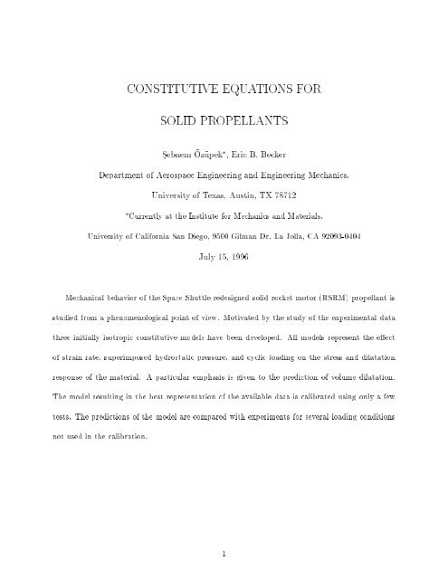
Mechanical behavior of the Space Shuttle redesigned solid rocket motor (RSRM) propellant is<br />
studied from a phenomenological point of view. Motivated by the study of the experimental data<br />
three initially isotropic constitutive models have been developed. All models represent the eect<br />
of strain rate, superimposed hydrostatic pressure, and cyclic loading on the stress and dilatation<br />
response of the material. A particular emphasis is given to the prediction of volume dilatation.<br />
The model resulting in the best representation of the available data is calibrated using only a few<br />
tests. The predictions of the model are compared with experiments for several loading conditions<br />
not used in the calibration.<br />
1
1 Introduction<br />
All modern solid propellants use an elastomeric binder which is lled with a quite high levels<br />
of solid particles 1 .<br />
The application of a load causes dierent mechanisms to take place in the<br />
binder, the ller or the interface between them such as the breakage of polymer chains, breakage<br />
and reformation of weak bonds, deformation and geometrical rearrangement of ller particles,<br />
interfacial debonding, also called dewetting, the formation of microvoids at or near the interface<br />
of the particles and surrounding matrix.<br />
Under these inuences solid propellants exhibit very<br />
complicated behavior including features associated with time and rate eects, temperature and<br />
superimposed pressure dependence, large deformations and large strains, stress softening during<br />
cyclic loading, and transition from incompressible to compressible behavior.<br />
In the following, we describe briey some observations regarding the test data of the particular<br />
propellant we are interested in and review some recent constitutive models. In Section 2 we present<br />
three constitutive models and discuss the limitations and distinctive features associated with them.<br />
In Section 3 we calibrate the model that best represents the data and in Section 4 we compare<br />
the predictions with the experimental data. Finally, in Section 5 we present some observations<br />
regarding our current work and future developments.<br />
Observable Propellant Phenomena<br />
The experimental data for the RSRM propellant has been provided by the Thiokol Corporation<br />
[8], and consist mainly of uniaxial constant strain rate tests with various loading histories and<br />
superimposed pressure levels, and relaxation tests at various temperatures. The tests were conducted<br />
on Instron machines. For relaxation tests dilatation was calculated by measuring geometric<br />
changes of the specimen with a laser micrometer. For constant rate tests a Farris Gas Dilatometer<br />
was used to measure the volume change.<br />
1 RSRM propellant consists of a PBAN polymer binder and 86% by weight of solid particles which are oxidizer<br />
and fuel mainly.<br />
2
It is important to mention the fact that solid propellants are noted for their variability in test<br />
data. Stress-strain-dilatation curves that we reference in this paper, show the results of a single<br />
test which best represents the average behavior of all specimens. Stress and strain measures used<br />
in plotting both the test data and model predictions are the nominal stress and the ratio of change<br />
in length to the reference length, respectively.<br />
Typical uniaxial stress strain curves are shown in Figures 1-2. Major propellant phenomena<br />
that we infer from the test data are the following.<br />
The stress response of the material depends on strain rate, a typical manifestation of viscoelasticity.<br />
Dilatation exhibits little rate dependence for constant strain rate tests and no measurable<br />
time dependence for relaxation tests. The time independence of dilatation suggests that volumetric<br />
behavior is viscoelastic as well as the deviatoric one.<br />
The yielding nature of the stress-strain curve is coincidental with signicant volumetric increase.<br />
As the voids, which form after dewetting, increase in number and size with deformation, the<br />
propellant becomes increasingly compressible. Stress softening and dilatation due to dewetting and<br />
formation of voids, is the dominant nonlinearity observed in loading of propellants and must be<br />
included in any meaningful constitutive theory.<br />
Debonding and formation of voids are postponed or may stop altogether under the inuence of<br />
superimposed hydrostatic pressure. The fact that positive dilatation can occur when all stresses<br />
are compressive, suggests a signicant coupling between dilatational and distortional behavior.<br />
Upon unloading the stress initially decreases rapidly. A large degree of softening is present at<br />
strains less than the previous maximum strain beyond which the reloading curve gradually joins<br />
the monotonic loading curve. The dependence of stress on the past maximum strain results in a<br />
large amount ofhysteresis which cannot be accounted for by viscoelasticity alone. Most of the<br />
dilatation is recovered on unloading. The eects of cyclic loading are present for both small and<br />
large strains, with and without a superimposed pressure environment.<br />
3
The material exhibits large strains and large deformations which increases the complexity of<br />
modelling. Another important phenomenon not shown in the gures is temperature dependence.<br />
Both stress and dilatation responses of propellant are inversely related to temperature. Linear or<br />
nonlinear models based on thermorheologically simple behavior, a common assumption made for<br />
viscoelastic materials, underpredict the response for transient thermal conditions.<br />
Review of Recent Models<br />
The attempt to represent all aspects of propellant behavior would result in a very complex<br />
constitutive model and would require a wide range of tests to characterize the propellant. Thus a<br />
number of previous investigations have been concerned with certain features only.<br />
In his most recent attempt Peng [15] accounts for time and rate dependence through a single<br />
relaxation function and assumes separability of the potential function into dilatation and distortion<br />
parts. He introduces a dewetting criterion which determines the transition from incompressible<br />
to compressible behavior. Although the predictions are quite successful for tests included in the<br />
calibration, the model has a large number of tting parameters and the assumption of separability<br />
is not supported by experimental data.<br />
With a purely micromechanical approach Davis [2, 3] describes the behavior of amorphous<br />
polymeric binder based on its molecular properties, the interaction among the particles which are<br />
assumed to be rigid and spherical, and the inuence of particle packing on polymeric binder. The<br />
resulting model represents the chain extension and orientation, breakage of chains, and state of<br />
dewetting. Although the model is very attractive in that it is free of curve-tting constants, its<br />
applicability depends on its computational tractability aswell as its extension to include large<br />
deformations and arbitrary multiaxiality.<br />
Dunham and Wong's rate formulation [4] treats loading and relaxation separately and successfully<br />
represents loading behavior for complex strain histories. Dilatation is assumed to start at a<br />
certain eective strain level and not to recover on unloading. Propellant data of interest here does<br />
4
not support the latter assumption and data scatter makes the determination of the eective strain<br />
rather dicult. The model does not account for the eect of superimposed pressure.<br />
Farris' [5] constitutive equation is composed of time-independent bulk response and timedependent<br />
deviatoric response.<br />
The memory eects are represented by allowing viscoelasticity<br />
only during unloading. Bulk and deviatoric responses are coupled in that dilatation depends on<br />
distortional strain invariants. Although the theory has been successful in predicting the response<br />
accurately for small deformations and strain histories included in the material characterization,<br />
it has showed poor agreement for those not included in the charaterization, and its extension to<br />
account for large deformations is not straightforward.<br />
Schapery's thermodynamic formulation [19,20] is guided by a micromechanical model [18] which<br />
consists of a rigid spherical particle embedded in an incompressible matrix with two axisymmetric<br />
cracks. Park [13] has extended Schapery's model by including viscoelasticity eects through an<br />
elasticviscoelastic<br />
correspondence principle, and time-dependent changes in the microstructure by employing<br />
two damage parameters with a rate-type, power-law evolution law. The model predicts the<br />
material behavior successfully for constant strain rate and dual strain rate uniaxial extensions at<br />
dierent temperatures and pressures. Further considerations are necessary to extend the model to<br />
include nite deformations, unloading and general multiaxial loading conditions.<br />
Based on Simo's [21] three-dimensional nite strain viscoelastic formulation Ozupek and Becker<br />
[11] have devepoled a phenomenological model which is applicable over any range of deformations<br />
and has an easy calibration. The model has been implemented in the nite element code TEX-<br />
PAC [1]. Although the stress predictions for uniaxial complex loading histories and simultaneous<br />
straining and cooling are in reasonable agreement with the experimental data, the model cannot<br />
accurately predict dilatation response and the eect of superimposed pressure, and it has yet<br />
to be checked for multixial loading. Some other models developed for propellants or particulate<br />
5
composites are reviewed in [10, 12] and will not be repeated here.<br />
2 Constitutive Models<br />
Our major goal is to obtain an isotropic three-dimensional model which can be calibrated with only<br />
a few tests and incorporated in a nite element code without any major diculty. Motivated by<br />
the study of the RSRM test data we intend to represent the eects of strain rate, superimposed<br />
pressure and cyclic loading on the stress and dilatation response of the propellant. In the following,<br />
we rst develop a constitutive model in terms of generalized variables [16] and then obtain three<br />
formulations by dierent selection of these variables.<br />
Viscoelasticity<br />
We incorporate the viscoelastic eect by employing an integral representation and relate the<br />
actual force Q to the pseudo-force Q r in the form<br />
Q = 1 E r<br />
Z<br />
t<br />
0<br />
E(t , ) @Qr<br />
d (1)<br />
@<br />
such that the entire rate-dependent portion of the response is characterized by the relaxation function<br />
E(t). In order to account for the time-independent dilatation response we let both deviatoric<br />
and volumetric response obey the superposition principle through the same relaxation function.<br />
The coecient E r in equation (1) is an arbitrarily selected reference modulus which isintroduced<br />
so that Q and Q r have the same units.<br />
We assume that the pseudo-generalized force Q r is related to generalized displacement q through<br />
an elastic stress-strain law in the form<br />
Q r = @d (q;s i )<br />
@q<br />
(2)<br />
The function d denotes the pseudo-free energy of damaging material and is a function of the<br />
6
current generalized displacement q and the internal state variables s i which are employed in order<br />
to incorporate some nonlinearities of the propellant behavior.<br />
Dilatation<br />
In developing the dilatation model we are motivated by the behavior of an externally pressurized<br />
thick-walled spherical shell. Based on its agreement with our test data we consider the pressurevolume<br />
relation [22]<br />
<br />
V V<br />
<br />
= + exp ,3p=4 (3)<br />
V 0 V 0 m<br />
where the total volume change, V=V 0 , consists of two parts. (V=V 0 ) m is the volume change of<br />
the shell material, while the second term gives the volume contribution of the initial void content<br />
, modied by an exponential multiplier containing terms due to pressure p, shear modulus of<br />
the shell material, and a constant shape factor, as a negative exponent.<br />
We assume that the following modied form of equation (3) can represent the volumetric response<br />
of propellant under general loading conditions:<br />
V<br />
V 0<br />
= T r m<br />
K(c) + c (4)<br />
The rst term of equation (3) is usually considered as proportional to the mean stress Tm r with<br />
the proportionality constant representing the bulk modulus K of the shell material. In our case the<br />
shell material is the propellant with some eective properties that depend primarily on damage. To<br />
account for this we let the bulk modulus be a function of c, the volume fraction of voids, through<br />
an expression that results from the dierential scheme [7]<br />
dK<br />
dc = , K<br />
1 , c (1 + CK) with K = K 0 at c =0 (5)<br />
where C is a curve-tting parameter and represents the eect of particle shape and the shear<br />
7
modulus.<br />
The second term in equation (4) represents the formation and growth of voids for loading.<br />
The value of c decreases during unloading and may vanish as voids collapse into cracks.<br />
For<br />
computational purposes we consider the calculation of c from an evolution equation in the form<br />
_c = _ exp T r m =B with = AI n (6)<br />
where I is a strain measure which is incorporated to represent the eect of distortion on formation<br />
and growth of voids. It can be expressed in terms of volume-preserving invariants as<br />
I = 1 6 (2I2 1 , 6I 2 ) 1=2 (7)<br />
and it reduces to the octahedral shear strain for innitesimal deformations. The exponential term<br />
in equation (6) represents mainly the eect of the superimposed pressure, and B and n are curve-<br />
tting parameters.<br />
For an elastic material and a xed void volume fraction, i. e. for constant E(t) and c, respectively,<br />
the dilatation model developed above reduces to equation (3).<br />
Construction of a Free Energy Function<br />
We now postulate a form for the free energy function d of the damaging material and identify<br />
internal state variables such that we will be able to obtain the volumetric response we discussed<br />
above and represent other propellant phenomena we described previously.<br />
For computational purposes we express the dependence of d on the deformation through the<br />
volume-preserving invariants I 1 ; I 2 and the volume change ratio J in the form<br />
d = d (I i ;s i )+ ^ d (J;s i ) (8)<br />
8
where we introduce coupling of deviatoric and volumetric responses through the internal state<br />
variables s i .<br />
The expression of ^ d that results in the dilatation model given in equation (4) is<br />
^ d = K(c)<br />
2 (J , 1)2 , K(c)c(J , 1) (9)<br />
where c is an internal state variable, i. e. it is treated as a constant while dierentiating ^ d with<br />
respect to J.<br />
In selecting a form for the deviatoric part of the free energy function, we postulate that the<br />
dependence of d on I k and s i can be separated as<br />
d (I 1 ; I 2 ;s i )=d(s i )(I 1 ; I 2 ) (10)<br />
where is the free energy of the undamaged material and is modied by the function d to account<br />
for damage and some of the other observable propellant phenomena, such as cyclic eects.<br />
The simplest form of that represents the undamaged stress-strain curve is a single term Rivlin<br />
polynomial. In order to get a better t at small strains we use an additional exponential term [23]<br />
so that the function becomes<br />
(I 1 ; I 2 )= 1<br />
2<br />
f1 + exp[, 2 (I 1 , 3)]g + 1 (I 1 , 3) (11)<br />
where 1 ; 2 and 1 are to be determined from curve tting the data.<br />
During monotonic loading the function d in equation (10) represents the softening of the material<br />
due the formation and growth of voids. Therefore, we let d to depend on c max , the maximum volume<br />
fraction of voids up to the present time.<br />
9
Cyclic Eect<br />
In order to represent cyclic eects, i. e. the rapid decrease of stress during unloading, the large<br />
amount ofhysteresis in load/unload cycles, and the dependence of response on the maximum strain<br />
previously attained, we introduce another internal state variable as an argument ofd and postulate<br />
the form<br />
d(s i )=g(s 1 )f(s 2 ) (12)<br />
where g is the damage function with argument s 1 = c max as introduced above. The function f<br />
represents the eect of cyclic loading and is allowed to dier for the situations of unloading and<br />
reloading.<br />
A reasonable choice for the argument of function f representing the joining of the reloading<br />
curve to the original loading curve beyond the previous maximum strain is<br />
s 2 =<br />
I <br />
I max<br />
(13)<br />
where I max<br />
represents the maximum I previously achieved during the loading history. During<br />
loading s 2 is unity. Its value decreases during unloading, and increases during reloading. For<br />
the latter we allow s 2 > 1, since we consider a given state as reloading until it rejoins the original<br />
loading curve. In this manner we account for the fact that reloading curve joins the original loading<br />
curve gradually.<br />
In order to implement the eect of cyclic loading into the model we apply the following criterion<br />
to distinguish between rst loading, on the one hand, and unloading/reloading, on the other<br />
_c(t) < 0 unloading ) _ f = _ f u<br />
_c(t) 0 and f(t) < 1 reloading ) _ f = _ f r<br />
_c(t) 0 and f(t) =1 loading ) _ f =0 (14)<br />
10
where _c is the rate of change of the volume fraction of voids. We note that f represents mechanisms<br />
which may cause both further softening and hardening of the material during unloading and<br />
reloading, such as the breakage and reformation of weak bonds.<br />
Selection of Generalized Variables<br />
We now present three formulations obtained from the constitutive equations 1 and 2 by dierent<br />
selection of generalized variables. The procedure involves the following steps:<br />
choose generalized displacements q,<br />
dene the corresponding generalized forces Q using the virtual work condition W = Qq,<br />
derive the generalized pseudo-forces Q r according to (2) from the energy function given in (8),<br />
relate the generalized forces Q to their pseudo counterparts Q r<br />
through the convolution<br />
integral (1),<br />
apply the model to axial extension under superimposed pressure.<br />
MODEL I<br />
If q is selected as the deformation gradient F, then Q becomes the nominal stress tensor ,<br />
and equations (1) and (2) can be expressed as<br />
r = @d<br />
@F<br />
= 1 E r<br />
Z<br />
t<br />
0<br />
E(t , ) @r<br />
d (15)<br />
@<br />
MODEL II<br />
If q is selected as the Green's strain E, then Q becomes the symmetric Piola-Kirchho stress<br />
tensor S, and constitutive equations can be expressed as<br />
S r = @d<br />
@E<br />
11
S = 1 E r<br />
Z<br />
t<br />
0<br />
E(t , ) @Sr<br />
d (16)<br />
@<br />
MODEL III<br />
If q is selected as the two principal stretches 1 ; 2 , and the volume ratio J, then Q becomes<br />
Q i = i , 3<br />
3<br />
i<br />
(i =1; 2)<br />
Q 3 = 3<br />
3<br />
J<br />
(17)<br />
and constitutive equations can be expressed as<br />
Q r i = @d (i =1; 2); Q r 3 = @d<br />
@ i @J<br />
(18)<br />
and<br />
i , 3<br />
3<br />
i<br />
= 1 E r<br />
Z<br />
3<br />
3<br />
J<br />
= 1 E r<br />
Z<br />
t<br />
0<br />
t<br />
0<br />
E(t , ) @Qr i<br />
@<br />
d (i =1; 2)<br />
E(t , ) @Qr 3<br />
d (19)<br />
@<br />
Comparison of Models<br />
The elastic portions of each model, i. e. pseudo stress-strain relations, are basically equivalent.<br />
The dierences result from applying the convolution integral to dierent pseudo-stress measures.<br />
The following are the distinguishing features of each model and must be considered when a model<br />
is applied to a particular propellant. Further detail regarding these features can be found in [12].<br />
Model I is suitable for the application of the correspondence principle as introduced in [17].<br />
By enabling the construction of solutions to a viscoelastic boundary value problem from solutions<br />
of the corresponding elastic boundary value problem, this principle results in signicant<br />
computational simplications.<br />
12
Model II is applicable over any range of deformations since it satises the objectivity principle.<br />
For other models material objectivity may not be satised when large deformations exist; i.<br />
e. generally material response will be aected by rigid-body rotations.<br />
Model III results in the best representation of the pressure eect before the onset of dilatation,<br />
as seen in Figure 4. We note that RSRM test data show dierent behavior regarding the<br />
dependence on superimposed pressure, i. e. at a high strain rate we observe dierent initial<br />
slopes at dierent pressure levels, while we have basically the same slope at a lower strain<br />
rate. Since the latter has been found to be typical of propellant behavior in previous works,<br />
we assumed the pressure dependence to be a data scatter. If further test results support the<br />
dependence on pressure, then RSRM data would be better represented through models I and<br />
II.<br />
Finally, we note that for innitesimal deformations and for an undamaged material, i. e. for<br />
d = 1 and c = 0, all models reduce to stress-strain relation for an isotropic linear viscoelastic<br />
material.<br />
3 Calibration<br />
We now consider the calibration of model III since in previous section we concluded that this model<br />
would result in the best representation of the available experimental data for RSRM propellant.<br />
The calibration procedure consists of determining the various material functions and constants as<br />
described below. The values of the material parameters are given in Table 1.<br />
Tensile relaxation modulus:<br />
We obtain E(t) using the relaxation tests at dierent temperatures. In order to account for<br />
the thermorheologically complex behavior we incorporate a vertical shift of relaxation curves. We<br />
then shift the resulting curves horizontally and determine the shift factor at each temperature. We<br />
13
approximate the resulting master curve by a Prony series given in Table 1 and choose E r equal to<br />
the instanteneous relaxation modulus.<br />
Coecients of the Energy Function of the Undamaged Material:<br />
We calculate the coecients of by tting the model to a constant strain rate test data in the<br />
least-squares sense. In particular, we use unpressurized 0.714 min ,1 test up to the beginning of<br />
damage, i. e. onset of dilatation.<br />
Dilatation Model Parameters:<br />
Parameters in the evolution equation for void volume fraction, c, and bulk modulus, K, are<br />
determined from the same constant strain rate test data used in calculating coecients of , i.e.<br />
the unpressurized test at 0.714 min ,1 . Both stress-strain and dilatation-strain data up to failure<br />
are used. Among several combinations of A; B; n and C, the one representing dilatation response<br />
for pressurized test at 0.714 min ,1 the best is selected as the suitable set of parameters and is given<br />
in Table 1.<br />
Damage Function for Loading:<br />
The softening function g is determined from the unpressurized constant strain rate test at 0.714<br />
min ,1 , as the ratio of the measured to calculated stresses. The resulting curve isshown in Figure<br />
3.<br />
Unloading/Reloading Function:<br />
The material functions f u and f r are calculated from the unpressurized cyclic test at 0.714<br />
min ,1 and 20% unloading strain level and are shown in Figure 3. In order to prevent a jump in<br />
the calculated response upon reversing the loading direction, therefore shifting from one curve to<br />
the other, we introduce a new variable I rel dened as<br />
I rel =<br />
I , I min<br />
I max , I min<br />
(20)<br />
14
E i ; MPa i ; min Coecients of <br />
41:2090 0:4754E , 5 1 = 17.37 MPa<br />
23:8352 0:4754E , 4 2 = 17.60<br />
13:1239 0:4754E , 3 1 = 26.70 MPa<br />
6:6967 0:4754E , 2<br />
3:3614 0:4754E , 1 Dilatation Parameters<br />
0:9848 0:4754E +0 A = 1.5<br />
0:6038 0:4754E +1 B = 0:667( E R<br />
3<br />
)<br />
0:5967 0:4754E +2 n = 2<br />
0:7204 0:4754E +3 C = 0:167( E R<br />
3<br />
) ,1<br />
1:2261 0:4754E +4 K 0 = 10 5 MPa<br />
E eq = 0:9227<br />
Table 1: Tensile relaxation modulus and other material constants.<br />
where I min is the value at the end of unloading. The value of f is then determined according to<br />
I <br />
!<br />
f = f u if unloading from a loading curve<br />
I max<br />
I <br />
!<br />
f = f u f r=u (I rel ) if unloading from a reloading curve<br />
I max<br />
or if reloading (21)<br />
where f r=u (I rel ) denotes the ratio of reloading and unloading functions. We note that loading,<br />
unloading and reloading functions are determined using a table, rather than assuming any analytic<br />
form.<br />
4 Predictions<br />
Predictions of the constitutive model calibrated in previous section are shown in Figures 4-11. The<br />
following observations can be made regarding the performance of the model:<br />
The eect of superimposed pressure is represented quite well for dilatational response and<br />
reasonably well for stress response as seen in Figure 4.<br />
Recall that only the data at ambient<br />
pressure have been used in calibration.<br />
15
The rate eect on stress response is reasonably represented for low-moderate strain rates, while<br />
it is overpredicted for high rate. The overprediction of the response at high pressure levels is not<br />
as pronounced as it is at ambient pressure as shown in Figure 5.<br />
Stress and dilatation predictions are successful for both single and multiple cyclic loading as<br />
seen in Figures 6-9.<br />
The discrepancy observed near the end of unloading states is due to the<br />
modication of the unloading/reloading function f as has been described during the calibration<br />
procedure.<br />
For the equibiaxial tension tests at constant strain rate maximum stresses predicted by the<br />
model are quite close to the experimental values for low strain rates, however, they are overpredicted<br />
for high rates as seen in Figure 10. For equibiaxial cyclic loading the agreement of the model with<br />
the experiment is quite satisfactory as shown in Figure 11. We note that biaxial test data were<br />
provided by a dierent source [14]. Therefore, part of the discrepancy between the predictions and<br />
constant rate data may be due to the use of dierent experimental methods.<br />
5 Conclusions<br />
Three isotropic constitutive models representing the mechanical behavior of the RSRM propellant<br />
have been developed. The models employ a pseudo-energy function from which pseudo-stress-strain<br />
equations are derived. The actual stresses are related to pseudo-stresses through a convolution integral.<br />
A signicant coupling between volumetric and deviatoric response has been introduced.<br />
Softening of the material due to damage and nonlinearities during cyclic loading have been represented.<br />
A procedure has been developed for the calibration of the models which requires relaxation<br />
tests at various temperatures to determine the master curve, and a constant strain rate test with<br />
monotonic and cyclic loading, both at ambient pressure, to determine all other model constants and<br />
functions. The calibration has been carried out for the model resulting in the best representation<br />
of the available data, and the predictions have been compared with experiments for several loading<br />
16
conditions not used in the calibration.<br />
An important aspect regarding the application of constitutive models presented in this paper<br />
is their implementation into a nite element code. Most of the work regarding this issue has been<br />
completed and the results will soon be published.<br />
Another important area of work appears to be the experimental one. The observation regarding<br />
pressure independent behavior of stress before the onset of dilatation does not seem to hold at high<br />
strain rates. Further testing is necessary in order to determine this and some other propellant<br />
phenomena such as thermal eects more accurately.<br />
Although the features of the constitutive models were motivated by the study of the RSRM test<br />
data, they represent typical propellant phenomena. Therefore, the models can be used in predicting<br />
the response of other propellants after the calibration for a specic propellant is performed. The<br />
selection of one of the constitutive relations depends on which of the features distinguishing the<br />
models from each other is emphasized in a particular application.<br />
Acknowledgement<br />
We would like to express our appreciation to Dr. Dave Flanigan of Thiokol Inc. for supporting<br />
major part of this research and Mr. John Nelson who obtained most of the test data.<br />
References<br />
[1] Becker, E. B. and Miller T., \User's Manual for the TEXPAC Computer Code," Mechanics Software Inc. ,<br />
Austin, Texas, 1989.<br />
[2] Davis, I. L., \Microstructural Propellant Constitutive Theory: Polymeric Binder Mechanical Properties Based<br />
on Molecular Structure," 1994 JANNAF Structures and Mechanical Behavior Subcommittee Meeting, Hill AFB,<br />
Utah, October 1994.<br />
[3] Davis, I. L., \Microstructural Propellant Constitutive Theory: Inuence of Particle Pack on Propellant Mechanical<br />
Properties," 1994 JANNAF Structures and Mechanical Behavior Subcommittee Meeting, Hill AFB, Utah,<br />
October 1994.<br />
17
[4] Dunham, R. and Wong F., \Progress on the Relax/Reload Nonlinear Viscoelastic Constitutive Model," ANAT-<br />
ECH Research Corp. , San Diego, California, 1992.<br />
[5] Farris, R. J., and Schapery, R. A., \Development of a Solid Propellant Constitutive Theory," AFRPL-TR-73-50,<br />
June 1973.<br />
[6] Huerd, W. L., Briggs, W. E. and Francis, E. C., \Nonlinear Constitutive Theory Transition," Interim Report,<br />
AFAL TR-88-030, July 1988.<br />
[7] McLaughlin, R., \A Study of the Dierential Scheme for Composite Materials," Int J Engng Sci, Vol 15, pp.<br />
237-244, 1977.<br />
[8] Nelson, J., \Linear Viscoelastic Characterization of Redesigned Solid Rocket Motor Propellant" Interim Report,<br />
Thiokol Corporation TR-88-030, July 1993.<br />
[9] Ogden, R. W., Non-Linear Elastic Deformations, Ellis Horwood, Chichester, U. K., 1984.<br />
[10] Ozupek, S., \Constitutive Modeling of High Elongation Solid Propellants," Thesis, pp. xi+85, the University of<br />
Texas, Austin, August 1989.<br />
[11] Ozupek, S. and Becker, E. B., \Constitutive Modeling of High-Elongation Solid Propellants,"J Engrng Matls<br />
Tech, Vol 114, pp. 111-115, 1992.<br />
[12] Ozupek, S., \Constitutive Equations for Solid Propellants," Dissertation, pp. xiii+120, The University ofTexas,<br />
Austin, August 1995.<br />
[13] Park, S., \Development of a Nonlinear Viscoelastic Constitutive Equation for Particulate Composites with<br />
Growing Damage,' Dissertation, The University ofTexas at Austin, December 1994.<br />
[14] Peng, S. T. J., \Analysis of Nonlinear Response of Shuttle Propellant - Quarterly Report December 1991-<br />
February 1992," Jet Propulsion Laboratory, Pasadena, California, March 1992.<br />
[15] Peng, S. T. J., \Constitutive Equations of Solid Propellant With Volume Dilatation Under Multiaxial Loading<br />
- Theory of Dilatation and Dewetting Criterion," 1992 JANNAF Propulsion Meeting, Indianapolis, Indiana,<br />
February 1992.<br />
[16] Schapery, R. A., \A Theory of Nonlinear Thermoviscoelasticity based on Irreversible Thermodynamics," Proceedings<br />
Fourth U. S. National Congress of Applied Mechanics, The American Society of Mechanical Engineers,<br />
pp. 511-530, 1966.<br />
[17] Schapery, R. A., \Correspondence Principles and a Generalized J-Integral for Large Deformation and Fracture<br />
Analysis of Viscoelastic Media," IntJFracture, Vol 25, pp. 195-223, 1984.<br />
18
[18] Schapery, R. A., \A Micromechanical Model for Nonlinear Viscoelastic Behavior of Particle{Reinforced Rubber<br />
with Distributed Damage," Engrng Fracture Mechanics, Vol 25, pp. 845-867, 1986.<br />
[19] Schapery, R. A., \Simplications in the Behavior of Viscoelastic Composites with Growing Damage," Proceedings<br />
of the IUTAM Symposium on Inelastic Deformation of Composite Materials, May 29-June 1, 1990.<br />
[20] Schapery, R. A., \Analysis of Damage Growth in Particulate Composites Using a Work Potential," Compos<br />
Engng, Vol 1, pp. 167-182, 1991.<br />
[21] Simo, J. C., \On a Fully Three{Dimensional Finite{Strain Viscoelastic Damage Model: Formulation and Computational<br />
Aspects,"Computer Methds in Appl Mech and Engrng, Vol 60, pp. 153-173, 1987.<br />
[22] Surland, C. C., \Compressibility of Elastomers with Crystalline Fillers and Microvoid Inhomogeneities Related<br />
to Various Empirical Equations of State for Liquids and Solids," J App Poly Sci, Vol 11, pp. 1227-1249, 1967.<br />
[23] Yeoh, O. H., \Some Forms of the Strain Energy Function for Rubber," Rubber Chem and Technol, Vol 66, pp.<br />
754-771, 1993.<br />
19
Nomenclature<br />
A; B; n constitutive constants in evolution equation of c<br />
C<br />
c<br />
E<br />
E(t)<br />
E r<br />
F<br />
f<br />
g<br />
I i<br />
I <br />
J<br />
K<br />
K 0 ;C<br />
p<br />
q<br />
Q<br />
Q r<br />
S<br />
s i<br />
T<br />
t<br />
1 ; 2 ; 1<br />
i<br />
right Cauchy-Green deformation tensor<br />
void volume fraction<br />
Green strain tensor<br />
tensile relaxation modulus<br />
reference modulus<br />
deformation gradient<br />
unloading/reloading function<br />
softening function<br />
invariants of the volume-preserving part of C<br />
\octahedral shear" strain<br />
ratio of current to reference volume<br />
bulk modulus<br />
constitutive constants in evolution equation of K<br />
superimposed pressure<br />
generalized displacement<br />
generalized force<br />
pseudo-generalized force<br />
symmetric Piola-Kirchho stress tensor<br />
internal state variables<br />
Cauchy stress tensor<br />
current time<br />
constitutive constants in <br />
principal stretches<br />
20
d<br />
<br />
shear modulus<br />
nominal stress tensor<br />
free energy function of damaged material<br />
a time variable<br />
21
Figure 1: Eect of strain rate at 0 MPa (above), and eect of superimposed pressure at 0.714<br />
min ,1 , in uniaxial tensile constant strain rate tests at 25 o C.<br />
Figure 2: Uniaxial cyclic tensile test at 0 MPa, 25 o C and 0.714 min ,1 .<br />
Figure 3: Loading damage function g (above) and unloading/reloading functions f u , f r .<br />
Figure 4: Uniaxial constant strain rate tests at 25 o C and 0.714 min ,1 .<br />
Figure 5: Uniaxial constant strain rate tests at 25 o C.<br />
Figure 6: Uniaxial cyclic tensile test at 0 MPa, 25 o C and 0.714 min ,1 , with 1 cycle at 10% strain.<br />
Figure 7: Uniaxial cyclic tensile test at 500 MPa superimposed pressure, 25 o C and 0.714 min ,1 ,<br />
with 1 cycle at 20% strain.<br />
Figure 8: Uniaxial cyclic tensile test at 0 MPa, 25 o C and 0.714 min ,1 , with cycles at 10%, 15%,<br />
20%, 25% strain.<br />
Figure 9: Uniaxial cyclic tensile test at 0 MPa, 25 o C and 0.714 min ,1 , with 10 cycles at 20% strain.<br />
Figure 10: Equibiaxial constant strain rate tests at 0 MPa and 25 o C.<br />
Figure 11: Equibiaxial cyclic tensile test at 0 MPa, 25 o C and 0.069 min ,1 , with unloading at 10%<br />
strain.<br />
22
1.2<br />
0.15<br />
Stress (MPa)<br />
0.9<br />
0.6<br />
0.3<br />
rate (1/min)<br />
7.14<br />
0.357<br />
0.0714<br />
0.10<br />
0.05<br />
Dilatation<br />
0.00714<br />
0<br />
0.00<br />
0 0.1 0.2 0.3 0.4 0.5<br />
Strain<br />
0.15<br />
2<br />
Stress (MPa)<br />
1.5<br />
1<br />
0.5<br />
pressure (MPa)<br />
0<br />
0.7<br />
1.7<br />
3.4<br />
5.5<br />
0.10<br />
0.05<br />
Dilatation<br />
0<br />
6.9<br />
0.00<br />
0 0.1 0.2 0.3 0.4 0.5<br />
Strain<br />
Figure 1<br />
(Sebnem Ozupek)<br />
23
1<br />
0.8<br />
Stress (MPa)<br />
0.6<br />
0.4<br />
0.2<br />
0<br />
10%<br />
20%<br />
monotonic<br />
0 0.1 0.2 0.3 0.4<br />
Strain<br />
0.12<br />
0.09<br />
Dilatation<br />
0.06<br />
0.03<br />
10%<br />
20%<br />
monotonic<br />
0.00<br />
0 0.1 0.2 0.3 0.4<br />
Strain<br />
Figure 2<br />
(Sebnem Ozupek)<br />
24
1<br />
0.8<br />
0.6<br />
0.4<br />
0.2<br />
0<br />
1.2<br />
0.8<br />
f<br />
g<br />
0 0.02 0.04 0.06 0.08 0.1 0.12 0.14<br />
c<br />
0.4<br />
f_u<br />
f_r<br />
0.0<br />
0.0 0.4 0.8 1.2 1.6<br />
I /I max<br />
Figure 3<br />
(Sebnem Ozupek)<br />
25
Stress (MPa)<br />
2.5<br />
2<br />
1.5<br />
1<br />
measured<br />
predicted<br />
1.7<br />
0.7<br />
0 MPa<br />
6.9<br />
3.4<br />
0.5<br />
0<br />
0 0.1 0.2 0.3 0.4<br />
Strain<br />
0.1<br />
measured<br />
predicted<br />
0 MPa<br />
Dilatation<br />
0.06<br />
0.02<br />
0.7<br />
1.7<br />
3.4<br />
-0.02<br />
0 0.1 0.2 0.3 0.4<br />
Strain<br />
6.9<br />
Figure 4<br />
(Sebnem Ozupek)<br />
26
3.5<br />
3<br />
measured<br />
predicted<br />
7.14/6.9<br />
Stress (MPa)<br />
2.5<br />
2<br />
1.5<br />
1<br />
0.5<br />
0.357/0<br />
-1<br />
0.0714min / 0MPa<br />
7.14/3.4<br />
7.14/0<br />
0<br />
0 0.1 0.2 0.3 0.4<br />
Strain<br />
0.16<br />
0.14<br />
0.12<br />
measured<br />
predicted<br />
-1<br />
7.14min / 0MPa<br />
Dilatation<br />
0.1<br />
0.08<br />
0.06<br />
0.04<br />
0.357/0<br />
0.02<br />
0<br />
0.0714/0<br />
7.14/3.4<br />
7.14/6.9<br />
-0.02<br />
0 0.1 0.2 0.3 0.4<br />
Strain<br />
Figure 5<br />
(Sebnem Ozupek)<br />
27
1<br />
0.8<br />
Stress (MPa)<br />
0.6<br />
0.4<br />
0.2<br />
measured<br />
predicted<br />
0<br />
0 0.1 0.2 0.3 0.4<br />
Strain<br />
0.12<br />
0.09<br />
Dilatation<br />
0.06<br />
0.03<br />
measured<br />
predicted<br />
0<br />
0 0.1 0.2 0.3 0.4<br />
Strain<br />
Figure 6<br />
(Sebnem Ozupek)<br />
28
2.5<br />
2<br />
Stress (MPa)<br />
1.5<br />
1<br />
0.5<br />
measured<br />
predicted<br />
0<br />
0 0.1 0.2 0.3 0.4 0.5<br />
Strain<br />
Figure 7<br />
(Sebnem Ozupek)<br />
29
1.1<br />
measured<br />
predicted<br />
Stress (MPa)<br />
0.8<br />
0.5<br />
0.2<br />
-0.1<br />
0 0.5 1 1.5 2 2.5<br />
Time (min)<br />
0.1<br />
measured<br />
predicted<br />
0.07<br />
Dilatation<br />
0.04<br />
0.01<br />
-0.02<br />
0 0.5 1 1.5 2 2.5<br />
Time (min)<br />
Figure 8<br />
(Sebnem Ozupek)<br />
30
1.1<br />
measured<br />
predicted<br />
0.8<br />
Stress (MPa)<br />
0.5<br />
0.2<br />
-0.1<br />
0 1 2 3 4 5 6<br />
Time (min)<br />
0.13<br />
0.1<br />
measured<br />
predicted<br />
Dilatation<br />
0.07<br />
0.04<br />
0.01<br />
-0.02<br />
0 1 2 3 4 5 6<br />
Time (min)<br />
Figure 9<br />
(Sebnem Ozupek)<br />
31
1<br />
Stress (MPa)<br />
0.8<br />
0.6<br />
0.4<br />
predicted<br />
0.2<br />
0.0028 /min<br />
0.3588 /min<br />
0.0345 /min 0.6882 /min<br />
0<br />
0 0.05 0.1 0.15 0.2 0.25<br />
Strain<br />
Figure 10<br />
(Sebnem Ozupek)<br />
32
0.8<br />
measured<br />
predicted<br />
0.6<br />
Stress (MPa)<br />
0.4<br />
0.2<br />
0<br />
0 1 2 3 4 5 6 7 8 9<br />
Time (min)<br />
Figure 11<br />
(Sebnem Ozupek)<br />
33