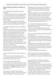
POWER FLUSHING SURVEY and CHECK LIST - Kamco
POWER FLUSHING SURVEY and CHECK LIST - Kamco
POWER FLUSHING SURVEY and CHECK LIST - Kamco

Create successful ePaper yourself
Turn your PDF publications into a flip-book with our unique Google optimized e-Paper software.
© <strong>Kamco</strong>
The <strong>Kamco</strong> ‘CLEARFLOW CF30 CLASSIC’ pump is a purpose built unit for ‘Power Flushing’ central heating<br />
systems, designed to cure circulation <strong>and</strong> boiler noise problems caused by the accumulation of sludge,<br />
corrosion deposits <strong>and</strong> scale.<br />
This manual contains detailed guidelines for the safe use of the pump. How to connect the pump into the<br />
heating system, step by step guide to the flushing process, <strong>and</strong> which chemicals are best suited for each<br />
application.<br />
Please take time to carefully read through these guidelines before using your <strong>Kamco</strong> pump.<br />
Issue: September 2008<br />
©<br />
<strong>Kamco</strong> Ltd<br />
Unit 9 Curo Park, Frogmore, Park Street,<br />
St. Albans, Hertfordshire, AL2 2DD<br />
Tel: 01727 875020<br />
Fax: 01727 875335<br />
Additional information may be obtained from our website:<br />
www.kamco.co.uk<br />
<strong>Kamco</strong>
SECTION A – INTRODUCTION<br />
TECHNICAL DATA<br />
Pump Type: Positive drive centrifugal.<br />
Motor: 0.45 HP, 220v (#) or 110v.<br />
Degree of protection: IP54.<br />
Motor rating: Continuous.<br />
Temperature range: 0°C to 70°C.<br />
Dimensions: Height 63cm, Diameter 41cm.<br />
Weight: 14kg.<br />
# The CLEARFLOW CF30 220v may be used on a domestic 13 ampere supply. A 5amp fuse should<br />
be fitted in the plug top. A residual current circuit breaker adaptor should be used<br />
SAFETY PRECAUTIONS<br />
Precautions should be taken to ensure a safe working environment.<br />
Take care when lifting large or heavy items.<br />
Regularly check power leads for wear or damage, use with a residual circuit breaker.<br />
When h<strong>and</strong>ling chemicals wear suitable protective clothing, gloves <strong>and</strong> goggles.<br />
Use in a well ventilated area.<br />
PAT test (Portable Appliance Test) the electrics annually.<br />
CONTENTS OF THE CLEARFLOW CF30 CLASSIC KIT<br />
Each kit comprises the following:<br />
CLEARFLOW CF30 Classic power flushing pump.<br />
Set of 2 x 3mtr flow <strong>and</strong> return hoses.<br />
1 x 8mtr dump hose.<br />
1 x 3mtr overflow hose.<br />
1 x 5mtr water inlet hose.<br />
2 x 2mtr circulation pump adaptor hoses.<br />
10 part BSP adaptor set.<br />
Waterproof transit container.<br />
Comprehensive operating guidelines.<br />
Starter pack of flushing chemicals.<br />
50 promotional leaflets for advertising.<br />
© <strong>Kamco</strong><br />
Issue: September 2008 Section A – Introduction Page A.1
SECTION B – USING THE CF30 FOR <strong>POWER</strong> <strong>FLUSHING</strong><br />
INTRODUCTION<br />
The CLEARFLOW CF30 pump is designed to power<br />
flush heating systems with minimal dismantling, by<br />
circulating water <strong>and</strong> flushing chemicals at high<br />
velocity, <strong>and</strong> then purging the dirty water from the<br />
system with a high flow of fresh, clean, water.<br />
Radiators may be individually flushed without<br />
removing or disconnecting them from the system.<br />
Your Clearflow pump may be used with any<br />
commercially available flushing <strong>and</strong> descaling<br />
chemical, including strong acids or alkalis.<br />
SYSTEM INSPECTION AND PREPARATION<br />
1. Turn on heating system in order to identify<br />
problem flow areas, cold radiators, or those with<br />
cold spots, etc. Switch off system.<br />
2. Note how many turns are required to shut off<br />
radiator <strong>and</strong> lock shield valves so that settings<br />
may be re-instated after flushing to avoid system<br />
balancing. Use a copy of the chart provided to<br />
record the number of turns.<br />
Open all (both sides of radiator) valves fully.<br />
3. Set any thermostatic radiator valves to the fully<br />
open position. Remove the heads <strong>and</strong> check that<br />
the plunger pin moves freely. Check that diverter<br />
or zone valves are in the fully open position,<br />
setting manually if necessary.<br />
4. If an anti-gravity / check valve is present, this must<br />
be by-passed or bridged to allow the flow<br />
reversing action to be used. It may be possible to<br />
dissemble the anti-gravity valve, <strong>and</strong> remove<br />
internal components.<br />
5. Tie up the ball cock or turn off the mains water<br />
supply by another means.<br />
6 .Drain enough water from the system to empty the<br />
F&E tank. This can be drained into the CF30 if it<br />
has been connected (connection details are in<br />
the next section).<br />
7. With vented systems, it is necessary to cap off, or<br />
loop together, the expansion <strong>and</strong> cold feed pipes<br />
in order to avoid the powerful CF30 filling <strong>and</strong><br />
overflowing the expansion tank.<br />
The F&E pipes may be capped with push fit end<br />
caps, such as Speedfit, Prestek, or Hep2O, or a<br />
temporary compression fitting gate valve.<br />
Pumps with 220 volt motors are single phase, for use<br />
on a st<strong>and</strong>ard domestic supply. A five amp fuse<br />
should be fitted in the plug top. We recommend the<br />
use of a residual current circuit breaker plug or<br />
adapter for extra protection.<br />
Looping the feed <strong>and</strong> expansion pipes together<br />
will enable these pipes to be flushed during the<br />
cleansing process, which can be beneficial when<br />
the cold feed pipe contains corrosion deposits.<br />
NOTE 1: This will only be effective when the F&E<br />
pipes are not close coupled, or connected via an<br />
air separator, <strong>and</strong> may not remove deposits<br />
which have hardened over a long period of time.<br />
NOTE 2: The looping connection may be made with<br />
any sturdy flexible tubing, such as CF30 hose, or<br />
Hep2O, but should incorporate a valve in the loop<br />
to close the circuit when flushing individual<br />
radiators.<br />
Capping or looping the F&E pipes are only<br />
temporary measures, which must be removed<br />
after the flushing process.<br />
ENGINEER’S TIP: Don’t drain water from the system<br />
to lower the water level in the F&E tank until after<br />
the Clearflow pump has been connected into the<br />
system.<br />
Tie up the f & e tank ballcock or otherwise turn off<br />
the cold water feed, <strong>and</strong> return to the Clearflow<br />
pump. Open both the isolating valves, without<br />
switching on the electric motor. The head of<br />
water in the house means that heating system<br />
water will run down the flow <strong>and</strong> return hoses <strong>and</strong><br />
into the Clearflow tank. Let the water run until the<br />
tank is half full, <strong>and</strong> close both isolating valves.<br />
You should now have emptied the f & e tank<br />
sufficiently to carry out the necessary valving or<br />
capping off of the cold feed.<br />
NOTE: If there is a large amount of sludge or<br />
slime present in the f & e tank it must be cleaned<br />
manually <strong>and</strong> not drained into the system.<br />
© <strong>Kamco</strong><br />
Issue: Sept 2008 Section B – Using the CF30 for Power Flushing Page B.1
LOCATION AND CONNECTION OF THE CLEARFLOW PUMP<br />
Alternative connection locations,<br />
1, 2, <strong>and</strong> 3,<br />
for a CLEARFLOW<br />
power flushing pump<br />
Radiator<br />
Clearflow<br />
connections~bw.VSD<br />
Radiator<br />
2<br />
Radiator<br />
Radiator<br />
To avoid overflow of the expansion tank in vented systems, the cold feed <strong>and</strong> expansion pipes need to be<br />
'capped off'. If the cold feed <strong>and</strong> expansion pipes are not connected into the system in close proximity,<br />
looping them together will enable flushing chemical to circulate up the cold feed pipe, which often has deposit<br />
problems where it enters the heating system. The loop should incorporate an isolating valve.<br />
Cold feed /<br />
water inlet<br />
Radiator<br />
Hot water<br />
out<br />
Hot Water<br />
Storage<br />
Cylinder<br />
Coil<br />
Remove one radiator only, <strong>and</strong> connect across the pipe tails.<br />
Connect onto the valve bodies, having left these attached to flow <strong>and</strong><br />
return piping. Leave the system circulator pump in place,<br />
although electrically isolated.<br />
The connection point for the Clearflow pump may<br />
vary depending on the system to be cleaned, <strong>and</strong> the<br />
availability of suitable connection points.<br />
However the optimum location is via the central<br />
heating circulation pump, using either the special<br />
hoses supplied to connect across the pump unions,<br />
or using the optional CP2 adaptor connected to the<br />
pump body. (see page F.2)<br />
Zone<br />
valve<br />
Water in<br />
Feed <strong>and</strong> expansion<br />
cistern<br />
1<br />
Easiest method<br />
Connect across the<br />
circulator pump fittings<br />
using the supplied<br />
adapters, after<br />
removing the pump.<br />
To waste<br />
Circulator<br />
pump<br />
loop<br />
Bypass should<br />
be closed<br />
To waste<br />
3<br />
Connect across the<br />
flow <strong>and</strong> return<br />
pipes to the boiler -<br />
use this location<br />
when installing a<br />
new boiler to an old<br />
system.<br />
Boiler<br />
Generally the unit should be located in a room with a<br />
suitable drain point, <strong>and</strong> near to a convenient mains<br />
water supply, such as a bathroom or kitchen. The<br />
cold water supply for a washing machine or dishwashing<br />
machine is a convenient source when a<br />
mixer tap makes connection of a hose difficult.<br />
The normal precautions during work on any heating<br />
system should be taken, <strong>and</strong> it is prudent to place<br />
the pump on a waterproof groundsheet or drip tray.<br />
© <strong>Kamco</strong><br />
Issue: Sept 2008 Section B – Using the CF30 for Power Flushing Page B.2
1. Hose connections to the CF30<br />
1a. Ensure that the isolating valves either side of the<br />
Clearflow flow reverser are in the closed position.<br />
1b. The Clearflow CF30 has two 3 metre flow <strong>and</strong><br />
return hoses, fitted with ¾” female brass hose<br />
connectors on either end of each hose.<br />
One end of both flow <strong>and</strong> return hoses should be<br />
screwed onto the corresponding ¾” brass nipples<br />
on either side of the Clearflow pump, adjacent to<br />
the blue metal valve support brackets. The other<br />
ends of these hoses will be connected into the<br />
heating system.<br />
1c. Connect the plastic overflow hose connector to<br />
the 3/4" BSP male overflow fitting on the pump<br />
tank, <strong>and</strong> lead to a suitable drain pipe gully or<br />
bucket.<br />
1d. The dump hose has<br />
two ¾” brass hose<br />
connectors <strong>and</strong><br />
tubes, connected<br />
with a ‘Y’piece to the<br />
main length of dump<br />
hose. Connect both<br />
dump hose<br />
connectors to the ¾”<br />
male outlets of the<br />
dump valves, <strong>and</strong><br />
lead the hose to a<br />
toilet pan or drain<br />
pipe gully leading to<br />
a foul sewer.<br />
1e. Connect mains water supply hose 1/2" BSP<br />
female hose connector securely to the 1/2" BSP<br />
male fitting attached to the orange water inlet<br />
valve on the top flange of the pump. Fill Clearflow<br />
tank with water to 15cm above the minimum liquid<br />
level, <strong>and</strong> then close the water inlet valve.<br />
1f. Plug in the CF30 to a suitable 13 amp supply<br />
fitted with an RCD adapter.<br />
2. Hose connection to the system<br />
Connect the flow <strong>and</strong> return hoses of the<br />
Clearflow pump to the system at the selected<br />
point. This may be either:<br />
2a. Across the 1.1/2" BSP unions left once the<br />
circulating pump has been removed. The<br />
circulating pump isolating valves should be closed<br />
to isolate the flushing pump from the system until<br />
power flushing is commenced.<br />
A pair of 2 metre<br />
long adapter hoses,<br />
enabling the<br />
Clearflow to be<br />
connected across<br />
the 1.1/2" unions, is<br />
supplied as<br />
st<strong>and</strong>ard. When<br />
used, these are<br />
screwed directly<br />
onto the ¾” female<br />
brass hose<br />
adaptors of the flow <strong>and</strong> return hoses, giving a<br />
total hose length of 5 metres.<br />
2b. Connection via the<br />
optional CP2 pump<br />
head adaptor (see page<br />
G.2). Remove the allen<br />
bolts that attach the<br />
circulation pump head<br />
to the pump body.<br />
Attach the adaptor to<br />
the pump body <strong>and</strong> the<br />
flow <strong>and</strong> return hoses to<br />
the short lead hoses.<br />
2c. Across the "tails" of<br />
a radiator (having<br />
drained <strong>and</strong><br />
disconnected the<br />
radiator) using<br />
appropriate 1/2" or<br />
3/4" BSP adaptors<br />
to connect to the<br />
valves. The radiator<br />
valves should be<br />
closed to isolate the<br />
flushing pump from<br />
the system until<br />
power flushing is commenced.<br />
This is likely to be the least effective method due<br />
to the restrictive effect that valves (particularly<br />
thermostatic) may have on the flow rate.<br />
The above method is generally used on a<br />
combination boiler system when a CP2 adaptor is<br />
not available.<br />
2d. Across the flow <strong>and</strong> return connections at the<br />
boiler, isolating the boiler itself. This is the<br />
preferred method when flushing a heating system<br />
prior to installing a new boiler, as corrosion debris<br />
may be purged from the heating system before<br />
the new boiler is attached. This is important with<br />
all modern boilers, particularly so if the new boiler<br />
incorporates a plate type heat exchanger with<br />
complex <strong>and</strong> narrow water passages.<br />
© <strong>Kamco</strong><br />
Issue: Sept 2008 Section B – Using the CF30 for Power Flushing Page B.3
INITIAL <strong>FLUSHING</strong> PROCEDURE (WATER ONLY STAGE, BEFORE ADDITION OF CHEMICALS)<br />
Note: In the following procedure, the Clearflow<br />
CF30 is first used to loosen <strong>and</strong> mobilise loose<br />
silt <strong>and</strong> debris, before forcibly expelling it together<br />
with the existing heavily contaminated system<br />
water. This rids the system of as much debris <strong>and</strong><br />
sludge at an early stage, before establishing full,<br />
chemically treated circulation through the<br />
Clearflow pump.<br />
By removing loose corrosion products from the<br />
system before addition of any chemical, the full<br />
effect of the chemical is available to disturb,<br />
loosen, <strong>and</strong> dissolve more stubborn<br />
accumulations of debris.<br />
1. Leave the pump tank cap off, or on by no more<br />
than one turn if water splashes whilst flushing /<br />
descaling (to allow gas to escape).<br />
2. Check that both dump valves are closed. Open<br />
the isolating valves between flushing pump <strong>and</strong><br />
heating system <strong>and</strong> switch on pump immediately.<br />
Ensure that liquid level in tank remains at least 10<br />
cm above the minimum mark, adding more water<br />
if necessary.<br />
Position of pump<br />
valves during<br />
normal operation<br />
with full circulation<br />
through heating<br />
system – both<br />
isolating valves<br />
open, <strong>and</strong> dump<br />
valves closed.<br />
3. Allow Clearflow pump to run for ten minutes,<br />
reversing the direction of flow regularly. If there is<br />
sludge <strong>and</strong> debris in the system, the water<br />
returning into the tank will be heavily discoloured<br />
as the high flow rate picks up looser debris.<br />
4. Check all hoses <strong>and</strong> connections for leaks.<br />
5. The CLEARFLOW CF30 has a dump valve on<br />
both sides of the unit, enabling water to be<br />
dumped with the flow in either direction.<br />
Change the Clearflow into dumping mode as<br />
follows, remembering that the flow reverser is<br />
constructed so that the direction in which the<br />
lever points also indicates the direction of flow:<br />
5a. Operate the flow reverser lever so that the water<br />
is flowing through the heating system in the same<br />
direction as it is during normal heating operation.<br />
5b. Close the isolation valve on the opposite side<br />
from the direction in which the flow reverser lever<br />
is pointing, <strong>and</strong> open the dump valve on this side.<br />
Position of the<br />
CLEARFLOW<br />
pump valves when<br />
dumping<br />
By doing this, system water is diverted to waste<br />
down the dump hose, instead of returning back<br />
into the tank. The liquid level in the Clearflow<br />
tank will immediately begin to fall.<br />
5c.The mains water inlet supply (orange tap) should<br />
now be turned on <strong>and</strong> adjusted so that the<br />
volume of incoming water compensates for that<br />
being forced out of the system to waste. Continue<br />
dumping until the waste water runs relatively<br />
clear. Ensure that liquid level in tank remains at<br />
least 15 cm above the minimum mark at all times.<br />
Note: If the mains water cannot keep up with the<br />
dump speed (i.e. the unit begins to empty) simply<br />
stop dumping until the tank fills up. NEVER turn<br />
the dump valve to half open position because this<br />
will reduce the flow rate in the system.<br />
6. Once the water remains reasonably clear, restore<br />
circulation by ensuring:<br />
Both isolating valves are open.<br />
Both dump valves are closed.<br />
© <strong>Kamco</strong><br />
Continued on next page.<br />
Issue: Sept 2008 Section B – Using the CF30 for Power Flushing Page B.4
7. Check that the liquid level in the tank remains<br />
15cm above the minimum mark. Add more water<br />
if necessary. Vent all radiators to ensure that<br />
there are no air pockets. Use a cloth to absorb<br />
any liquid expelled, as the system water may be<br />
discoloured <strong>and</strong> likely to stain.<br />
8. The flushing chemical may now be added. See<br />
page B.6<br />
Leave the pump tank cap off, or on by no more<br />
than one turn, whilst flushing / descaling.<br />
© <strong>Kamco</strong><br />
Issue: Sept 2008 Section B – Using the CF30 for Power Flushing Page B.5
CHEMICAL <strong>FLUSHING</strong> PROCEDURE – WHICH CHEMICAL TO USE<br />
Which chemical to use? <strong>POWER</strong>FLUSH FX2, or HYPER-FLUSH.<br />
Both of these chemicals will remove sludge <strong>and</strong> scale from a central heating system.<br />
<strong>POWER</strong>FLUSH FX2<br />
Use Powerflush FX2 when:<br />
~ You consider the system to be heavily sludged,<br />
although basically sound <strong>and</strong> in reasonable<br />
condition.<br />
~ There are no aluminium heat exchangers or<br />
radiators present in the system.<br />
~ The system does not have elderly galvanised steel<br />
or stainless steel pipework installed during the 1960s<br />
copper shortage crisis.<br />
~ You consider that there may be limescale deposits<br />
present in the boiler or system.<br />
How much to use?<br />
2.1/2 litres per ten radiators (or a little more if you<br />
consider the system to be heavily sludged).<br />
Where <strong>and</strong> when to add FX2?<br />
Into the tank of the CF30 whilst powerflushing, but<br />
not beforeh<strong>and</strong>.<br />
Temperature required?<br />
FX2 may be used cold (necessary when changing a<br />
boiler), but works faster with a higher temperature.<br />
The very high flow rate of the CF30 means that<br />
during power flushing it is not necessary to work at<br />
temperatures above 50°C.<br />
NEVER LEAVE FX2 IN A SYSTEM<br />
HYPER-FLUSH<br />
Use Hyper-Flush when:<br />
~ The system contains aluminium radiators or heat<br />
exchangers.<br />
~ You consider the system to have suffered severe<br />
internal corrosion <strong>and</strong> metal wastage.<br />
~ The system has elderly galvanised steel or<br />
stainless steel pipework installed during the 1960s<br />
copper shortage crisis.<br />
How much to use?<br />
1 litre per ten radiators (or two litres if you consider<br />
the system to be heavily sludged).<br />
Where <strong>and</strong> when to add HYPER-FLUSH?<br />
Into the system 3-14 days prior to power flushing (via<br />
the F&E tank, or a SYSTEMSURE injector unit),<br />
Directly into the CF30 tank whilst power flushing.<br />
Temperature required?<br />
HYPER-FLUSH works best at higher temperatures,<br />
<strong>and</strong> when used to pre-treat a system, it should be<br />
operated as hot as possible.<br />
However, the very high flow rate of the CF30 means<br />
that during power flushing it is not necessary to work<br />
at temperatures above 50°C.<br />
© <strong>Kamco</strong><br />
Use both HYPER-FLUSH <strong>and</strong> FX2 if you consider the system to be VERY HEAVILY SLUDGED.<br />
Add HYPER-FLUSH on a prior visit up to 14 days before the power flush, <strong>and</strong> ask the householder to leave<br />
the system running as hot as possible.<br />
Use FX2 as usual on the day of the power flush, adding directly into the CF30 tank.<br />
Issue: Sept 2008 Section B – Using the CF30 for Power Flushing Page B.6
CHEMICAL <strong>FLUSHING</strong> PROCEDURE USING <strong>POWER</strong> FLUSH FX2<br />
1. Switch on the CF30.<br />
2. Whilst re-circulating water<br />
through the CF30 <strong>and</strong> the<br />
heating system, slowly add<br />
2½ ltr of Powerflush FX2 to<br />
the CF30 tank (sufficient<br />
for 10-12 radiator system),<br />
<strong>and</strong> ensure thorough<br />
distribution around the<br />
system.<br />
3. Switch on the boiler, if fitted, <strong>and</strong> in safe working<br />
order. Allow the system water to reach 50°C, <strong>and</strong><br />
then switch boiler off.<br />
NOTE: Even boiler thermostat setting no.1<br />
could exceed 50°C.<br />
4. Circulate throughout the complete system for 15<br />
minutes, reversing the flow direction regularly,<br />
<strong>and</strong> monitoring the system for leaks.<br />
5. Close off all radiators (one valve only per radiator<br />
is enough), <strong>and</strong> allow the full flow to go through<br />
the coil in the cylinder (if present in the system).<br />
6. Reverse the flow regularly.<br />
7. Divert the full flow to the radiator circuit, in<br />
preparation to putting the full flow of the CF30<br />
through each radiator in turn.<br />
8. Fully open both valves of the nearest radiator, on<br />
the ground floor, to the CF30.<br />
9. Flush this radiator, reversing the flow regularly,<br />
until all cold spots have disappeared, <strong>and</strong> the<br />
temperature across the radiator is consistent.<br />
Close the radiator valves.<br />
Note: If your initial system check identified cold or<br />
partially blocked radiators, commence the<br />
individual radiator flushing procedure with the<br />
worst radiator first, progressing to less<br />
problematic radiators. This ensures that the<br />
strongest concentration of chemical is directed at<br />
the worst areas of the system.<br />
10. Open the valves on the next radiator, <strong>and</strong> repeat<br />
the procedure.<br />
11. Work through the rest of the radiators in turn, so<br />
that you have flushed every radiator individually,<br />
including upstairs radiators.<br />
12. When you have flushed the last radiator, <strong>and</strong><br />
obtained an even temperature across the<br />
surface, switch the CF30 into dumping mode, as<br />
previously.<br />
13. With only this radiator open, <strong>and</strong> the CF30 set to<br />
dump, run until the water leaving the dump hose<br />
is completely clear. Now operate the flow<br />
reverser <strong>and</strong> change the valves to dump in the<br />
opposite direction until clear. When dump water<br />
is clear, close radiator valve.<br />
14. Go back to the previous radiator that you had<br />
flushed, ensure both valves are open, <strong>and</strong> repeat<br />
the dumping procedure on this one radiator,<br />
alternating the direction of flow in each direction<br />
as you dump. Close radiator valve.<br />
15. Work your way back around the house in the<br />
opposite direction to previously, until you have<br />
carried out the dumping process on every<br />
radiator individually.<br />
16. Now with the CF30 still set to dump direct the<br />
flow through the cylinder coil until it runs clear.<br />
Dump in the other direction until clear.<br />
Note: You have used an acidic cleaner, <strong>and</strong><br />
therefore a neutralising chemical should be<br />
circulated throughout the system to ensure that<br />
no traces of FX2 remain in the system.<br />
Whilst FX2 contains specific inhibitors so that its<br />
presence during a power flush presents no<br />
problems, it is bad practice to leave system water<br />
acidic over a long period of time.<br />
17. Return the CF30 into normal re-circulation mode,<br />
re-open all radiator valves, <strong>and</strong> the cylinder coil.<br />
18. Slowly add 100 gm of<br />
NEUTRALISING<br />
CRYSTALS to the<br />
water in the pump<br />
tank whilst circulating<br />
throughout the<br />
system.<br />
19. Circulate throughout the system for ten to fifteen<br />
minutes.<br />
© <strong>Kamco</strong><br />
Continued on next page.<br />
Issue: Sept 2008 Section B – Using the CF30 for Power Flushing Page B.7
20. Switch the CF30 into dumping mode.<br />
21. After dumping for ten minutes (with<br />
coil <strong>and</strong> all radiators wide open),<br />
test the dump water with pH paper.<br />
Continue dumping until a pH<br />
reading of 7 is reached, or the<br />
same reading as the mains water<br />
supply in the property is achieved (both samples<br />
show the same colour).<br />
Note: As an alternative an electronic pH meter<br />
may be used (see page F.11)<br />
22. If you have a TDS meter (Total Dissolved Solids)<br />
it is useful to test the water at this stage.<br />
The reading should be compared with a mains<br />
water sample reading, <strong>and</strong> the dumping process<br />
continued until both readings are within 5% of<br />
each other.<br />
23. Return to re-circulation mode <strong>and</strong> move to page<br />
B.10.<br />
© <strong>Kamco</strong><br />
Issue: Sept 2008 Section B – Using the CF30 for Power Flushing Page B.8
CHEMICAL <strong>FLUSHING</strong> PROCEDURE USING HYPER-FLUSH<br />
1. Switch on the CF30.<br />
2. Whilst re-circulating water<br />
through the CF30 <strong>and</strong> the<br />
heating system, slowly add<br />
1 litre of HYPER-FLUSH to the<br />
CF30 tank, sufficient for 10-12<br />
radiator system, (unless it was<br />
added on a prior visit), <strong>and</strong><br />
ensure thorough distribution<br />
around the system.<br />
3. Switch on the boiler, if fitted, <strong>and</strong> in safe working<br />
order. Allow the system water to reach 50°C, <strong>and</strong><br />
then switch boiler off.<br />
NOTE: Even boiler thermostat setting no.1<br />
could exceed 50°C.<br />
4. Circulate throughout the complete system for half<br />
to one hour, reversing the flow direction regularly,<br />
<strong>and</strong> monitoring the system for leaks.<br />
5. Close off all radiators (one valve only), <strong>and</strong> allow<br />
the full flow to go through the coil in the cylinder<br />
(if present in the system).<br />
6. Reverse the flow regularly.<br />
7. Divert the full flow to the radiator circuit, in<br />
preparation to putting the full flow of the CF30<br />
through each radiator in turn.<br />
8. Fully open both valves of the nearest radiator, on<br />
the ground floor, to the CF30.<br />
9. Flush this radiator, reversing the flow regularly,<br />
until all cold spots have disappeared, <strong>and</strong> the<br />
temperature across the radiator is consistent.<br />
Close the radiator valves.<br />
Note: If your initial system check identified cold or<br />
partially blocked radiators, commence the<br />
individual radiator flushing procedure with the<br />
worst radiator first, progressing to less<br />
problematic radiators. This ensures that the<br />
strongest concentration of chemical is directed at<br />
the worst areas of the system.<br />
10. Open the valves on the next radiator, <strong>and</strong> repeat<br />
the procedure.<br />
11. Work through the rest of the radiators in turn, so<br />
that you have flushed every radiator individually,<br />
including upstairs radiators.<br />
12. When you have flushed the last radiator, <strong>and</strong> it<br />
has an even temperature across the surface,<br />
switch the CF30 into dumping mode, as<br />
previously.<br />
13. With only this radiator open, <strong>and</strong> the CF30 set to<br />
dump, run until the water leaving the dump hose<br />
is completely clear. Now operate the flow<br />
reverser <strong>and</strong> change the valves to dump in the<br />
opposite direction until clear. When dump water<br />
is clear, close radiator valve.<br />
14. Go back to the previous radiator that you had<br />
flushed, ensure both valves are open, <strong>and</strong> repeat<br />
the dumping procedure on this one radiator,<br />
alternating the direction of flow in each direction<br />
as you dump. Close radiator valve.<br />
15. Work your way back around the house in the<br />
opposite direction to previously, until you have<br />
carried out the dumping process on every<br />
radiator individually.<br />
16. Now with the CF30 still set to dump direct the<br />
flow through the cylinder coil until it runs clear.<br />
Dump in the other direction until clear.<br />
17. If you have a TDS meter (Total Dissolved Solids)<br />
it is useful to test the water at this stage.<br />
The reading should be compared with a mains<br />
water sample reading, <strong>and</strong> the dumping process<br />
continued until both readings are within 5% of<br />
each other.<br />
18. Return the CF30 into normal re-circulation mode,<br />
re-open all radiator valves, <strong>and</strong> the cylinder coil,<br />
<strong>and</strong> move to page B.10.<br />
19. NOTE: When using HYPER-FLUSH, there is no<br />
requirement to neutralise after the flushing<br />
process.<br />
© <strong>Kamco</strong><br />
Issue: Sept 2008 Section B – Using the CF30 for Power Flushing Page B.9
INHIBITION AND CORROSION PROTECTION<br />
IMPORTANT<br />
1. The system is now full of fresh, clean water, <strong>and</strong> in<br />
line with Building Regulations Part L : 2006, a<br />
good quality corrosion inhibitor, such as<br />
SYSTEMSAFE DM, must be added to the system<br />
water to prevent further corrosion <strong>and</strong> scaling.<br />
To comply with Benchmark documentation,<br />
inhibitors must have passed the DWTA<br />
(Domestic Water Treatment Association) product<br />
performance st<strong>and</strong>ard <strong>and</strong> can be identified by<br />
this logo on the pack.<br />
UPON COMPLETION<br />
1. Restore system to normal, restoring radiator<br />
balance valves to original settings, removing any<br />
temporary isolating valves or caps on the<br />
expansion <strong>and</strong> cold feed pipes, <strong>and</strong> restoring non<br />
return valves to normal operation if necessary.<br />
2. Before re-connecting the feed & expansion tank, it<br />
should be thoroughly cleaned, removing all traces<br />
of dirty water <strong>and</strong> sludge, <strong>and</strong> then disinfected<br />
with Kamchlor chlorine release tablets.<br />
The inhibitor may be added to the system by<br />
using the Clearflow pump as follows:<br />
2. Briefly open a dump valve to lower the water level<br />
in the Clearflow tank to 6 cm above the minimum<br />
level, close the dump valve. Add the<br />
SYSTEMSAFE DM inhibitor into the tank. Allow<br />
circulation through the system for ten minutes,<br />
isolate the flushing pump from the heating<br />
system, <strong>and</strong> switch off.<br />
3. If the system is vented, the residual water in the<br />
Clearflow tank, which will contain a small quantity<br />
of inhibitor, may be poured into a bucket <strong>and</strong><br />
added to the F&E tank after this has been<br />
cleaned.<br />
Note: In a pressurised system the inhibitor may<br />
be injected into the system using an IK6 injector,<br />
which will avoid wasting any inhibitor left in the<br />
CF30 tank.<br />
(see page F.5).<br />
The CLEARFLOW CF30 is also a very powerful<br />
descaling pump, suitable for use when descaling<br />
combination boiler domestic water heat<br />
exchangers, any conventional domestic boiler,<br />
water heaters, direct fired water heaters, thermal<br />
store type water heaters, showers, <strong>and</strong><br />
calorifiers.<br />
© <strong>Kamco</strong><br />
Issue: Sept 2008 Section B – Using the CF30 for Power Flushing Page B.10