Technical Innovation in Steelwork Connections - Butler Fasteners ...
Technical Innovation in Steelwork Connections - Butler Fasteners ...
Technical Innovation in Steelwork Connections - Butler Fasteners ...

You also want an ePaper? Increase the reach of your titles
YUMPU automatically turns print PDFs into web optimized ePapers that Google loves.
<strong>Technical</strong> <strong>Innovation</strong> <strong>in</strong><br />
<strong>Steelwork</strong> <strong>Connections</strong><br />
Established 1934
L<strong>in</strong>dapter - <strong>Technical</strong> <strong>Innovation</strong> <strong>in</strong> <strong>Steelwork</strong> <strong>Connections</strong><br />
2<br />
Tel: +44 (0) 1274 521444 www.l<strong>in</strong>dapter.com
Established <strong>in</strong> 1934 as a small<br />
family bus<strong>in</strong>ess L<strong>in</strong>dapter has now<br />
become the market leader <strong>in</strong><br />
steelwork fix<strong>in</strong>gs with a worldwide<br />
reputation; export account<strong>in</strong>g for<br />
an <strong>in</strong>creas<strong>in</strong>g portion of our<br />
bus<strong>in</strong>ess. L<strong>in</strong>dapter abides by<br />
a policy which <strong>in</strong>cludes strict<br />
adherence to quality control and EHS procedures;<br />
also offer<strong>in</strong>g first class customer service us<strong>in</strong>g state<br />
of the art equipment. Cont<strong>in</strong>ual improvement of<br />
both products and policies ensures that L<strong>in</strong>dapter<br />
cont<strong>in</strong>ues to be at the forefront <strong>in</strong> the marketplace.<br />
All enquiries are dealt with on an <strong>in</strong>dividual basis<br />
ensur<strong>in</strong>g that customers receive the correct<br />
technical support together with project specific<br />
draw<strong>in</strong>gs <strong>in</strong> either 2D or 3D formats together with<br />
itemised parts list; all part of a free comprehensive<br />
service.<br />
For situations where standard products are just not<br />
enough the R & D facility can design and develop<br />
new special products to suit <strong>in</strong>dividual applications.<br />
Whatever the application all products will meet<br />
L<strong>in</strong>dapters own exact<strong>in</strong>g standards ensur<strong>in</strong>g that<br />
they are safe, quick and easy to <strong>in</strong>stall sav<strong>in</strong>g the<br />
customer both time and money by reduc<strong>in</strong>g<br />
<strong>in</strong>stalled costs. As the vast majority of L<strong>in</strong>dapter<br />
products require no site drill<strong>in</strong>g or weld<strong>in</strong>g steel<br />
sections can, if and when necessary, be reused<br />
ensur<strong>in</strong>g both current and future environmental and<br />
susta<strong>in</strong>ability issues can be met.<br />
Founder<br />
Henry L<strong>in</strong>dsay<br />
In the plant on the opposite page many different<br />
L<strong>in</strong>dapter applications are outl<strong>in</strong>ed.<br />
Tel: +44 (0) 1274 521444 www.l<strong>in</strong>dapter.com<br />
3
Index<br />
Introduction . . . . . . . . . . . . . . . . . . . . . . . . . . . . . . . . . . . . . . . . . . . . .2<br />
Index . . . . . . . . . . . . . . . . . . . . . . . . . . . . . . . . . . . . . . . . . . . . . . . . . .4<br />
Service and Support . . . . . . . . . . . . . . . . . . . . . . . . . . . . . . . . . . . . . .6<br />
Quality and Approvals . . . . . . . . . . . . . . . . . . . . . . . . . . . . . . . . . . . . .7<br />
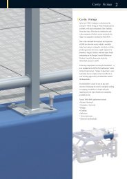
2 Cavity Fix<strong>in</strong>gs<br />
Introduction . . . . . . . . . . . . . . . . . . . . . . . . . . . . . . . . . . . . . . . . . . . .40<br />
Type HB - Hollo-Bolt ® . . . . . . . . . . . . . . . . . . . . . . . . . . . . . . . . . . . .41<br />
Type LB 2 - L<strong>in</strong>dibolt 2 ® . . . . . . . . . . . . . . . . . . . . . . . . . . . . . . . . . . .44<br />
Typical Applications . . . . . . . . . . . . . . . . . . . . . . . . . . . . . . . . . . . . . .45<br />
1 <strong>Steelwork</strong> Fix<strong>in</strong>gs<br />
Introduction . . . . . . . . . . . . . . . . . . . . . . . . . . . . . . . . . . . . . . . . . . . . .8<br />
Girder Clamps . . . . . . . . . . . . . . . . . . . . . . . . . . . . . . . . . . . . . . . . . .10<br />
Bolt Length / Tail Length / Installation . . . . . . . . . . . . . . . . . . . . . . . .11<br />
Type A . . . . . . . . . . . . . . . . . . . . . . . . . . . . . . . . . . . . . . . . . . . . . . . .12<br />
Type B . . . . . . . . . . . . . . . . . . . . . . . . . . . . . . . . . . . . . . . . . . . . . . . .13<br />
Accessories for Type A and B . . . . . . . . . . . . . . . . . . . . . . . . . . . . . .14<br />
Plate and Pack<strong>in</strong>g Details for Type A and B . . . . . . . . . . . . . . . . . . . .15<br />
Type AF . . . . . . . . . . . . . . . . . . . . . . . . . . . . . . . . . . . . . . . . . . . . . . .16<br />
Type CF . . . . . . . . . . . . . . . . . . . . . . . . . . . . . . . . . . . . . . . . . . . . . . .17<br />
Accessories for Type AF . . . . . . . . . . . . . . . . . . . . . . . . . . . . . . . . . .18<br />
Plate and Pack<strong>in</strong>g Details for Type AF and CF . . . . . . . . . . . . . . . . . .19<br />
Type LR . . . . . . . . . . . . . . . . . . . . . . . . . . . . . . . . . . . . . . . . . . . . . . .20<br />
Type D2 and Type D3 . . . . . . . . . . . . . . . . . . . . . . . . . . . . . . . . . . . .21<br />
Accessories for Type LR, D2 and D3 . . . . . . . . . . . . . . . . . . . . . . . . .22<br />
Plate and Pack<strong>in</strong>g Details for Type LR, D2 and D3 . . . . . . . . . . . . . . .23<br />
Type LS . . . . . . . . . . . . . . . . . . . . . . . . . . . . . . . . . . . . . . . . . . . . . . .24<br />
Accessories / Plate and Pack<strong>in</strong>g Details for Type LS . . . . . . . . . . . . .25<br />
Type BR and Type RC . . . . . . . . . . . . . . . . . . . . . . . . . . . . . . . . . . . .26<br />
Accessories / Plate and Pack<strong>in</strong>g Details for Type BR . . . . . . . . . . . . .27<br />
Type L<strong>in</strong>dapter-HD . . . . . . . . . . . . . . . . . . . . . . . . . . . . . . . . . . . . . . .28<br />
Type BSNT and Type BSLN . . . . . . . . . . . . . . . . . . . . . . . . . . . . . . . .30<br />
Type F9 and Type HW/HC . . . . . . . . . . . . . . . . . . . . . . . . . . . . . . . . .31<br />
Type SC and Type LP . . . . . . . . . . . . . . . . . . . . . . . . . . . . . . . . . . . .32<br />
Type FC . . . . . . . . . . . . . . . . . . . . . . . . . . . . . . . . . . . . . . . . . . . . . . .33<br />
Loads and Specifications . . . . . . . . . . . . . . . . . . . . . . . . . . . . . . . . . .34<br />
<strong>Technical</strong> Enquiry Fax . . . . . . . . . . . . . . . . . . . . . . . . . . . . . . . . . .35<br />
Typical Applications . . . . . . . . . . . . . . . . . . . . . . . . . . . . . . . . . . . . . .36<br />
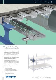
3 Composite Deck<strong>in</strong>g Fix<strong>in</strong>gs<br />
Introduction . . . . . . . . . . . . . . . . . . . . . . . . . . . . . . . . . . . . . . . . . . . .46<br />
Type AW - Alphawedge . . . . . . . . . . . . . . . . . . . . . . . . . . . . . . . . . . .47<br />
Type MW2 - Multiwedge 2 . . . . . . . . . . . . . . . . . . . . . . . . . . . . . . . . .48<br />
Type TR60 and Type VN - V-Nut . . . . . . . . . . . . . . . . . . . . . . . . . . . .49<br />
Type SD2 - Slimdek 2 . . . . . . . . . . . . . . . . . . . . . . . . . . . . . . . . . . . .50<br />
Type TC - Toggle Clamp . . . . . . . . . . . . . . . . . . . . . . . . . . . . . . . . . .51<br />
Deck<strong>in</strong>g Fix<strong>in</strong>gs Guide . . . . . . . . . . . . . . . . . . . . . . . . . . . . . . . . . . . .52<br />
4<br />
Tel: +44 (0) 1274 521444 www.l<strong>in</strong>dapter.com
4 Support Fix<strong>in</strong>gs<br />
Introduction . . . . . . . . . . . . . . . . . . . . . . . . . . . . . . . . . . . . . . . . . . . .54<br />
Type FLS . . . . . . . . . . . . . . . . . . . . . . . . . . . . . . . . . . . . . . . . . . . . . .55<br />
Type FL . . . . . . . . . . . . . . . . . . . . . . . . . . . . . . . . . . . . . . . . . . . . . . .56<br />
Type LC and Type SW - Swivel Unit . . . . . . . . . . . . . . . . . . . . . . . . . .57<br />
Type F3 and Type F3-BICC . . . . . . . . . . . . . . . . . . . . . . . . . . . . . . . .58<br />
Type SH and Type HW / HC . . . . . . . . . . . . . . . . . . . . . . . . . . . . . . .59<br />
Type Z10 and Type HCW30 . . . . . . . . . . . . . . . . . . . . . . . . . . . . . . . .60<br />
Type HCW31 and Type WF . . . . . . . . . . . . . . . . . . . . . . . . . . . . . . . .61<br />
Type HCW34 . . . . . . . . . . . . . . . . . . . . . . . . . . . . . . . . . . . . . . . . . . .62<br />
Purl<strong>in</strong> Profiles . . . . . . . . . . . . . . . . . . . . . . . . . . . . . . . . . . . . . . . . . . .62<br />
Typical Applications . . . . . . . . . . . . . . . . . . . . . . . . . . . . . . . . . . . . . .63<br />
6 Appendix<br />
Section Details . . . . . . . . . . . . . . . . . . . . . . . . . . . . . . . . . . . . . . . . .68<br />
General Enquiries . . . . . . . . . . . . . . . . . . . . . . . . . . . . . . . . . . . . . .70<br />
Projects . . . . . . . . . . . . . . . . . . . . . . . . . . . . . . . . . . . . . . . . . . . . . . .71<br />
Factors of safety shown <strong>in</strong> this catalogue are typical values and<br />
vary with different products from 2:1 to 5:1.<br />
Stated tighten<strong>in</strong>g torques must not be exceeded.<br />
Disclaimer<br />
L<strong>in</strong>dapter International supplies components <strong>in</strong> good faith, on the<br />
assumption that customers fully understand the load<strong>in</strong>gs, safety factors<br />
and physical parameters of the products <strong>in</strong>volved. Customers or users<br />
who are unaware or unsure of any details should refer to L<strong>in</strong>dapter<br />
International before use. Responsibility for loss, damage, or other<br />
consequences of mis-use cannot be accepted. L<strong>in</strong>dapter makes every<br />
effort to ensure that technical specifications and other product<br />
descriptions are correct. ‘Specification’ shall mean the specification<br />
(relat<strong>in</strong>g to the use of the materials) set out <strong>in</strong> the quotation given by the<br />
Seller to the Buyer. Responsibility for errors or omissions cannot be<br />
accepted. All dimensions stated are subject to production tolerances -<br />
if <strong>in</strong> doubt please check with L<strong>in</strong>dapter.<br />
5 Floor Fix<strong>in</strong>gs<br />
Introduction . . . . . . . . . . . . . . . . . . . . . . . . . . . . . . . . . . . . . . . . . . . .64<br />
Type FF - Floorfast ® . . . . . . . . . . . . . . . . . . . . . . . . . . . . . . . . . . . . . .65<br />
Type GF - Grate-Fast ® . . . . . . . . . . . . . . . . . . . . . . . . . . . . . . . . . . . .66<br />
Type GF3030 . . . . . . . . . . . . . . . . . . . . . . . . . . . . . . . . . . . . . . . . . . .67<br />
Applications<br />
All the applications featured <strong>in</strong> the catalogue are based on real<br />
projects. More <strong>in</strong>formation about these can be found on our website<br />
www.l<strong>in</strong>dapter.com.<br />
© L<strong>in</strong>dapter 2009 © L<strong>in</strong>dapter International<br />
© L<strong>in</strong>dapter is a registered trade mark<br />
In the <strong>in</strong>terests of improv<strong>in</strong>g the quality and performance of L<strong>in</strong>dapter<br />
products, we reserve the right to make specification changes without<br />
prior notice.<br />
Tel: +44 (0) 1274 521444 www.l<strong>in</strong>dapter.com<br />
5
Service and Support<br />
Research and Development<br />
To meet the needs of a fast chang<strong>in</strong>g world L<strong>in</strong>dapter’s Research and<br />
Development Department works to develop new generic products.<br />
The team is supported by the latest computer aided design (CAD)<br />
techniques such as 3D modell<strong>in</strong>g, rapid prototyp<strong>in</strong>g and f<strong>in</strong>ite element<br />
analysis; new products are tested <strong>in</strong> house on L<strong>in</strong>dapter’s own 1,000kN<br />
hydraulic test mach<strong>in</strong>e.<br />
This unique technical expertise is supported by L<strong>in</strong>dapter’s collaboration<br />
with respected companies and organisations such as Corus, Mannesmann,<br />
The Steel Construction Institute, CIDECT as well as many lead<strong>in</strong>g<br />
universities and approval bodies.<br />
Eng<strong>in</strong>eered Solutions<br />
Develop<strong>in</strong>g products that meet the needs of a particular project is<br />
another L<strong>in</strong>dapter strength.<br />
The service offered to clients <strong>in</strong>cludes:<br />
• Design and development of custom products for unique projects<br />
• Individual test runs and reports<br />
• Detailed draw<strong>in</strong>gs and/or solid models<br />
• Full strength and performance analysis<br />
• Trial runs and on site consultation<br />
Bespoke solution<br />
for sign fix<strong>in</strong>gs<br />
Customer <strong>Technical</strong> Support<br />
For our exist<strong>in</strong>g product range L<strong>in</strong>dapter’s <strong>Technical</strong> Sales and Support<br />
Department offers customers full support for any project, large or small;<br />
this free of charge service <strong>in</strong>cludes:<br />
• Assembly solutions optimised for cost and performance<br />
• Load analysis on L<strong>in</strong>dapter connections<br />
• 2D AutoCAD and 3D SolidWorks draw<strong>in</strong>gs<br />
• Bills of Materials<br />
• Coat<strong>in</strong>g and corrosion recommendations<br />
• On site technical advice and support<br />
• Contractor tra<strong>in</strong><strong>in</strong>g<br />
• CPD Presentations<br />
Sample Project<br />
Seedhill Bridge, Lancashire, England<br />
Bridge refurbishment:<br />
Due to the age and condition of the structure the use of welded shear<br />
studs was not possible. Instead modified Hollo-Bolts ® were used which<br />
enabled the bridge deck refurbishment to be completed on time and to<br />
specification.<br />
Special Hollo-Bolt ®<br />
For further <strong>in</strong>formation regard<strong>in</strong>g this project see website<br />
www.l<strong>in</strong>dapter.com.<br />
Standard Hollo-Bolt ®<br />
6<br />
Tel: +44 (0) 1274 521444 www.l<strong>in</strong>dapter.com
Quality and Approvals<br />
Quality<br />
Product quality is one of the ma<strong>in</strong> life l<strong>in</strong>es<br />
of the L<strong>in</strong>dapter philosophy, the entire<br />
company is particularly dedicated to this<br />
aspect. L<strong>in</strong>dapter has been accredited to<br />
BS EN ISO 9001 s<strong>in</strong>ce 1986.<br />
Approvals<br />
L<strong>in</strong>dapter has been trad<strong>in</strong>g <strong>in</strong>ternationally for many years respect<strong>in</strong>g<br />
the market differences around the world. The relevant <strong>in</strong>ternational<br />
authorities have granted many product approvals over time.<br />
The catalogue refers to them product by product.<br />
Approvals for construction<br />
The Deutsches Institut für Bautechnik, Berl<strong>in</strong> is a body<br />
which approves products and materials for use <strong>in</strong><br />
structural eng<strong>in</strong>eer<strong>in</strong>g applications <strong>in</strong> the construction<br />
and civil eng<strong>in</strong>eer<strong>in</strong>g <strong>in</strong>dustries <strong>in</strong> Germany.<br />
Lloyds Register Type Approved products have been<br />
subjected to tensile, frictional, shear, vibration and<br />
shock tests, witnessed and verified by Lloyds<br />
Register.<br />
The TÜV is the certify<strong>in</strong>g authority for safety,<br />
quality and environmental protection <strong>in</strong> Germany.<br />
Det Norske Veritas has approved the use of L<strong>in</strong>dapter<br />
products <strong>in</strong> lift<strong>in</strong>g applications. This <strong>in</strong>cludes their use<br />
on both mobile and fixed offshore <strong>in</strong>stallations.<br />
Q 05143<br />
Approvals for spr<strong>in</strong>kler products<br />
The American Insurance Association, Factory Mutual,<br />
offers an approval which is recognised by the fire<br />
protection <strong>in</strong>dustry world-wide.<br />
Verband der Schadenversicherer e.V. is a German<br />
<strong>in</strong>surance association who also offers a rigorous<br />
approval for products used <strong>in</strong> the fire protection<br />
<strong>in</strong>dustry.<br />
These approvals serve to re<strong>in</strong>force L<strong>in</strong>dapter’s extensive <strong>in</strong>-house<br />
test<strong>in</strong>g procedures. L<strong>in</strong>dapter products are tested so that the user can<br />
be confident whether specify<strong>in</strong>g or us<strong>in</strong>g that L<strong>in</strong>dapter products will<br />
perform as per the <strong>in</strong>formation detailed <strong>in</strong> this catalogue. Loads<br />
published are the product safe work<strong>in</strong>g loads, tak<strong>in</strong>g <strong>in</strong>to account a<br />
factor of safety.<br />
Corrosion Protection<br />
L<strong>in</strong>dapter products are delivered as standard either bright z<strong>in</strong>c plated<br />
or hot dip galvanised. Various other coat<strong>in</strong>gs and alternative materials<br />
are available upon request for most products <strong>in</strong>clud<strong>in</strong>g:<br />
• Sheradis<strong>in</strong>g<br />
• Mechanical galvanis<strong>in</strong>g<br />
• Plastic coat<strong>in</strong>g<br />
• Special pa<strong>in</strong>t coat<strong>in</strong>g<br />
• Delta seal<br />
• Delta tone<br />
• Sheraplex<br />
• Sta<strong>in</strong>less steel<br />
L<strong>in</strong>dapter is a member of the follow<strong>in</strong>g organisations:<br />
British Constructional<br />
<strong>Steelwork</strong> Association<br />
The Steel Construction<br />
Institute<br />
The Build<strong>in</strong>g Services Research<br />
and Information Association<br />
Tel: +44 (0) 1274 521444 www.l<strong>in</strong>dapter.com<br />
7
<strong>Steelwork</strong> Fix<strong>in</strong>gs 1<br />
<strong>Steelwork</strong> Fix<strong>in</strong>gs<br />
L<strong>in</strong>dapter <strong>Steelwork</strong> Fix<strong>in</strong>gs can be used <strong>in</strong> a wide<br />
variety of applications for connect<strong>in</strong>g together steel<br />
sections of whatever shape and size; uppermost <strong>in</strong><br />
this section is the Girder Clamp which, as with<br />
most L<strong>in</strong>dapter products, needs no on site drill<strong>in</strong>g<br />
or weld<strong>in</strong>g sav<strong>in</strong>g both time and money by reduc<strong>in</strong>g<br />
<strong>in</strong>stalled costs. Numerous world wide project<br />
successes have demonstrated that this is ideally<br />
suited for both new construction and refurbishment<br />
of exist<strong>in</strong>g structures.<br />
Advantages<br />
• Reduces design time<br />
• Guaranteed loads and approvals<br />
• No on-site drill<strong>in</strong>g or weld<strong>in</strong>g<br />
• ‘Hot Work<strong>in</strong>g’ not required<br />
• Less work at height<br />
• Only hand tools required to <strong>in</strong>stall<br />
• Site adjustable<br />
• Power not required<br />
• Ability to deconstruct and multi-cycle<br />
rather than demolish<br />
Markets <strong>in</strong>clude:<br />
• Plant Eng<strong>in</strong>eer<strong>in</strong>g<br />
• Chemical and Petro-chemical Industry<br />
• Materials Handl<strong>in</strong>g<br />
• Structural Eng<strong>in</strong>eer<strong>in</strong>g<br />
• Civil Eng<strong>in</strong>eer<strong>in</strong>g<br />
• Facades<br />
• Theatre Equipment<br />
• Transportation<br />
• Offshore<br />
Applications <strong>in</strong>clude:<br />
• Steel Constructions<br />
• Cranes<br />
• Lift<strong>in</strong>g Beams<br />
• Pipe Supports<br />
• Towers and Masts<br />
9
Girder Clamps <strong>Steelwork</strong> Fix<strong>in</strong>gs 1<br />
Components of a Girder Clamp<br />
1. Standard Grade 8 Hex Nut<br />
2. Standard Hardened Washer<br />
3. L<strong>in</strong>dapter Clamp<br />
Dependent on the application different clamps could be used i.e.<br />
Types A, B, BR, AF, LR, LS, D2 or D3.<br />
4. Pack<strong>in</strong>g Piece<br />
In comb<strong>in</strong>ation with the clamps mentioned above these parts<br />
<strong>in</strong>crease the tail length to enable the product to sit correctly on the<br />
beam.<br />
5. Location Plate (can be supplied if required)<br />
This is an essential part of the girder clamp assembly that enables<br />
all the components to be located <strong>in</strong> the correct position. The hole<br />
centres and plate thickness are calculated to suit the <strong>in</strong>dividual<br />
application.<br />
6. L<strong>in</strong>dapter Clamp<br />
This can be of a similar type as 3 (above), although certa<strong>in</strong> products<br />
are designed to specifically work together i.e. A + B.<br />
7. Standard Grade 8.8 Hex Bolt or Setscrew<br />
5<br />
1<br />
2<br />
3<br />
4<br />
Loads<br />
The table beneath shows tensile and frictional load capabilities for a<br />
standard four bolt Girder Clamp us<strong>in</strong>g 4 bolts and 8 clamps at a 90°<br />
crossover angle. L<strong>in</strong>dapter is only too pleased to carry out all design work<br />
for <strong>in</strong>dividual connections free of charge based on the follow<strong>in</strong>g details:<br />
• Load per connection<br />
• Size and type of both beams<br />
• Angle of crossover<br />
• Distance between beams<br />
• Incl<strong>in</strong>ation of beams<br />
6<br />
7<br />
Clamps Types A, B, BR, LR Type AF<br />
Bolt size M12 M16 M20 M24 M24 M24<br />
Bolt grade 8.8 8.8 8.8 8.8 8.8 10.9<br />
Tensile / for 4 bolts kN 23.2 29.2 59.0 78.8 160.0 250.0 1)<br />
Friction / for 4 bolts kN 1.4 3.0 6.0 9.0 60.0 2) 70.0 2)<br />
Torque Nm 69 147 285 491 800 1000<br />
1) Factor of safety 3.2:1<br />
2) Factor of safety 2:1<br />
All loads are based on actual test data hav<strong>in</strong>g a factor of safety for friction aga<strong>in</strong>st slip and for tensile aga<strong>in</strong>st ultimate failure<br />
(typically 5:1). Use of lower safety factor is not recommended.<br />
Approvals<br />
All approvals apply to Girder Clamps us<strong>in</strong>g types A and B only, <strong>in</strong> sizes from M12 to M24 Further <strong>in</strong>formation is available upon request.<br />
10<br />
Tel: +44 (0) 1274 521444 www.l<strong>in</strong>dapter.com
Bolt Length / Tail Length / Installation <strong>Steelwork</strong> Fix<strong>in</strong>gs 1<br />
Bolt length calculation for a<br />
standard L<strong>in</strong>dapter Girder Clamp,<br />
example shows Type A and B M20<br />
Tail length<br />
The different tail length can be identified by a code of dimples<br />
underneath the clamps.<br />
To calculate the bolt length all parts the bolt will go through have to<br />
be added up. The next longer standard bolt length should be used.<br />
0.5 · bolt Ø<br />
as bolt protrusion<br />
10<br />
One dimple:<br />
tail length short (s)<br />
Height of nut<br />
16<br />
+ Washer<br />
3<br />
+ T of top clamp<br />
+ Top section<br />
20<br />
12.5<br />
Two dimples:<br />
tail length medium (m)<br />
+ Plate thickness<br />
12<br />
+ Lower section<br />
10<br />
+ T of lower clamp<br />
10<br />
Three dimples:<br />
tail length long (l )<br />
=<br />
93.5<br />
Next standard<br />
bolt length<br />
=<br />
100.0<br />
Correct <strong>in</strong>stallation of types A and B<br />
show<strong>in</strong>g type A as an example<br />
Parallel flanges<br />
90º 90º<br />
Maximum tail length tolerance of -1mm (up to M16) and -1.5mm (M20, M24) before apply<strong>in</strong>g the torque is acceptable.<br />
Tapered flanges<br />
90º<br />
Type A <strong>Steelwork</strong> Fix<strong>in</strong>gs 1<br />
Type A<br />
Malleable iron, bright z<strong>in</strong>c plated / hot dip galvanised<br />
Nose<br />
Recess<br />
Clamp<strong>in</strong>g Area K<br />
Skirt<br />
Tail<br />
T<br />
V<br />
Y<br />
X<br />
Z<br />
Typical Applications<br />
(see also page 36-39)<br />
<strong>Steelwork</strong> clamp with recessed top to hold the bolt head captive whilst<br />
the nut is tightened. The skirt prevents the clamp rotat<strong>in</strong>g dur<strong>in</strong>g<br />
<strong>in</strong>stallation. Suitable for flanges up to 8°.<br />
The clamp is <strong>in</strong>stalled correctly when the area ‘K’ grips the flange.<br />
The tail must be chosen to suit the thickness of the flange be<strong>in</strong>g<br />
gripped. For correct tail length/pack<strong>in</strong>g comb<strong>in</strong>ations please see<br />
page 15.<br />
Safe Work<strong>in</strong>g Loads<br />
Dimensions<br />
Product Bolt 8.8 (5:1 Factor of Safety) Tail Length V<br />
Code Z Tensile / 1 Bolt Frictional / 2 Bolts Torque Y X short medium long T Width<br />
kN kN Nm mm mm mm mm mm mm mm<br />
A08 M8 1.0 - 6 16 8 - 4 - 4 20<br />
A10 M10 1.5 - 20 20 11 4 5 7 5 26<br />
A12 M12 5.8 0.7 69 26 13 4.5 6 9.5 6 29<br />
A16 M16 7.3 1.5 147 30 16 5.5 8 11 8 36<br />
A20 M20 14.7 3 285 36 19 7 10 12.5 10 46<br />
A24 M24 19.7 4.5 491 48 25 9 12 16 12 55<br />
For higher loads the type AF should be used (see page 16).<br />
Order example: A16 medium HDG<br />
12<br />
Tel: +44 (0) 1274 521444 www.l<strong>in</strong>dapter.com
Type B <strong>Steelwork</strong> Fix<strong>in</strong>gs 1<br />
Type B<br />
Malleable iron, bright z<strong>in</strong>c plated / hot dip galvanised<br />
Nose<br />
Flat Top<br />
Clamp<strong>in</strong>g<br />
Area K<br />
Skirt<br />
Tail<br />
Z<br />
T<br />
V<br />
Y<br />
X<br />
<strong>Steelwork</strong> clamp with flat top which allows the bolt head or<br />
nut to be rotated. Suitable for use with all bolts, studs, tie<br />
rods and J-bolts, and flanges up to 8°.<br />
The clamp is <strong>in</strong>stalled correctly when the area ‘K’ grips the<br />
flange. The tail must be chosen to suit the thickness of the<br />
flange be<strong>in</strong>g gripped. For correct tail length/pack<strong>in</strong>g<br />
comb<strong>in</strong>ations please see page 15.<br />
Typical Applications<br />
(see also page 36-39)<br />
Safe Work<strong>in</strong>g Loads<br />
Dimensions<br />
Product Bolt 8.8 (5:1 Factor of Safety) Tail Length V<br />
Code Z Tensile / 1 Bolt Frictional / 2 Bolts Torque Y X short medium long T Width<br />
kN kN Nm mm mm mm mm mm mm mm<br />
B08 M8 1.0 - 6 16 8 - 4 - 8 20<br />
B10 M10 1.5 - 20 20 11 4 5 7 10 26<br />
B12 M12 5.8 0.7 69 26 13 4.5 6 9.5 12 29<br />
B16 M16 7.3 1.5 147 30 16 5.5 8 11 16 36<br />
B20 M20 14.7 3 285 36 19 7 10 12.5 20 46<br />
B24 M24 19.7 4.5 491 48 25 9 12 16 24 55<br />
For higher loads the type AF should be used (see page 16).<br />
Order example: B16 medium HDG<br />
Tel: +44 (0) 1274 521444 www.l<strong>in</strong>dapter.com<br />
13
Accessories for Type A and B <strong>Steelwork</strong> Fix<strong>in</strong>gs 1<br />
Type CW - Clipped Washer<br />
Mild Steel, bright z<strong>in</strong>c plated /<br />
hot dip galvanised<br />
Pack<strong>in</strong>g used to adjust the tail length of the clamp to meet<br />
differ<strong>in</strong>g beam flange thicknesses.<br />
Y<br />
Z<br />
X<br />
T<br />
Product Bolt Dimensions<br />
Code Z Y X T Width<br />
mm mm mm mm<br />
CW08 M8 4 9,5 2 19<br />
CW10 M10 5 14 2 25<br />
CW12 M12 6 19.5 2.5 31<br />
CW16 M16 8 17.5 3 38<br />
CW20 M20 10 22 4 44<br />
CW24 M24 12 29 4 57<br />
Order example: CW08 BZP<br />
Type P1 short / P2 short<br />
Mild Steel, malleable iron,<br />
bright z<strong>in</strong>c plated / hot dip galvanised<br />
Pack<strong>in</strong>g used to adjust the tail length of the clamp to meet<br />
differ<strong>in</strong>g beam flange thicknesses.<br />
Y<br />
Z<br />
T P1<br />
T P2<br />
X<br />
Product Bolt Dimensions<br />
Code Z Y X T P1 T P2 Width<br />
P1 P2 mm mm mm mm mm<br />
P1S08 P2S08 M8 4 10 4 8 21<br />
P1S10 P2S10 M10 5 13 5 10 24<br />
P1S12 P2S12 M12 6 16 6 12 30<br />
P1S16 P2S16 M16 8 21 8 16 35<br />
P1S20 P2S20 M20 10 23 10 20 43<br />
P1S24 P2S24 M24 12 32 12 24 54<br />
Order example: P1S16 HDG<br />
Type T<br />
Malleable iron, bright z<strong>in</strong>c plated /<br />
hot dip galvanised<br />
To fill the nose of type A and B mak<strong>in</strong>g it horizontal. For parallel flanges<br />
only. The thickness ‘T’ should be added for tail length and bolt length<br />
calculations. The product is for aesthetic purposes only and technically<br />
not necessary.<br />
Type W<br />
Mild Steel, malleable iron, bright z<strong>in</strong>c plated /<br />
hot dip galvanised<br />
Washer to fill the recess of type A to enable the nut to be tightened.<br />
When calculat<strong>in</strong>g the bolt length please add ‘T’.<br />
Z<br />
Z<br />
T<br />
T<br />
Product Bolt Dimensions<br />
Code Z T<br />
mm<br />
T12 M12 3<br />
T16 M16 4<br />
T20 M20 5<br />
T24 M24 6.5<br />
Order example: T12 BZP<br />
Product Bolt Dimensions<br />
Code Z T<br />
mm<br />
W08 M8 4<br />
W10 M10 5.5<br />
W12 M12 6.5<br />
W16 M16 8<br />
W20 M20 9.5<br />
Order example: W08 BZP<br />
14<br />
Tel: +44 (0) 1274 521444 www.l<strong>in</strong>dapter.com
Plate and Pack<strong>in</strong>g Details for Type A and B <strong>Steelwork</strong> Fix<strong>in</strong>gs 1<br />
Location and End Plates<br />
L 1<br />
L 1<br />
l 1M<br />
l 1M<br />
b 1 b 1<br />
L 1 =<br />
L 2 =<br />
l 1M , l 2M =<br />
b 1 , b 2 =<br />
d =<br />
s =<br />
Plate length<br />
Plate width<br />
Hole centres<br />
Flange width<br />
Hole Ø<br />
Plate thickness<br />
d<br />
b 2<br />
l 2M<br />
L 2<br />
l2M<br />
d<br />
L2<br />
Location Plate<br />
Plate Dimensions<br />
Material: Mild Steel Grade S275 JR (for other grades please contact L<strong>in</strong>dapter)<br />
End Plate<br />
Location Plate End Plate 1)<br />
Plate<br />
Plate<br />
Bolt Hole Ø Thickness Hole Centres Length/Width Thickness Hole Centre Length Hole Centre Width<br />
Z d s l 1M , l 2M m<strong>in</strong> L 1 , m<strong>in</strong> L 2 s l 1M m<strong>in</strong> L 1 m<strong>in</strong> l 2M m<strong>in</strong> L 2<br />
mm mm mm mm mm mm mm mm mm<br />
M8 9 6 b + 9 b + 36 10 b 1 + 9 b 1 + 36 40 l 2M + 40<br />
M10 11 8 b + 11 b + 44 12 b 1 + 11 b 1 + 44 50 l 2M + 40<br />
M12 13 8 b + 13 b + 54 12 b 1 + 13 b 1 + 54 60 l 2M + 50<br />
M16 18 10 b + 18 b + 70 15 b 1 + 18 b 1 + 70 70 l 2M + 60<br />
M20 22 12 b + 22 b + 88 20 b 1 + 22 b 1 + 88 90 l 2M + 70<br />
M24 26 15 b + 26 b + 104 25 b 1 + 26 b 1 + 104 110 l 2M + 90<br />
1) Dependant on the use of the end plate the thickness might need to be <strong>in</strong>creased.<br />
Calculation of bolt length see page 11<br />
Tail Length / Pack<strong>in</strong>g Comb<strong>in</strong>ations<br />
for Types A & B<br />
For beams up to and <strong>in</strong>clud<strong>in</strong>g 5° slope<br />
Flange<br />
Types A & B<br />
Thickness M12 M16 M20 M24<br />
mm A,B CW P1S P2S A,B CW P1S P2S A,B CW P1S P2S A,B CW P1S P2S<br />
5 s - - - s - - - - - - - - -<br />
6 m - - - s - - - - - - - - -<br />
7 s 1 - - m - - - s - - - - - -<br />
8 s 1 - - m - - - s - - - - - -<br />
9 m 1 - - s 1 - - m - - - s - - -<br />
10 l - - - l - - - m - - - s - - -<br />
11 m 2 - - l - - - s 1 - - m - - -<br />
12 l 1 - - s 2 - - s 1 - - m - - -<br />
1 3 s 1 1 - l - - - ss - 1 1 - - -<br />
14 s 1 1 - l 1 - - m 1 - - s 1 - -<br />
15 l 2 - - s 3 - - s 2 - - l - - -<br />
16 l - 1 - m - 1 - s 2 - - l - - -<br />
17 m 2 1 - l 2 - - s - 1 - s 2 - -<br />
18 m - - 1 l 2 - - m 2 - - s 2 - -<br />
1 9 s 1 - 1 l - 1 - s 3 - - l 1 - -<br />
2 0 s 1 - 1 l 3 - - m - 1 - l 1 - -<br />
2 1 m 1 - 1 l 3 - - s 1 1 - s - 1 -<br />
22 l - - 1 l 1 1 - m 3 - - s - 1 -<br />
23 s - 1 1 l 1 1 - l - 1 - m - 1 -<br />
Tail Length / Pack<strong>in</strong>g Comb<strong>in</strong>ations<br />
for Types A & B<br />
For IPN-Beams of an 8° slope<br />
Types A & B<br />
IPN M12 M16 M20 M24<br />
Profile A,B CW P1S P2S A,B CW P1S P2S A,B CW P1S P2S A,B CW P1S P2S<br />
80 - - - - - - - - - - - -<br />
100 - - - - - - - - - - - -<br />
120 s - - - - - - - - - - - -<br />
140 s - - - - - - - - - - - -<br />
1 6 0 m - - - s - - - - - -<br />
1 8 0 m - - - s - - - - - -<br />
200 s 1 - - - - - - - - - - -<br />
220 s 1 - - - - - - - - - - -<br />
2 4 0 m 1 - - m - - - s - - -<br />
2 6 0 m 1 - - m - - - s - - -<br />
280 l - - - - - - - - - s - - -<br />
300 s - 1 - - - - m - - - s - - -<br />
320 m 2 - - l - - - m - - - s - - -<br />
340 l 1 - - l - - - s 1 - - - - -<br />
360 s 1 1 - - - - l - - - m - - -<br />
380 m 3 - - s - 1 - l - - - m - - -<br />
400 l 2 - - l 1 - - - - - s 1 - -<br />
425 - - - m - 1 - - - - - - -<br />
450 - - - m - 1 - - - - - - -<br />
475 - - - - - - - - - l - - -<br />
500 - - - - - - - - - l - - -<br />
550 - - - - - - - - - - - -<br />
600 - - - - - - - - - - - -<br />
2 4 m - 1 1 m - - 1 m 1 1 - m - 1 -<br />
2 5 s 1 1 1 l 2 1 - s 2 1 - s 1 1 -<br />
2 6 s 1 1 1 l 2 1 - s 2 1 - s 1 1 -<br />
28 l - 1 1 s 2 - 1 m 2 1 - l - 1 -<br />
30 m - - 2 l 1 - 1 m - - 1 s 2 1 -<br />
For thicker flanges please contact L<strong>in</strong>dapter.<br />
s = short m = medium l = long P1S = P1 short P2S = P2 short = Type not applicable = Please contact L<strong>in</strong>dapter<br />
Tel: +44 (0) 1274 521444 www.l<strong>in</strong>dapter.com<br />
15
Type AF <strong>Steelwork</strong> Fix<strong>in</strong>gs 1<br />
Type AF<br />
SG iron, hot dip galvanised<br />
Without washer: For bolt grade 8.8<br />
Recess<br />
Nose<br />
Skirt<br />
Tail<br />
With washer Type AFW<br />
Flat Top<br />
T<br />
V<br />
Y<br />
X<br />
With washer <strong>in</strong>verted Type AFW<br />
for bolt grade 10.9 with larger hexagons<br />
(M12 - M20)<br />
Z<br />
Typical Applications<br />
(see also page 36-39)<br />
High friction clamp with recessed top to hold bolt head captive whilst<br />
the nut is tightened. Can be comb<strong>in</strong>ed with type CF. The skirt prevents<br />
the clamp rotat<strong>in</strong>g dur<strong>in</strong>g <strong>in</strong>stallation. The tail of the AF spans across<br />
slotted holes. For flanges up to 10°. Washer type AFW available<br />
(see illustration).<br />
For correct tail length/pack<strong>in</strong>g comb<strong>in</strong>ations please see page 18.<br />
Safe Work<strong>in</strong>g Loads<br />
(5:1) Factor of Safety (2:1) Dimensions<br />
Product Bolt Tensile / 1 Bolt Frictional 1) / 2 Bolts Tail Length V T<br />
Code Z Grade Pa<strong>in</strong>ted <strong>Steelwork</strong> 2) Galv. <strong>Steelwork</strong> Torque Y X short medium Type AF Type AF with AFW Width<br />
kN kN kN Nm mm mm mm mm mm mm mm<br />
AF12 M12 8.8 8.5 3.4 3.9 90 29 27 5 12.5 17 22 39<br />
AF16 M16 8.8 16.0 8.0 10.0 240 35 37 8 15 22 27 49<br />
AF20 M20 8.8 26.3 13.0 16.0 470 40 39 10 18 25 31 56<br />
AF24 M24 8.8 40.0 24.0 30.0 800 48 60 15 30 32 42 82<br />
AF12 M12 10.9 4) 10.0 4.0 5.2 130 29 27 5 12.5 17 22 39<br />
AF16 M16 10.9 4) 19.5 11.0 12.0 300 35 37 8 15 22 27 49<br />
AF20 M20 10.9 4) 30.0 20.0 25.0 647 40 39 10 18 25 31 56<br />
AF24 M24 10.9 4) 62.5 3) 28.0 35.0 1000 48 60 15 30 32 42 82<br />
1) Frictional Load figures are based on Type AF and Location plates <strong>in</strong> hot dip galvanised f<strong>in</strong>ish<br />
2) Shot blast and pa<strong>in</strong>ted steelwork<br />
3) 3.2:1 factor of safety<br />
4) For HR or HV bolts (hot dip galvanised and lubricated) please refer to manufacturers’ recommendation for torque figures.<br />
Order example: AF12 short<br />
16<br />
Tel: +44 (0) 1274 521444 www.l<strong>in</strong>dapter.com
Type CF <strong>Steelwork</strong> Fix<strong>in</strong>gs 1<br />
Type CF<br />
SG iron, hot dip galvanised<br />
Nose<br />
Anti-rotation mark<strong>in</strong>gs<br />
Legs<br />
Y<br />
X<br />
Y<br />
X<br />
m<strong>in</strong> T<br />
max T<br />
V<br />
m<strong>in</strong> t<br />
Z<br />
max t<br />
Z<br />
Typical Applications<br />
(see also page 36-39)<br />
High friction clamp which hooks over flanges of I-beams, angles and<br />
channels. L<strong>in</strong>dapter mark<strong>in</strong>gs act as a unique anti-rotation device.<br />
Can be comb<strong>in</strong>ed with all L<strong>in</strong>dapter Girder Clamp products <strong>in</strong>clud<strong>in</strong>g<br />
type AF.<br />
Safe Work<strong>in</strong>g Loads<br />
(5:1) factor of safety (2:1)<br />
Product Bolt 8.8 Tensile / 1 Bolt Frictional 1) / 2 Bolts Dimensions<br />
Code Z Pa<strong>in</strong>ted <strong>Steelwork</strong> 2) Galv. <strong>Steelwork</strong> Torque Y X t T V Width<br />
kN kN kN Nm mm mm mm mm mm mm<br />
CF12 M12 8.5 3.4 3.9 90 32 14 6 - 13 21 - 29 25 46<br />
CF16 M16 16.0 8.0 10.0 240 44 18 8 - 16 25 - 33 32 56<br />
CF20 M20 26.3 13.0 16.0 470 53 22 10 - 19 30 - 41 45 65<br />
CF Comb<strong>in</strong>ations with other L<strong>in</strong>dapter Clamps<br />
kN kN kN Nm<br />
CF / A 3) M12 5.8 0.7 0.7 69<br />
CF / A 3) M16 7.3 1.5 1.7 147<br />
CF / A 3) M20 14.7 3 3.0 285<br />
CF / AF M12 8.5 3.4 3.9 90<br />
CF / AF M16 16.0 8.0 10.0 240<br />
CF / AF M20 26.3 13.0 16.0 470<br />
Order example: CF12<br />
1) Frictional load figures are based on type CF and location plate <strong>in</strong> HDG f<strong>in</strong>ish<br />
2) Shot blast and pa<strong>in</strong>ted steelwork<br />
3) Also applies to type B, BR, LR, D2 or D3<br />
Tel: +44 (0) 1274 521444 www.l<strong>in</strong>dapter.com<br />
17
Accessories for Type AF <strong>Steelwork</strong> Fix<strong>in</strong>gs 1<br />
Type AFCW<br />
Mild Steel, hot dip galvanised<br />
Product Bolt Dimensions<br />
Code Z Y X T Width<br />
mm mm mm mm<br />
AF12CW M12 7 33 2 40<br />
T<br />
AF16CW M16 8 40 2 50<br />
Y<br />
X<br />
AF20CW M20 9.5 40.5 2 55<br />
Pack<strong>in</strong>g used to adjust the tail length of<br />
the clamp to meet differ<strong>in</strong>g beam flange<br />
thicknesses; has a slight bend along its<br />
centre l<strong>in</strong>e which flattens out dur<strong>in</strong>g<br />
<strong>in</strong>stallation.<br />
Z<br />
Order example: AF12CW<br />
Type AFP1 / AFP2<br />
Mild Steel, hot dip galvanised<br />
Product Bolt Dimensions<br />
Y<br />
X<br />
T<br />
Code Z Y X T P1 T P2 Width<br />
P1 P2 mm mm mm mm mm<br />
AF12P1 AF12P2 M12 7 33 5 10 40<br />
AF16P1 AF16P2 M16 8 42 5 10 52<br />
Z<br />
AF20P1 AF20P2 M20 9.5 45.5 5 10 56<br />
AF24P1 AF24P2 M24 12 73 5 10 85<br />
Pack<strong>in</strong>g used to adjust the tail<br />
length of the clamp to meet<br />
differ<strong>in</strong>g beam flange thicknesses.<br />
Order example: AF12P1<br />
Type AFW<br />
SG iron, malleable iron, hot dip galvanised<br />
Z<br />
T<br />
Product Bolt Dimensions<br />
Code Z T<br />
mm<br />
AFW12 M12 5<br />
AFW16 M16 5<br />
AFW20 M20 6<br />
AFW24 M24 10<br />
Washer fill<strong>in</strong>g the recess of the type AF.<br />
Additionally it features two projections<br />
which, when the AFW is <strong>in</strong>verted, will<br />
captivate the larger hexagons of 10.9<br />
bolts. (M12 – M20 only).<br />
T<br />
Order example: AFW12<br />
M24 version has no projections.<br />
Z<br />
18<br />
Tel: +44 (0) 1274 521444 www.l<strong>in</strong>dapter.com
Plate and Pack<strong>in</strong>g Details for Type AF and CF <strong>Steelwork</strong> Fix<strong>in</strong>gs 1<br />
Location and End Plates<br />
L 1<br />
L 1<br />
l 1M<br />
l 1M<br />
b 1 b 1<br />
L 1 =<br />
L 2 =<br />
l 1M , l 2M =<br />
b 1 , b 2 =<br />
d =<br />
s =<br />
Plate length<br />
Plate width<br />
Hole centres<br />
Flange width<br />
Hole Ø<br />
Plate thickness<br />
d<br />
b 2<br />
l 2M<br />
L 2 l2M L 2<br />
d<br />
Location Plate<br />
End Plate<br />
Plate Dimensions<br />
Material: Mild Steel Grade S355 JR (for other grades please contact L<strong>in</strong>dapter)<br />
Plate<br />
Location Plate End Plate 1)<br />
Bolt Hole Ø Thickness Hole Centres Length/Width Thickness Hole Centre Length Hole Centre Width<br />
Z d s l 1M , l 2M m<strong>in</strong> L 1 , m<strong>in</strong> L 2 s l 1M m<strong>in</strong> L 1 m<strong>in</strong> l 2M m<strong>in</strong> L 2<br />
mm mm mm mm mm mm mm mm mm<br />
M12 13 10 b + 13 b + 90 15 b 1 + 13 b 1 + 90 80 l 2M + 80<br />
M16 18 15 b + 18 b + 110 25 b 1 + 18 b 1 + 110 100 l 2M + 100<br />
M20 22 20 b + 22 b + 130 30 b 1 + 22 b 1 + 130 180 l 2M + 180<br />
M24 26 25 b + 26 b + 180 40 b 1 + 26 b 1 + 180 200 l 2M + 200<br />
1) Dependant on the use of the end plate the thickness might need to be <strong>in</strong>creased.<br />
2) For comb<strong>in</strong>ations of Type CF with A, B and BR see page 15 and for types D2, D3 and LR see page 23.<br />
Plate<br />
Calculation of bolt length see page 11<br />
Tail Length / Pack<strong>in</strong>g Comb<strong>in</strong>ations for Types AF<br />
Parallel flanges and beams of up to 10º slope<br />
Flange<br />
Type AF<br />
Thickness M12 M16 M20 M24<br />
mm AF AFCW AFP1 AFP2 AF AFCW AFP1 AFP2 AF AFCW AFP1 AFP2 AF AFP1 AFP2<br />
Flange<br />
Type AF<br />
Thickness M12 M16 M20 M24<br />
mm AF AFCW AFP1 AFP2 AF AFCW AFP1 AFP2 AF AFCW AFP1 AFP2 AF AFP1 AFP2<br />
5 s - - - - - - - - - - - 2 8 m - 1 1 s - - 2 m - - 1<br />
6 s - - - - - - - - - - - 2 9 m 1 1 1 m - 1 1 m - - 1 m - -<br />
7 s 1 - - s - - - - - - - - 3 0 s - 1 2 m - 1 1 m 1 - 1 m - -<br />
8 s 1 - - s - - - - - - - - 3 1 s - 1 2 m - 1 1 m 1 - 1 m -<br />
9 s 2 - - s - - - s - - - - - 3 2 m - - 2 m 1 1 1 m - 1 1 m 1<br />
1 0 s - 1 - s 1 - - s - - - 3 3 m- - - 2 m 1 1 1 m - 1 1 m 1<br />
1 1 s 3 - - s 1 - - s - - - 3 4 m- -1 - 2 m - - 2 m - 1 1 m 1 -<br />
1 2 s 1 1 - s 2 - - s 1 - - 3s 5- -s - - 3 m - - 2 s - 1 2 m 1 -<br />
1 3 m - - - s - 1 - s 1 - - s -3 -6 s - - 3 m - - 2 m 1 1 1 m 1 -<br />
1 4 m 1 - - s 3 - - s 2 - - s 3- 7-<br />
m - 1 2 m 1 - 2 m - - 2 m 1 -<br />
1 5 s - - 1 m - - - s - 1 - s - - 3 8 m - 1 2 s - - 3 m - - 2<br />
1 6 m 2 - - m - - - s 3 - - s - 3-<br />
9 m 1 1 2 m - 1 2 m - - 2 m -<br />
1 7 m - 1 - m 1 - - m - - - s - - 4 0 s - 1 3 m - 1 2 m 1 - 2 m - 1<br />
1 8 m - 1 - s - - 1 m - - - s 1 - 4 1 s - 1 3 m - 1 2 m 1 - 2 m - 1<br />
1 9 m 1 1 - m - 1 - m - - - s 1 - 4 2 m - - 3 m 1 1 2 m - 1 2 m - 1<br />
20 s - 1 1 m - 1 - m 1 - - s 1 - 4 3 m - - 3 s - 1 3 m - 1 2 m 1 1<br />
2 1 m 2 1 - m - 1 - m 1 - - s 1 - 4 4 m 1 - 3 m - - 3 m - 1 2 m 1 1<br />
2 2 m 2 1 - m 1 1 - m 2 - 4 5 s- - - s4 1 m --<br />
- 3 m 1 1 2 m 1 1<br />
2 3 m - - 1 m 1 1 - m - 1 - 4 6 s - -1<br />
4 m - - 3 m 1 1 2 m 1 1<br />
2 4 m 1 - 1 m - - 1 m 1 1 - 4 7 ms - 1 - 3 m1<br />
1 - 3 m - - 3 m 1 1<br />
2 5 s - - 2 m - - 1 m 1 1 - s - 1 4 8 m - 1 3 s - - 4 m - - 3<br />
26 m 2 - 1 m - - 1 s 1 1 1 s - 1 4 9 s - 1 4 m - 1 3 m - - 3 m -<br />
2 7 m 2 - 1 m 1 - 1 s 1 1 51 0 sm - - 1 -4 m - 1 3 m 1 - 3 m - 2<br />
s = short m = medium = Type not applicable<br />
Tel: +44 (0) 1274 521444 www.l<strong>in</strong>dapter.com<br />
19
Type LR <strong>Steelwork</strong> Fix<strong>in</strong>gs 1<br />
Type LR<br />
Malleable iron, bright z<strong>in</strong>c plated / hot dip galvanised<br />
Nose<br />
Saddle<br />
Slot<br />
Leg<br />
Clip<br />
Tail<br />
max Y<br />
m<strong>in</strong> X<br />
max T<br />
m<strong>in</strong> V<br />
Z<br />
m<strong>in</strong> Y<br />
max X<br />
m<strong>in</strong> T<br />
Typical Applications<br />
(see also page 36-39)<br />
max V<br />
Self adjust<strong>in</strong>g clamp for various flange thicknesses and slopes up<br />
to 15°. The leg of the saddle prevents the clamp rotat<strong>in</strong>g dur<strong>in</strong>g<br />
<strong>in</strong>stallation. The LR tail spans slotted holes. For thicker flanges<br />
pack<strong>in</strong>gs P1 long and P2 long are available. For correct tail<br />
length/pack<strong>in</strong>g comb<strong>in</strong>ations please see page 23.<br />
Z<br />
Safe Work<strong>in</strong>g Loads<br />
Product Bolt 8.8 (5:1 Factor of Safety) Clamp<strong>in</strong>g Range Dimensions<br />
Code Z Tensile / 1 Bolt Frictional / 2 Bolts Torque V Y X T Width with Saddle<br />
kN kN Nm mm mm mm mm mm<br />
LR10 M10 1.5 - 20 3 - 10 21 - 24 24 - 26 21 - 24 33<br />
LR12 M12 5.8 0.7 69 3 - 12 26 - 29 25 - 31 25 - 29 39<br />
LR16 M16 7.3 1.5 147 3 - 16 30 - 35 34 - 37 30 - 36 46<br />
LR20 M20 14.7 3 285 3 - 20 42 - 49 46 - 51 41 - 48 57<br />
LR24 M24 19.7 4.5 491 3 - 24 47 - 57 52 - 58 44 - 54 76<br />
Order example: LR10 BZP<br />
20<br />
Tel: +44 (0) 1274 521444 www.l<strong>in</strong>dapter.com
Type D2 / Type D3 <strong>Steelwork</strong> Fix<strong>in</strong>gs 1<br />
Type D2<br />
Malleable iron, bright z<strong>in</strong>c plated,<br />
hot dip galvanised<br />
S<br />
Nose<br />
Recess<br />
T<br />
Clamp<strong>in</strong>g<br />
Area K<br />
Setscrew<br />
Tail<br />
Y<br />
X<br />
V<br />
Skirt<br />
Z<br />
Type D3<br />
Malleable iron, bright z<strong>in</strong>c plated,<br />
hot dip galvanised<br />
Flat Top<br />
Z<br />
S<br />
T<br />
V<br />
Y<br />
X<br />
Adjustable clamps <strong>in</strong>corporate a setscrew to accommodate a wide<br />
range of flange thicknesses. Type D2 has a recessed head to hold the<br />
bolt head captive. The skirt prevents the clamp rotat<strong>in</strong>g dur<strong>in</strong>g<br />
<strong>in</strong>stallation. For flanges up to 5°. For thicker flanges pack<strong>in</strong>gs P1 long<br />
and P2 long are available. For correct tail length/pack<strong>in</strong>g comb<strong>in</strong>ations<br />
please see page 23.<br />
Typical Applications<br />
(see also page 36-39)<br />
Correct Installation: Setscrew S needs to be adjusted so that V is<br />
1mm shorter than the flange thickness prior to <strong>in</strong>stallation. Adjust the<br />
setscrew after <strong>in</strong>stallation so that the bolt Z is 90° to the clamp and the<br />
clamp contacts the flange with area ‘K’ only.<br />
Safe Work<strong>in</strong>g Loads<br />
Product Bolt 8.8 (5:1 Factor of Safety) Clamp<strong>in</strong>g Range Dimensions<br />
Code Z Tensile / 1 Bolt Frictional / 2 Bolts Torque V 1) V 2) Y X S T Width<br />
kN kN Nm mm mm mm mm mm mm mm<br />
D210 M10 1.5 - 20 5 - 10 10 - 20 20 20 M6 5 26<br />
D212 M12 5.8 0.7 69 5 - 10 10 - 22 26 25 M6 6 29<br />
D216 M16 7.3 1.5 147 6.5 - 13 13 - 20 30 30 M8 8 35<br />
D220 M20 14.7 3 285 8.5 - 17 17 - 24 36 35 M10 10 42<br />
D224 M24 19.7 4.5 491 10 - 19 19 - 30 48 49 M12 12 54<br />
D312 M12 5.8 0.7 69 5 - 10 10 - 22 26 25 M6 12 29<br />
D316 M16 7.3 1.5 147 6.5 - 13 13 - 20 30 30 M8 16 35<br />
1) Setscrew S <strong>in</strong>serted from above.<br />
2) Setscrew S <strong>in</strong>serted from below.<br />
Order example: D210 BZP<br />
Tel: +44 (0) 1274 521444 www.l<strong>in</strong>dapter.com<br />
21
Accessories for Type LR, D2 and D3 <strong>Steelwork</strong> Fix<strong>in</strong>gs 1<br />
Type P1 long / P2 long<br />
Mild Steel, malleable iron, bright z<strong>in</strong>c plated / hot dip galvanised<br />
Product Bolt Dimensions<br />
Code Z Y X T P1 T P2 Width<br />
P1 P2 mm mm mm mm mm<br />
P1L10 P2L10 M10 5 24 5 10 24<br />
Y<br />
X<br />
T P1<br />
T P2<br />
P1L12 P2L12 M12 6 32 6 12 30<br />
P1L16 P2L16 M16 8 40 8 16 35<br />
P1L20 P2L20 M20 10 47 10 20 43<br />
Z<br />
P1L24 P2L24 M24 12 64 12 24 54<br />
Pack<strong>in</strong>g used to adjust the tail length of<br />
the clamp to meet differ<strong>in</strong>g beam flange<br />
thicknesses.<br />
Order example: P1L10 BZP<br />
Type T<br />
Malleable iron, bright z<strong>in</strong>c plated /<br />
hot dip galvanised<br />
T<br />
Product Bolt Dimensions<br />
Code Z T<br />
mm<br />
T12 M12 3<br />
T16 M16 4<br />
Z<br />
T20 M20 5<br />
To fill the nose of type D2 and D3 mak<strong>in</strong>g it<br />
horizontal. For parallel flanges only.<br />
The thickness ‘T’ should be added for tail<br />
length and bolt length calculations. The product<br />
is for aesthetic purposes only and technically<br />
not necessary.<br />
T24 M24 6.5<br />
Order example: T12 BZP<br />
Type W<br />
Mild Steel, bright z<strong>in</strong>c plated /<br />
hot dip galvanised<br />
Product Bolt Dimensions<br />
T<br />
Code Z T<br />
mm<br />
W08 M8 4<br />
W10 M10 5.5<br />
W12 M12 6.5<br />
W16 M16 8<br />
W20 M20 9.5<br />
Washer to fill the recess of type D2 to<br />
enable the nut to be tightened. When<br />
calculat<strong>in</strong>g the bolt length please add ‘T’.<br />
Z<br />
Order example: W08 BZP<br />
22<br />
Tel: +44 (0) 1274 521444 www.l<strong>in</strong>dapter.com
Plate and Pack<strong>in</strong>g Details for Type LR, D2 and D3 <strong>Steelwork</strong> Fix<strong>in</strong>gs 1<br />
Location and End Plates<br />
L 1<br />
L 1<br />
l 1M<br />
l 1M<br />
b 1 b 1<br />
L 1 =<br />
L 2 =<br />
l 1M , l 2M =<br />
b 1 , b 2 =<br />
d =<br />
s =<br />
Plate length<br />
Plate width<br />
Hole centres<br />
Flange width<br />
Hole Ø<br />
Plate thickness<br />
d<br />
b 2<br />
l 2M<br />
L 2<br />
l2M<br />
d<br />
L2<br />
Plate Dimensions<br />
Material: Mild Steel Grade S275 JR<br />
Location Plate<br />
End Plate<br />
Location Plate End Plate 1)<br />
Plate<br />
Plate<br />
Bolt Hole Ø Thickness Hole Centres Length/Width Thickness Hole Centre Length Hole Centre Width<br />
Z d s l 1M , l 2M m<strong>in</strong> L 1 , m<strong>in</strong> L 2 s l 1M m<strong>in</strong> L 1 m<strong>in</strong> l 2M m<strong>in</strong> L 2<br />
mm mm mm mm mm mm mm mm mm<br />
M10 11 12 b + 11 b + 66 15 b 1 + 11 b 1 + 66 70 l 2M + 50<br />
M12 13 12 b + 13 b + 81 15 b 1 + 13 b 1 + 81 80 l 2M + 60<br />
M16 18 15 b + 18 b + 105 20 b 1 + 18 b 1 + 105 100 l 2M + 70<br />
M20 22 20 b + 22 b + 132 25 b 1 + 22 b 1 + 132 120 l 2M + 90<br />
M24 26 25 b + 26 b + 156 30 b 1 + 26 b 1 + 156 150 l 2M + 110<br />
1) Dependant on the use of the end plate the thickness might need to be <strong>in</strong>creased.<br />
Calculation of bolt length see page 11<br />
Tail Length / Pack<strong>in</strong>g Comb<strong>in</strong>ations<br />
for Type LR<br />
Parallel flanges<br />
Tail Length / Pack<strong>in</strong>g Comb<strong>in</strong>ations<br />
for Type D2 & D3<br />
Parallel flanges and beams of up to 5° slope<br />
1 - 2 30 - 40 34 - 46 45 - 52 57 - 64 67 - 78<br />
1 1 2 35 - 45 40 - 52 53 - 60 67 - 74 79 - 90<br />
1 - 3 40 - 50 46 - 58 61 - 68 77 - 84 91 - 102<br />
1) Setscrew S <strong>in</strong>verted.<br />
Tel: +44 (0) 1274 521444 www.l<strong>in</strong>dapter.com<br />
Tail Length / Pack<strong>in</strong>g Comb<strong>in</strong>ations<br />
for Type LR<br />
For IPN-Beams of an 8° slope<br />
Type M 10 M 12 M 16 M 20 M 24<br />
IPN M10 M12 M16 M20 M24<br />
Comb<strong>in</strong>ations<br />
Clamp<strong>in</strong>g Range<br />
Profile LR P1L P2L LR P1L P2L LR P1L P2L LR P1L P2L LR P1L P2L<br />
L R P 1 L P 2 L m 80 m 1 - m - m - - m - - m m- - m - - m m<br />
1 - - 3 - 10 3 - 12 3 - 16 3 - 20 3 - 24<br />
100 1 - - 1 - - - - - - - -<br />
1 1 - 8 - 15 9 - 18 11 - 24 13 - 30 15 - 36<br />
120 1 - - 1 - - 1 - - - - - -<br />
140 1 - - 1 - - 1 - - - - - -<br />
1 - 1 13 - 20 15 - 24 19 - 32 23 - 40 27 - 48<br />
1 6 0 1 - - 1 - - 1 - - 1 - -<br />
1 1 1 18 - 25 21 - 30 27 - 40 33 - 50 39 - 60<br />
1 8 0 1 - - 1 - - 1 - - 1 - -<br />
1 - 2 23 - 30 27 - 36 35 - 48 43 - 60 51 - 72<br />
2 0 0 1 - - 1 - - 1 - - 1 - -<br />
1 1 2 28 - 35 33 - 42 43 - 56 53 - 70 63 - 84<br />
2 2 0 1 - - 1 - - 1 - - 1 - - 1 - -<br />
1 - 3 33 - 40 39 - 48 51 - 64 63 - 80 75 - 96<br />
2 4 0 1 1 - 1 - - 1 - - 1 - - 1 - -<br />
2 6 0 1 1 - 1 - - 1 - - 1 - - 1 - -<br />
2 8 0 1 1 - 1 1 - 1 - - 1 - - 1 - -<br />
3 0 0 1 1 - 1 1 - 1 - - 1 -<br />
3 2 0 1 1 - 1 1 - 1 - - 1 -<br />
3 4 0 1 1 - 1 1 - 1 - - 1 -<br />
3 6 0 1 - 1 1 1 - 1 1 - 1 -<br />
Type M 10 M 12 M 16 M 20 M 24<br />
3 8 0 1 - 1 1 1 - 1 1 - 1 -<br />
D2 D2 / D3 D2 / D3 D2 D2<br />
4 0 0 1 - 1 1 1 - 1 1 - 1 -<br />
Comb<strong>in</strong>ations<br />
Clamp<strong>in</strong>g Range<br />
4 2 5 1 - 1 1 - 1 1 1 - 1 1<br />
D P 1 L P 2 L m m 4 m 5 0 m1 - 1 m m m 1 m- 1 m1 1 - m 1 1<br />
1 1) - - 5 - 10 5 - 10 6.5 - 13 8.5 - 17 10 - 19<br />
4 7 5 1 1 1 1 - 1 1 1 - 1 1<br />
5 0 0 1 1 1 1 - 1 1 1 - 1 1<br />
1 - - 10 - 20 10 - 22 13 - 20 17 - 24 19 - 30<br />
5 5 0 1 1 1 1 1 1 1 - 1 1 1<br />
1 1 - 15 - 25 16 - 28 21 - 28 27 - 34 31 - 42<br />
600 - - 1 1 1 1 - 1 1 1 - 1 1 -<br />
1 - 1 20 - 30 22 - 34 29 - 36 37 - 44 43 - 54<br />
P1L = P1 long P2L = P2 long = Type not applicable<br />
1 1 1 25 - 35 28 - 40 37 - 44 47 - 54 55 - 66<br />
For thicker flanges please contact L<strong>in</strong>dapter.<br />
23
Type LS <strong>Steelwork</strong> Fix<strong>in</strong>gs 1<br />
Type LS<br />
Cast Sta<strong>in</strong>less Steel equivalent to Grade 316<br />
Nose<br />
Tail<br />
m<strong>in</strong> Y<br />
max X<br />
max T<br />
m<strong>in</strong> V<br />
Z<br />
max Y<br />
m<strong>in</strong> X<br />
m<strong>in</strong> T<br />
Typical Applications<br />
(see also page 36-39)<br />
max V<br />
Self adjust<strong>in</strong>g clamp for various flange thicknesses and slopes up to 10°.<br />
The special serrations on the tail prevent the clamp rotat<strong>in</strong>g dur<strong>in</strong>g<br />
<strong>in</strong>stallation. The LS tail spans over slotted holes.<br />
Z<br />
Safe Work<strong>in</strong>g Load<br />
Clamp<strong>in</strong>g<br />
Product Bolt A4-70 (5:1) Factor of Safety (2:1) Range Dimensions<br />
Code Z Tensile / 1 Bolt Frictional / 2 Bolts Torque V Y X T Width<br />
kN kN Nm mm mm mm mm mm<br />
LS10 M10 3.0 1.5 40 3 - 15 17 - 19 18 - 24 16 - 21 38<br />
LS12 M12 7.0 2.0 80 3 - 20 16 - 22 18 - 29 17 - 23 40<br />
LS16 M16 10.0 3.0 200 3 - 25 22 - 25 27 - 37 20 - 28 55<br />
LS20 M20 18.0 5.0 400 3 - 30 24 - 31 25 - 42 23 - 32 60<br />
Order example: LS10<br />
24<br />
Tel: +44 (0) 1274 521444 www.l<strong>in</strong>dapter.com
Accessories / Plate and Pack<strong>in</strong>g Details for Type LS <strong>Steelwork</strong> Fix<strong>in</strong>gs 1<br />
Accessories<br />
Pack<strong>in</strong>gs are available upon request.<br />
Location and End Plates<br />
L 1<br />
L 1<br />
l 1M<br />
l 1M<br />
b 1 b 1<br />
L 1 =<br />
L 2 =<br />
l 1M , l 2M =<br />
b 1 , b 2 =<br />
d =<br />
s =<br />
Plate length<br />
Plate width<br />
Hole centres<br />
Flange width<br />
Hole Ø<br />
Plate thickness<br />
d<br />
b 2<br />
l 2M<br />
L 2<br />
l2M<br />
d<br />
L2<br />
Location Plate<br />
End Plate<br />
Plate Dimensions<br />
Material: Mild Steel Grade S275 JR or S355 JR<br />
Location Plate End Plate 1)<br />
Plate Thickness<br />
Plate Thickness<br />
Bolt Hole Ø S275 S355 Hole Centres Length/Width S275 S355 Hole Centre Length Hole Centre Width<br />
Z d s s l 1M , l 2M m<strong>in</strong> L 1 , m<strong>in</strong> L 2 s s l 1M m<strong>in</strong> L 1 m<strong>in</strong> l 2M m<strong>in</strong> L 2<br />
mm mm mm mm mm mm mm mm mm mm mm<br />
M10 11 8 8 b + 11 b + 70 12 12 b + 11 b + 70 80 l 2M + 60<br />
M12 13 12 10 b + 13 b + 80 20 15 b + 13 b + 80 80 l 2M + 60<br />
M16 18 15 12 b + 18 b + 100 25 20 b + 18 b + 100 110 l 2M + 80<br />
M20 22 20 15 b + 22 b + 130 30 25 b + 22 b + 130 120 l 2M + 90<br />
1) Dependant on the use of the end plate the thickness might need to be <strong>in</strong>creased.<br />
Calculation of bolt length see page 11<br />
Tel: +44 (0) 1274 521444 www.l<strong>in</strong>dapter.com<br />
25
Type BR / Type RC <strong>Steelwork</strong> Fix<strong>in</strong>gs 1<br />
Type BR<br />
Malleable iron, bright z<strong>in</strong>c plated / hot dip galvanised<br />
Nose<br />
Flat Top<br />
Clamp<strong>in</strong>g<br />
Area K<br />
Skirt<br />
Z<br />
Tail<br />
T<br />
V<br />
Y<br />
X<br />
Versatile clamp for steel beams or rails. The skirt prevents the clamp<br />
rotat<strong>in</strong>g dur<strong>in</strong>g <strong>in</strong>stallation. The BR tail spans slotted holes.<br />
Suitable for flanges up to 8°.<br />
Safe Work<strong>in</strong>g Loads<br />
Dimensions<br />
Product Bolt 8.8 (5:1 Factor of Safety) Tail Length V<br />
Code Z Tensile / 1 Bolt Frictional / 2 Bolts Torque Y X short medium T Width<br />
kN kN Nm mm mm mm mm mm mm<br />
BR12 12 5.8 0.7 69 26 13 4 6 13 29<br />
BR16 16 7.3 1.5 147 30 16 6 8 16 35<br />
BR20 20 14.7 3 285 36 19 7 10 19 42<br />
BR24 24 19.7 4.5 491 48 25 9 12 25 54<br />
Order example: BR12 short HDG<br />
Type RC<br />
Forged steel, corrosion protection as required<br />
Nose<br />
Hole to suit<br />
M12-M24<br />
Skirt<br />
Tail<br />
Special clamp to secure rails<br />
or steel beams of 10mm or<br />
greater. Pack<strong>in</strong>gs are available<br />
for thicker flanges. The RC tail<br />
spans slotted holes.<br />
Suitable for flanges up to 5°.<br />
The product will be drilled to<br />
suit hole size and position<br />
requirements of the<br />
applications.<br />
X<br />
L<br />
W<br />
H<br />
V<br />
M<strong>in</strong>. Safe Work<strong>in</strong>g Load 1)<br />
Product Bolt 8.8 (5:1 Factor of Safety) Dimensions<br />
Code Z Tensile / 1 Bolt Torque Tail Length V X L H Width W<br />
kN Nm mm mm mm mm mm<br />
RCS12 M12 2.6 69 10 6.5 - 26.5 76 29 50<br />
RCS16 M16 4.0 147 10 9 - 24 76 29 50<br />
RCS20 M20 9.6 285 10 11 - 22 76 29 50<br />
RCS24 M24 12.3 491 10 13 - 20 76 29 50<br />
1) The safe work<strong>in</strong>g load depends on the position of the bolt hole. The greater dimension X the lower the load.<br />
Order example: RCS12 HDG with dimension X = ______ mm<br />
26<br />
Tel: +44 (0) 1274 521444 www.l<strong>in</strong>dapter.com
Accessories / Plate and Pack<strong>in</strong>g Details for Type BR <strong>Steelwork</strong> Fix<strong>in</strong>gs 1<br />
Type CW - Clipped Washer<br />
Mild Steel, bright z<strong>in</strong>c plated /<br />
hot dip galvanised<br />
Y<br />
X<br />
T<br />
Product Bolt Dimensions<br />
Code Z Y X T Width<br />
mm mm mm mm<br />
CW12 M12 6 19.5 2.5 31<br />
Z<br />
CW16 M16 8 17.5 3 38<br />
CW20 M20 10 22 4 44<br />
CW24 M24 12 29 4 57<br />
Pack<strong>in</strong>g used to adjust the tail length of the clamp to meet<br />
differ<strong>in</strong>g beam flange thicknesses.<br />
Order example: CW12 BZP<br />
Type P1 short / P2 short<br />
Mild Steel, malleable iron,<br />
bright z<strong>in</strong>c plated / hot dip galvanised<br />
Y<br />
Z<br />
T P1<br />
T P2<br />
X<br />
Product Bolt Dimensions<br />
Code Z Y X T P1 T P2 Width<br />
P1 P2 mm mm mm mm mm<br />
P1S12 P2S12 M12 6 16 6 12 30<br />
P1S16 P2S16 M16 8 21 8 16 35<br />
P1S20 P2S20 M20 10 23 10 20 43<br />
P1S24 P2S24 M24 12 32 12 24 54<br />
Pack<strong>in</strong>g used to adjust the tail length of the clamp to meet<br />
differ<strong>in</strong>g beam flange thicknesses.<br />
Order example: P1S12 BZP<br />
For Type BR please see the follow<strong>in</strong>g:<br />
• Location and End Plates, page 15<br />
• Calculation of bolt length, page 11<br />
• For beams with slopes of up to 8º please use the table for beams of up to 5º slope (see page 15).<br />
NB: The flange thickness refers to t 1 .<br />
Type BR is only available with tail length ‘short’ and ‘medium’.<br />
b<br />
h<br />
t 1<br />
Tel: +44 (0) 1274 521444 www.l<strong>in</strong>dapter.com<br />
27
90%).$!04%2 4%%,7/2+)8). 1<br />
'D;0 49/,;?0=<br />
Malleable iron, SG iron, corrosion protection as requested<br />
L<strong>in</strong>dapter-HD<br />
Plug<br />
Leg<br />
Skirt<br />
Nose<br />
L<strong>in</strong>dapter-HD Spr<strong>in</strong>g Clip<br />
Elastomer Spr<strong>in</strong>g<br />
The rail clamps Type L<strong>in</strong>dapter HD and L<strong>in</strong>dapter HD Spr<strong>in</strong>g facilitate<br />
precise alignment of the rails by allow<strong>in</strong>g a high degree of stepless lateral<br />
adjustability.<br />
<strong>Technical</strong> Data<br />
Suitable for all rails with tapered flanges and crane speeds of up to<br />
60m/m<strong>in</strong>. For wheel loads above 400kN or lateral loads higher than<br />
wheel loads please contact L<strong>in</strong>dapter.<br />
Product<br />
Code<br />
Clip<br />
Type<br />
Bolt 8.8<br />
Z<br />
Normal<br />
Lateral Conditions<br />
SWL* Torque<br />
kN Nm<br />
High<br />
Lateral Conditions<br />
SWL* Torque<br />
kN Nm<br />
Leg<br />
V<br />
mm<br />
Stud<br />
Length H<br />
mm<br />
Lateral Adjustm.<br />
max L<br />
mm<br />
Dimensions<br />
Plate Width<br />
m<strong>in</strong> A<br />
mm<br />
Distances<br />
2)<br />
X<br />
2)<br />
Y<br />
mm mm<br />
Width<br />
W<br />
mm<br />
HD20 H<br />
HD20 S<br />
HD20 SP<br />
HD20 S-P<br />
HD20 SP-P<br />
Hard<br />
Soft<br />
Spr<strong>in</strong>g<br />
Soft & Pad<br />
Spr<strong>in</strong>g & Pad<br />
M20<br />
M20<br />
M20<br />
M20<br />
M20<br />
22.5 185<br />
22.5 185<br />
22.5 185<br />
22.5 185<br />
22.5 185<br />
46 450<br />
46 450<br />
46 450<br />
46 450<br />
46 450<br />
F - 8<br />
F - 5<br />
F - 7<br />
F<br />
1)<br />
F - 2<br />
1)<br />
F + 38<br />
F + 40<br />
F + 40<br />
F + 45<br />
F + 45<br />
+ 11.5<br />
+ 11.5<br />
+ 11.5<br />
+ 11.5<br />
+ 11.5<br />
B + 137<br />
B + 137<br />
B + 137<br />
B + 137<br />
B + 137<br />
30 27<br />
30 27<br />
30 27<br />
30 27<br />
30 27<br />
74<br />
74<br />
74<br />
74<br />
74<br />
*<br />
HD24 H<br />
HD24 S<br />
HD24 SP<br />
HD24 S-P<br />
HD24 SP-P<br />
Hard<br />
Soft<br />
Spr<strong>in</strong>g<br />
Soft & Pad<br />
Spr<strong>in</strong>g & Pad<br />
M24<br />
M24<br />
M24<br />
M24<br />
M24<br />
40 320<br />
40 320<br />
40 320<br />
40 320<br />
40 320<br />
60 760<br />
60 760<br />
60 760<br />
60 760<br />
60 760<br />
F - 8<br />
F - 4<br />
F - 7<br />
F + 1<br />
F - 2<br />
1)<br />
1)<br />
F + 41<br />
F + 43<br />
F + 43<br />
F + 48<br />
F + 48<br />
+ 8<br />
+ 8<br />
+ 8<br />
+ 8<br />
+ 8<br />
B + 130<br />
B + 130<br />
B + 130<br />
B + 130<br />
B + 130<br />
30 27<br />
30 27<br />
30 27<br />
30 27<br />
30 27<br />
74<br />
74<br />
74<br />
74<br />
74<br />
NB: Leg length V for use with rail sections only with tapered base. For parallel sections please refer to L<strong>in</strong>dapter.<br />
Order example: HD20 H HDG for rail: ________<br />
28<br />
Tel: +44 (0) 1274 521444 www.l<strong>in</strong>dapter.com
90%).$!04%2 4%%,7/2+)8). 1<br />
49/,;?0=<br />
L<strong>in</strong>dapter-HD: Variation Hard Clip<br />
Leg length V should be selected to clamp rail down tightly and allow no<br />
vertical rail movement. Not to be used when the rail is supported by a<br />
resilient pad.<br />
H<br />
F<br />
V<br />
Y<br />
X<br />
B<br />
A<br />
L<strong>in</strong>dapter-HD: Variation Soft Clip<br />
Leg length V should be selected to allow vertical rail movement caused<br />
by rail wave, whilst hold<strong>in</strong>g the rail <strong>in</strong> precise alignment laterally. Rail<br />
ends need to be fixed.<br />
H<br />
F<br />
V<br />
Y<br />
X<br />
B<br />
A<br />
49/,;?0=&;=492<br />
The spr<strong>in</strong>g clip version <strong>in</strong>corporates an elastomer spr<strong>in</strong>g <strong>in</strong>to the nose<br />
of the product, designed to provide some vertical restra<strong>in</strong>t to the rail<br />
whilst still allow<strong>in</strong>g the rail to lift with rail wave.<br />
The elastomer spr<strong>in</strong>g is manufactured from high density synthetic<br />
polymer which has a Shore A hardness of 94.97. The spr<strong>in</strong>g is<br />
unaffected by salt water and most chemicals and has a high resistance<br />
to abrasion.<br />
H<br />
Y<br />
X<br />
F<br />
B<br />
A<br />
V<br />
Resilient Pad<br />
Both the spr<strong>in</strong>g and soft clips can be used with a resilient pad to<br />
decrease track runn<strong>in</strong>g noise /structural vibration, level out irregular<br />
contact between surface and rail and to spread wheel load evenly over<br />
a wider area.<br />
Resilient Pad<br />
The Resilient Pad is manufactured by:<br />
Both the spr<strong>in</strong>g and soft clips can be used with a resilient pad to<br />
decrease track runn<strong>in</strong>g noise /structural vibration, level out irregular<br />
contact between surface and rail and to spread wheel load evenly over<br />
a wider area.<br />
For further <strong>in</strong>formation on Fabreeka® rail pads, visit www.fabreeka.com.<br />
Resilient Pad<br />
V<br />
Installation<br />
1. Position clip on bolt or stud. Place<br />
the plug <strong>in</strong> 3 o’clock position and<br />
tighten the nut.<br />
2. Rotate the built <strong>in</strong> nut profile <strong>in</strong> a<br />
clockwise direction from the 3<br />
o’clock position to locate the clip<br />
aga<strong>in</strong>st the rail and laterally adjust<br />
the rail if required.<br />
3. Apply the recommended torque to<br />
the hexagon nut.<br />
W<br />
+L<br />
-L<br />
Tel: +44 (0) 1274 521444 www.l<strong>in</strong>dapter.com<br />
29
Type BSNT / Type BSLN <strong>Steelwork</strong> Fix<strong>in</strong>gs 1<br />
Type BSNT<br />
Malleable iron, bright z<strong>in</strong>c plated / hot dip galvanised<br />
Nose<br />
Flat Top<br />
Z<br />
T<br />
Y<br />
X<br />
Special clamp for <strong>in</strong>stallation of beams flange to flange. The location<br />
plate is substituted by a connect<strong>in</strong>g frame made of steel flats equall<strong>in</strong>g<br />
the flange thicknesses <strong>in</strong> height. The clamps are welded to this frame.<br />
Safe Work<strong>in</strong>g Loads<br />
Product Bolt 8.8 (5:1 Factor of Safety) Dimensions<br />
Code Z Tensile / 1 Bolt Torque Y X T Width<br />
kN Nm mm mm mm mm<br />
BSNT12 M12 5.8 69 26 13 16 29<br />
BSNT16 M16 7.3 147 30 16 20 35<br />
BSNT20 M20 14.7 285 36 19 24 42<br />
BSNT24 M24 19.7 491 48 25 32 54<br />
Order example: BSNT12 HDG<br />
Type BSLN<br />
Malleable iron, bright z<strong>in</strong>c plated / hot dip galvanised<br />
Extended Nose<br />
Flat Top<br />
Skirt<br />
Z<br />
Tail<br />
T<br />
K<br />
Y<br />
X<br />
V<br />
Special clamp designed with longer nose to extend the contact area<br />
with the steel section. For parallel flanges only. Can be used with types<br />
CW, P1 short, P2 short.<br />
Safe Work<strong>in</strong>g Load<br />
Dimensions<br />
Product Bolt 8.8 (5:1 Factor of Safety) Tail Length<br />
Code Z Tensile / 1 Bolt Torque Y X V T Width<br />
kN Nm mm mm mm mm mm<br />
BSLN12 M12 5.8 69 45.5 15.5 6 17 28<br />
BSLN16 M16 7.3 147 44 17 11 16 32<br />
Order example: BSLN12 HDG<br />
30<br />
Tel: +44 (0) 1274 521444 www.l<strong>in</strong>dapter.com
Type F9 / Type HW/HC <strong>Steelwork</strong> Fix<strong>in</strong>gs 1<br />
Type F9<br />
Malleable iron, bright z<strong>in</strong>c plated / hot dip galvanised<br />
Nut<br />
Bolt<br />
Z<br />
S<strong>in</strong>gle Leg<br />
V<br />
Jaws<br />
W<br />
X<br />
T<br />
V<br />
Double Leg<br />
Flange Clamp for connect<strong>in</strong>g all types of parallel runn<strong>in</strong>g steelwork with<br />
flanges of the same width. Can be used with bolts or alternatively with<br />
threaded rod.<br />
Not suitable for tapered flanges.<br />
Product Code<br />
Safe Work<strong>in</strong>g Loads<br />
with without Bolt 4.6 (5:1 Factor of Safety) Clamp<strong>in</strong>g Range Dimensions<br />
Bolt Bolt Z Tensile / 1 Bolt Torque W X V T Width<br />
kN Nm mm mm mm mm mm<br />
F910NC F910NB M10 2 20 19 - 42 25 13 19 24<br />
F912NC F912NB M12 2.8 39 26 - 60 35 17 24 30<br />
F916NC F916NB M16 5.6 93 29 - 69 43 21 28 35<br />
F920NC F920NB M20 8.4 177 32 - 82 51 25 35 44<br />
F924NC F924NB M24 14.0 235 45 - 95 76 38 55 63<br />
Order example: F910NC HDG<br />
Type HW/HC<br />
Malleable iron, bright z<strong>in</strong>c plated /<br />
hot dip galvanised<br />
X<br />
Z<br />
Hemispherical Washer<br />
W2<br />
W1<br />
L<br />
Y<br />
10°<br />
Hemispherical Cup<br />
For vertical suspension on angled surface of up to 10° sw<strong>in</strong>g either side of<br />
the vertical. The hemispherical washer (HW) can be used without the cup.<br />
Loads are subject to applications, please contact L<strong>in</strong>dapter.<br />
Dimensions<br />
Product Code Hemispherical Washer Hemispherical Cup Hemispherical Washer & Cup<br />
Hemispherical Washer Hemispherical Cup X W 1 Y W 2 R L<br />
mm mm mm mm mm mm<br />
Order example: HC10 BZP<br />
HW06 - 19 9 - - - -<br />
HW08 - 22 10 - - - -<br />
HW10 HC10 25 12 32 12 13 14<br />
HW12 HC12 29 12 35 12 14 16<br />
HW16 HC16 34 16 41 16 17 19<br />
HW20 HC20 44 19 54 19 22 24<br />
HW24 HC24 57 25 67 25 29 32<br />
Tel: +44 (0) 1274 521444 www.l<strong>in</strong>dapter.com<br />
31
Type SC / Type LP <strong>Steelwork</strong> Fix<strong>in</strong>gs 1<br />
Type SC / Type LP<br />
Corrosion Protection as required<br />
Bespoke units for multiple applications with vertical load, loads at an angle and rotation of up to 360°. Shown are typical applications, other loads and<br />
designs available. All loads subject to suitability of support<strong>in</strong>g section.<br />
Type SC<br />
Type SC<br />
Shackle Clamp with 4 Bolts<br />
Load<strong>in</strong>g: up to 60.0kN<br />
Directions: vertical lift<br />
Angle: ± 10º<br />
Type LP4<br />
Type LP4<br />
Lift<strong>in</strong>g Po<strong>in</strong>t with 4 Bolts<br />
Load<strong>in</strong>g: up to 7t (68kN)<br />
Directions: 360º rotation<br />
Angle: 0 - 90º<br />
Type LP6<br />
Type LP6<br />
Lift<strong>in</strong>g Po<strong>in</strong>t with 6 Bolts<br />
Load<strong>in</strong>g: up to 10t (98kN)<br />
Directions: 360º rotation<br />
Angle: 0 - 90º<br />
Order details: Load<strong>in</strong>g, rotation, angle and beam dimensions<br />
32<br />
Tel: +44 (0) 1274 521444 www.l<strong>in</strong>dapter.com
Type FC <strong>Steelwork</strong> Fix<strong>in</strong>gs 1<br />
Type FC<br />
Forged steel, bright z<strong>in</strong>c plated plus JS500<br />
The Flush Clamp is a Girder Clamp System without the need of a<br />
location plate. Suitable for connect<strong>in</strong>g beams of vary<strong>in</strong>g widths and<br />
thicknesses. Suitable for flanges up to 10° slope.<br />
Special<br />
Safe Work<strong>in</strong>g Loads<br />
Product Bolt (5:1 Factor of Safety) Clamp<strong>in</strong>g Range V Dimensions<br />
Code 8.8 Tensile / 4 Bolts Frictional / 4 Bolts Torque Flange Thickness Flange Width 1) T B<br />
kN kN Nm mm mm mm mm<br />
FC16 M16 30.0 7.5 147 5 - 19 75 - 180 22 - 27 304<br />
1) Depend<strong>in</strong>g on beam connection angles (see table below).<br />
Order example: FC16<br />
Flat washer<br />
Special washer<br />
Half nut<br />
Nut<br />
Body<br />
max T<br />
m<strong>in</strong> V<br />
m<strong>in</strong> T<br />
max V<br />
Special Bolt<br />
B<br />
M<strong>in</strong>imum Possible Beam Connection Angles<br />
Bottom Beam<br />
Top Beam<br />
Flange 76.2 101.6 127.0 152.4 177.8<br />
Width mm mm mm mm mm<br />
76.2 mm 45° 50° 55° 65° 75°<br />
101.6 mm 50° 50° 55° 65° 75°<br />
127.0 mm 55° 55° 55° 65° 75°<br />
152.4 mm 65° 65° 65° 65° 75°<br />
177.8 mm 75° 75° 75° 75° 80°<br />
Angle<br />
Tel: +44 (0) 1274 521444 www.l<strong>in</strong>dapter.com<br />
33
Loads and Specifications <strong>Steelwork</strong> Fix<strong>in</strong>gs 1<br />
Loads and Specifications<br />
Reference is made throughout this catalogue to loads related to our product applications. Given loads are for boltgrade 8.8 unless otherwise stated.<br />
These are def<strong>in</strong>ed below. Should you have any difficulty <strong>in</strong> select<strong>in</strong>g the correct product for your needs, please contact us.<br />
Tensile Load<strong>in</strong>g<br />
In tensile applications the load<br />
transmits a force parallel to the<br />
centre l<strong>in</strong>e of the bolt shank,<br />
hence apply<strong>in</strong>g a load to the<br />
contact po<strong>in</strong>t of the L<strong>in</strong>dapter.<br />
See product data tables for<br />
allowable tensile loads at vary<strong>in</strong>g<br />
bolt sizes.<br />
Comb<strong>in</strong>ed Loads<br />
When the fix<strong>in</strong>gs are subject to<br />
more than one load condition,<br />
the result<strong>in</strong>g forces must be<br />
calculated to determ<strong>in</strong>e the<br />
product and bolt sizes required.<br />
Please contact L<strong>in</strong>dapter with<br />
your application.<br />
Frictional Load<strong>in</strong>g<br />
The force is applied at 90° to<br />
the bolt shank. The po<strong>in</strong>t at<br />
which slip occurs depends<br />
upon the condition and f<strong>in</strong>ish<br />
of the steelwork, the coat<strong>in</strong>g<br />
of the L<strong>in</strong>dapter and the<br />
grade of bolt used. Slip is<br />
def<strong>in</strong>ed as the constant load<br />
at which relative movement<br />
between clamped<br />
components exceeds<br />
0.1mm.<br />
Compression Load<strong>in</strong>g<br />
Force here is applied direct to<br />
the support<strong>in</strong>g section rather<br />
than the L<strong>in</strong>dapter products.<br />
If, however, there is a gap<br />
between the surfaces be<strong>in</strong>g<br />
connected, the buckl<strong>in</strong>g<br />
strength of the support<strong>in</strong>g<br />
fabrication must be considered.<br />
Shear Load<strong>in</strong>g<br />
The Safe Work<strong>in</strong>g Load of the<br />
assembly is determ<strong>in</strong>ed by the<br />
bolt grade and diameter as the<br />
force is resisted by the cross<br />
sectional area of the bolt<br />
shanks. It is recommended that<br />
reference be made to the bolt<br />
manufacturers’ technical<br />
literature or the relevant<br />
structural steel design code to<br />
ascerta<strong>in</strong> a Safe Work<strong>in</strong>g Load<br />
per bolt.<br />
Torque<br />
The recommended torque<br />
values stated <strong>in</strong> the product<br />
sections must be applied <strong>in</strong><br />
order to achieve the stated Safe<br />
Work<strong>in</strong>g Loads. Any reduction <strong>in</strong><br />
torques applied will lower the<br />
product Safe Work<strong>in</strong>g Load and<br />
is not recommended.<br />
34<br />
Tel: +44 (0) 1274 521444 www.l<strong>in</strong>dapter.com
<strong>Technical</strong> Enquiry Fax <strong>Steelwork</strong> Fix<strong>in</strong>gs 1<br />
<strong>Technical</strong> Enquiry Fax<br />
Date . . . . . . . . . . . . . . . . . . . . . . . . . . . . . . . . . . . . . . . . . . . . . . . .<br />
Company . . . . . . . . . . . . . . . . . . . . . . . . . . . . . . . . . . . . . . . . . . . . . . . . . . . . . . . . . . . . . . . . . . . . . . . . . . . . . . . . . . . . . . . . . . . . . . . . . . . . . . .<br />
Full Name . . . . . . . . . . . . . . . . . . . . . . . . . . . . . . . . . . . . . . . . . . . . . . . . . . . . . . . . . . . . . . . . . . . . . . . . . . . . . . . . . . . . . . . . . . . . . . . . . . . . . . .<br />
Position . . . . . . . . . . . . . . . . . . . . . . . . . . . . . . . . . . . . . . . . . . . . . . . . . . Department . . . . . . . . . . . . . . . . . . . . . . . . . . . . . . . . . . . . . . . . . .<br />
Address . . . . . . . . . . . . . . . . . . . . . . . . . . . . . . . . . . . . . . . . . . . . . . . . . . . . . . . . . . . . . . . . . . . . . . . . . . . . . . . . . . . . . . . . . . . . . . . . . . . . . . . .<br />
Town . . . . . . . . . . . . . . . . . . . . . . . . . . . . . . . . . . . . . . . . . . . . . . . . . . . . Post Code . . . . . . . . . . . . . . . . . . . . . . . . . . . . . . . . . . . . . . . . . . .<br />
Tel . . . . . . . . . . . . . . . . . . . . . . . . . . . . . . . . . . . . . . . . . . . . . . . . . . . . . . Fax . . . . . . . . . . . . . . . . . . . . . . . . . . . . . . . . . . . . . . . . . . . . . . . . .<br />
E-mail . . . . . . . . . . . . . . . . . . . . . . . . . . . . . . . . . . . . . . . . . . . . . . . . . . . . Web www . . . . . . . . . . . . . . . . . . . . . . . . . . . . . . . . . . . . . . . . .<br />
Your details will only be used <strong>in</strong>ternally and not disclosed to third parties.<br />
Project Name / Reference:<br />
. . . . . . . . . . . . . . . . . . . . . . . . . . . . . . . . . . . . . . . . . . . . . . . . . . . . . . . . . . . . . . . . . . . . . . . . . . . . . . . . . . . . . . . . . . . . . . . . . . . . . . . . . . . . . . .<br />
. . . . . . . . . . . . . . . . . . . . . . . . . . . . . . . . . . . . . . . . . . . . . . . . . . . . . . . . . . . . . . . . . . . . . . . . . . . . . . . . . . . . . . . . . . . . . . . . . . . . . . . . . . . . . . .<br />
1. Is your case comparable with an application <strong>in</strong> this catalogue? If yes, please state page and number . . . . . . . . . . . . . . . . . . . . . . .<br />
If no, please enclose draw<strong>in</strong>g detail<br />
2. Load per connection:<br />
Tensile . . . . . . . . . . . . . . . kN<br />
Frictional . . . . . . . . . . . . . kN<br />
Please state any special load conditions (vibration, etc.). . . . . . . . . . . . . . . . . . . . . . . . . . . . . . . . . . . . . . . . . . . . . . . . . . . . . . . . . . . . . . . . .<br />
Static Load<br />
Dynamic Load Load Cycles . . . . . . . . . . . . . . .<br />
3. Beam Type Flange Width Flange Thickness<br />
Top Beam<br />
Bottom Beam<br />
4. Corrosion protection of beams . . . . . . . . . . . . . . . . . . . . . . . . . . . . . . . . . . . . . . . . . . . . . . . . . . . . . . . . . . . . . . . . . . . . . . . . . . . . . . . . . . . .<br />
5. Number of connections required. . . . . . . . . . . . . . . . . . . . . . . . . . . . . . . . . . . . . . . . . . . . . . . . . . . . . . . . . . . . . . . . . . . . . . . . . . . . . . . . . . .<br />
Fax: +44 (0) 1274 521130<br />
Email: enquiries@l<strong>in</strong>dapter.com<br />
Tel: +44 (0) 1274 521444 www.l<strong>in</strong>dapter.com<br />
35
Typical Applications <strong>Steelwork</strong> Fix<strong>in</strong>gs 1<br />
1 2 3<br />
4 5 6<br />
7 8 9<br />
36<br />
Tel: +44 (0) 1274 521444 www.l<strong>in</strong>dapter.com
Typical Applications <strong>Steelwork</strong> Fix<strong>in</strong>gs 1<br />
10<br />
11 12<br />
13<br />
14 15<br />
16 5<br />
17 18<br />
Tel: +44 (0) 1274 521444 www.l<strong>in</strong>dapter.com<br />
37
Typical Applications <strong>Steelwork</strong> Fix<strong>in</strong>gs 1<br />
19 20 21<br />
22 23 24<br />
25 26 27<br />
38<br />
Tel: +44 (0) 1274 521444 www.l<strong>in</strong>dapter.com
Typical Applications <strong>Steelwork</strong> Fix<strong>in</strong>gs 1<br />
28<br />
29 30<br />
31<br />
32 33<br />
34<br />
35 36<br />
Tel: +44 (0) 1274 521444 www.l<strong>in</strong>dapter.com<br />
39
Cavity Fix<strong>in</strong>gs 2<br />
Cavity Fix<strong>in</strong>gs<br />
In the late 1940’s L<strong>in</strong>dapter revolutionised the<br />
concept of ‘bl<strong>in</strong>d’ fix<strong>in</strong>g, or where limited access is<br />
available, with the development of the L<strong>in</strong>dibolt.<br />
Some time later, follow<strong>in</strong>g the <strong>in</strong>troduction and<br />
wide acceptance of hollow section steelwork, the<br />
range was expanded to <strong>in</strong>clude the Hollo-Bolt ®<br />
.<br />
Due to the cont<strong>in</strong>ued development and expansion<br />
of SHS <strong>in</strong>to the wide variety which is available<br />
today from square, rectangular, circular to oval this<br />
product group has also seen a rapid expansion <strong>in</strong><br />
diameters, lengths, f<strong>in</strong>ishes, and head types f<strong>in</strong>ally<br />
culm<strong>in</strong>at<strong>in</strong>g <strong>in</strong> the Design Councils Millennium<br />
Products Award for <strong>Innovation</strong> which the<br />
Hollo-Bolt ® atta<strong>in</strong>ed <strong>in</strong> 2000.<br />
Follow<strong>in</strong>g comprehensive test<strong>in</strong>g the Hollo-Bolt ® is<br />
now <strong>in</strong>cluded <strong>in</strong> the BCSA/SCI publication ‘Jo<strong>in</strong>ts<br />
<strong>in</strong> Steel Construction – Simple <strong>Connections</strong>’, more<br />
commonly known simply as the Green Book, as<br />
well as be<strong>in</strong>g approved by the Deutsches Institut<br />
für Bautechnik.<br />
The Hollo-Bolt ® is ideal for use on any steel<br />
structure elim<strong>in</strong>at<strong>in</strong>g the need for unsightly weld<strong>in</strong>g<br />
or strapp<strong>in</strong>g, <strong>in</strong>stallation is simple and quick<br />
requir<strong>in</strong>g only the type of hand tools commonly<br />
available on site.<br />
Typical Hollo-Bolt ® applications <strong>in</strong>clude:<br />
• Primary <strong>Steelwork</strong><br />
• Secondary <strong>Steelwork</strong><br />
• Bridges<br />
• Cladd<strong>in</strong>g<br />
• Balconies<br />
• Towers and masts<br />
• Staircases and handrails<br />
40
Type HB - Hollo-Bolt ®<br />
Cavity Fix<strong>in</strong>gs 2<br />
Type HB - Hollo-Bolt ®<br />
Steel, bright z<strong>in</strong>c plated plus JS 500<br />
Steel, hot dip galvanised<br />
Sta<strong>in</strong>less Steel Grade 316<br />
Collar<br />
Rubber Washer<br />
Sleeve<br />
Cone<br />
Suitable for hollow sections, tubes and where access is available from<br />
one side only. For high corrosion protection the Hollo-Bolt ®<br />
comes with<br />
additional JS500 protection as standard or hot dip galvanised.<br />
Sizes M16 and M20 have a patented collapse mechanism for<br />
optimised clamp<strong>in</strong>g force. Speedy <strong>in</strong>stallation with standard tools and<br />
for the Type Hollo-Bolt ® Flush Fit with <strong>in</strong>stallation nut. (One free per box)<br />
Awarded the Design Council’s Millennium Product status for<br />
<strong>in</strong>novation <strong>in</strong> the year 2000.<br />
Hollo-Bolt ® : M8, M10, M12<br />
H<br />
L<br />
Hollo-Bolt ® : M16, M20<br />
H<br />
L<br />
D<br />
d<br />
D<br />
d<br />
Rubber Washer<br />
W<br />
W<br />
Rubber Washer compressed /<br />
<strong>in</strong>creased clamp<strong>in</strong>g force<br />
Head Variations<br />
8<br />
Flush Fit<br />
Countersunk<br />
(Head)<br />
Hexagonal Head<br />
Socket Head<br />
Cap Screw<br />
Button Head Security<br />
M8-M12 M8-M16 M8-M20 Supplied to order Supplied to order<br />
Tel: +44 (0) 1274 521444 www.l<strong>in</strong>dapter.com<br />
41
Load Tables for Types HB and HBFF Cavity Fix<strong>in</strong>gs 2<br />
Type HB - Hollo-Bolt ®<br />
Product Bolt Clamp<strong>in</strong>g Outer Sleeve Collar Torque SHS Section Safe Work<strong>in</strong>g Loads 2)<br />
Code Thickness Ply 1) (5:1 Factor of Safety)<br />
Length Outer Ø Height Ø A/F Tensile S<strong>in</strong>gle<br />
Material Dimensions Shear<br />
W m<strong>in</strong> t L d H D<br />
mm mm mm mm mm mm mm Nm mm kN kN<br />
HB08-1 M8x50 3 - 22 - 30 140x140x5.0 4.0<br />
HB08-2 M8x70 22 - 41 - 49 13.75 5 22 19 23 S275 150x150x6.3 4.0 5.0<br />
HB08-3 M8x90 41 - 60 - 68 200x200x10.0 4.0<br />
100x100x6.3 7.0<br />
HB10-1 M10x55 3 - 22 - 30 140x140x5.0 6.0<br />
HB10-2 M10x75 22 - 41 - 48 17.75 6 29 24 45 S275 140x140x8.0 8.5 10.0<br />
HB10-3 M10x90 41 - 60 - 67 150x150x6.3 8.0<br />
180x180x8.0 7.0<br />
200x200x10.0 8.0<br />
140x140x5.0 6.5<br />
HB12-1 M12x60 3 - 25 - 35 140x140x8.0 10.5<br />
HB12-2 M12x90 25 - 47 - 57 19.75 7 32 30 80 S275 150x150x6.3 10.0 15.0<br />
HB12-3 M12x110 47 - 69 - 79 180x180x8.0 10.0<br />
200x200x10.0 10.5<br />
100x100x6.3 13.5<br />
100x100x10.0 18.5<br />
140x140x5.0 8.0<br />
HB16-1 M16x75 12 - 29 8 41.5 140x140x6.3 15.0<br />
HB16-2 M16x100 29 - 50 8 63 25.75 8 38 36 190 S275 140x140x8.0 20.0 30.0<br />
HB16-3 M16x120 50 - 71 8 84 140x140x12.5 21.0<br />
150x150x6.3 11.5<br />
180x180x8.0 17.0<br />
200x200x10.0 15.0<br />
140x140x6.3 16.0<br />
140x140x8.0 23.0<br />
HB20-1 M20x90 12 - 34 8 50 140x140x10.0 25.0<br />
HB20-2 M20x120 34 - 60 8 76 32.75 10 51 46 300 S275 140x140x12.5 35.0 40.0<br />
HB20-3 M20x150 60 - 86 8 102 150x150x6.3 12.5<br />
180x180x8.0 18.0<br />
200x200x10.0 19.0<br />
Type HBFF - Hollo-Bolt ® Flush Fit<br />
Product Counter Clamp<strong>in</strong>g Outer Sleeve Collar Installation Torque SHS Section Safe Work<strong>in</strong>g Loads<br />
Code Sunk Thickness Ply Tool (5:1 Factor of Safety)<br />
Bolt Length Outer Ø Height Ø A/F Material Dimensions Tensile S<strong>in</strong>gle<br />
Shear<br />
W m<strong>in</strong> t L d H D<br />
mm mm mm mm mm mm mm mm Nm mm kN kN<br />
140x140x5.0 4.0<br />
HBFF08-1 M8x50 5 10 - 27 8 30 13.75 5 24 19 23 S275 150x150x6.3 4.0 5.0<br />
180x180x8.0 4.0<br />
200x200x10.0 4.0<br />
100x100x6.3 7.0<br />
140x140x5.0 6.0<br />
HBFF10-1 M10x60 6 12 - 27 10 30 17.75 6 30 24 45 S275 140x140x8.0 8.5 10.0<br />
150x150x6.3 8.0<br />
180x180x8.0 7.0<br />
200x200x10.0 8.0<br />
140x140x5.0 6.5<br />
140x140x8.0 10.5<br />
HBFF12-1 M12x60 8 12 - 30 10 35 19.75 7 33 30 80 S275 150x150x6.3 10.0 15.0<br />
180x180x8.0 10.0<br />
200x200x10.0 10.5<br />
Order example: HB08-1 BZP plus JS 500<br />
HBFF08-1 BZP plus JS 500 without / with ____ <strong>in</strong>stallation nut(s)<br />
1) The thickness of the outer ply needs to be at least 8mm. If necessary spacer washers should be used beneath the collar to<br />
<strong>in</strong>crease the thickness to 8mm.<br />
2) The Hollo-Bolt ® can be used on a wide variety of SHS sections; those shown above are only representative to give an<br />
<strong>in</strong>dication of variations <strong>in</strong> Hollo-Bolt ®<br />
capacity.<br />
The safe work<strong>in</strong>g loads, <strong>in</strong> both tension and shear, are applicable to the Hollo-Bolt ®<br />
only, failure of the section, particularly<br />
on those with th<strong>in</strong> walls and a wide chord face, could occur at a lower figure and its strength should be checked us<strong>in</strong>g the<br />
‘Green Book’ design guide.<br />
42<br />
Tel: +44 (0) 1274 521444 www.l<strong>in</strong>dapter.com
<strong>Technical</strong> Data for Types HB and HBFF Cavity Fix<strong>in</strong>gs 2<br />
Jo<strong>in</strong>ts <strong>in</strong> Steel Construction - Simple <strong>Connections</strong><br />
The tables on the opposite page state the SWL with a 5:1 factor of safety and<br />
should be used for secondary applications, for primary design please consult<br />
the guide Jo<strong>in</strong>ts <strong>in</strong> Steel Construction - Simple <strong>Connections</strong>.<br />
The guide provides design guidance for the use of Hollo-Bolt ®<br />
and gives essential<br />
<strong>in</strong>formation for structural steelwork connections for use <strong>in</strong> build<strong>in</strong>gs designed by the<br />
‘Simple Method’ i.e. braced frames where connections carry ma<strong>in</strong>ly shear and axial loads<br />
only.<br />
To obta<strong>in</strong> further details on the Simple <strong>Connections</strong> guide please contact:<br />
The Steel Construction Institute<br />
Tel: +44 (0) 1344 636 525<br />
Fax: +44 (0) 1344 636 570<br />
www.steel-sci.org<br />
Published by<br />
SCI/BCSA <strong>Connections</strong> Group.<br />
Publication Number: P212<br />
ISBN 1 85942 072 9<br />
Bolt Diameter, Hole and Edge Distances Type HB<br />
Clearance<br />
Type Hole Ø Hole Distances Edge Distances<br />
d 1 m<strong>in</strong> A m<strong>in</strong> B B+C<br />
mm mm mm mm<br />
HB08 14 (+1.0 / -0.2) 35 13 B + C > 17.5<br />
HB10 18 (+1.0 / -0.2) 40 15 B + C > 22.5<br />
HB12 20 (+1.0 / -0.2) 50 18 B + C > 25.0<br />
HB16 26 (+2.0 / -0.2) 55 20 B + C > 32.5<br />
HB20 33 (+2.0 / -0.2) 70 25 B + C > 33.0<br />
Installation Hollo-Bolt ®<br />
Bolt Diameter, Hole and Edge Distances Type HBFF<br />
Clearance Countersunk<br />
Type Hole Ø Ø Depth Hole Distances Edge Distances<br />
d 1 d 2 t 1 m<strong>in</strong> A m<strong>in</strong> B B+C<br />
mm mm mm mm mm mm<br />
HBFF08 14 (+1.0 / -0.2) 27 6.5 35 13 B + C > 17.5<br />
HBFF10 18 (+1.0 / -0.2) 31 6.5 40 15 B + C > 22.5<br />
HBFF12 20 (+1.0 / -0.2) 35 7.5 50 18 B + C > 25.0<br />
m<strong>in</strong> t<br />
m<strong>in</strong> t<br />
d 1 d 1<br />
A B C<br />
1. Align pre-drilled fixture and<br />
steelwork. Insert Hollo-Bolt ®<br />
through fixture and steelwork.<br />
2. Grip the Hollo-Bolt ® collar with<br />
an open ended spanner.<br />
3. Us<strong>in</strong>g a torque wrench,<br />
tighten the central bolt to the<br />
recommended torque.<br />
90º<br />
d 1<br />
d 1<br />
d 2<br />
A<br />
B<br />
C<br />
Installation Hollo-Bolt ® Flush Fit<br />
Installation nut<br />
1. Align pre-drilled fixture and<br />
steelwork. Insert Hollo-Bolt ®<br />
through fixture and steelwork.<br />
2. Apply <strong>in</strong>stallation nut and grip nut<br />
with an open ended spanner.<br />
3. Us<strong>in</strong>g a torque wrench, tighten the<br />
central counter-sunk bolt to the<br />
recommended torque.<br />
Tel: +44 (0) 1274 521444 www.l<strong>in</strong>dapter.com<br />
43
Type LB2 - L<strong>in</strong>dibolt 2 ® Cavity Fix<strong>in</strong>gs 2<br />
Type LB2 - L<strong>in</strong>dibolt 2 ®<br />
Steel, Sta<strong>in</strong>less Steel Grade 316, bright z<strong>in</strong>c plated<br />
Washer<br />
Ma<strong>in</strong> Body<br />
Setscrew<br />
Cone<br />
Locknut<br />
Nut<br />
D<br />
C<br />
W<br />
F<br />
B<br />
A<br />
d<br />
Z<br />
Y<br />
P<br />
W<br />
Self head<strong>in</strong>g bolt suitable for fix<strong>in</strong>g to hollow-sections, tubes and where<br />
access is available from one side only. The L<strong>in</strong>dibolt ® uses a standard<br />
clearance hole.<br />
Safe Work<strong>in</strong>g Load 1)<br />
Torque<br />
Product L<strong>in</strong>dibolt ® Hole (Factor of Safety 5:1) Clamp<strong>in</strong>g Length Projection Ma<strong>in</strong> Body B and Nut C&D Setscrew F<br />
Code Size Length Ø Tensile S<strong>in</strong>gle Thread Bolt<br />
Z Y d Shear W P Z Torque A/F F Torque A/F<br />
mm mm kN kN mm mm Nm mm Nm mm<br />
LB10 M10 69 11 3.0 3.4 7 - 30 7.5 - 10 M10 20 17 M5 6 8<br />
LB12 M12 80 13 5.0 5.0 10 - 36 9 - 12 M12 31 19 M6 11 10<br />
LB16 M16 105 17 8.0 9.8 12 - 48 12 - 16 M16 81 24 M8 23 13<br />
LB20 M20 128 21 14.0 15.2 14 - 60 15 - 20 M20 129 30 M10 45 17<br />
LB24 M24 158 25 20.0 22.5 18 - 72 18 - 24 M24 203 36 M12 80 19<br />
1) The safe work<strong>in</strong>g loads, <strong>in</strong> both tension and shear, shown above are applicable to the L<strong>in</strong>dibolt 2 ®<br />
only.<br />
Failure of the section, particularly on those with th<strong>in</strong> walls and a wide chord face, could occur at a lower figure and its strength should be checked.<br />
Order example: LB10 BZP<br />
Installation<br />
1. Set nut (C) at (W) plus projection (P).<br />
Tighten Locknut (D).<br />
2. Align pre-drilled fixtures. Insert L<strong>in</strong>dibolt ® through both fixtures,<br />
cone end first.<br />
3. Hold nut (C) with spanner and tighten bolt (F).<br />
Loosen off locknut (D) and tighten nut (C).<br />
Secure by re-tighten<strong>in</strong>g locknut (D).<br />
44<br />
Tel: +44 (0) 1274 521444 www.l<strong>in</strong>dapter.com
Typical Applications Cavity Fix<strong>in</strong>gs 2<br />
1<br />
2<br />
3<br />
4<br />
5<br />
6<br />
Tel: +44 (0) 1274 521444 www.l<strong>in</strong>dapter.com<br />
45
Composite Deck<strong>in</strong>g Fix<strong>in</strong>gs 3<br />
Composite Deck<strong>in</strong>g Fix<strong>in</strong>gs<br />
L<strong>in</strong>dapter composite deck<strong>in</strong>g fix<strong>in</strong>gs have all been<br />
designed <strong>in</strong> conjunction with the various deck<strong>in</strong>g<br />
manufacturers to ensure they fulfil the necessary<br />
requirements from ease of <strong>in</strong>stallation to carry<strong>in</strong>g<br />
capacity. All the fix<strong>in</strong>gs are designed to fit <strong>in</strong>side<br />
the dovetail shaped re-entrant channel which is<br />
common throughout all the profiles and give a<br />
secure po<strong>in</strong>t from which build<strong>in</strong>g services can be<br />
suspended with guaranteed capacities.<br />
To guarantee the published capacities it is<br />
important that all the L<strong>in</strong>dapter Composite Deck<strong>in</strong>g<br />
Fix<strong>in</strong>gs are <strong>in</strong>stalled only when the slab has been<br />
poured and the concrete reaches full strength.<br />
Advantages <strong>in</strong>clude:<br />
• Speed of <strong>in</strong>stallation<br />
• No special tools required<br />
• No weaken<strong>in</strong>g of the deck<strong>in</strong>g profiles<br />
• No damage of the surfaces of the deck<strong>in</strong>g<br />
• No possibility of delam<strong>in</strong>ation<br />
• Adjustable and easily removable<br />
46<br />
Tel: +44 (0) 1274 521444 www.l<strong>in</strong>dapter.com
Type 90% MF<br />
/- Composite Deck<strong>in</strong>g Fix<strong>in</strong>gs3<br />
Type MF<br />
Bracket: Steel strip, electro z<strong>in</strong>c plate (yellow iridescent) trivalent passivate plus JS 500<br />
Met-Nut: Malleable iron, bright z<strong>in</strong>c plated<br />
Met-Nut<br />
Bracket<br />
0 HWÀRRUSUR¿OHVmanufactured by Composite Metal<br />
Floor<strong>in</strong>g (CMF®).<br />
3OHDVHQRWHDOWKRXJKWKLV¿[ LQJLVVLP LODULQDSSHDUDQFHWRWKH<br />
/ LQGDSWHU7\ SH0 : WKH7\ SH0 ) VKRXOGQRWEHXVHGLQSUR¿OHV<br />
manufactured by K<strong>in</strong>gspan Structural Products.<br />
The application example above shows the L<strong>in</strong>dapter Type MF with<br />
an M8 Stud End Fix<strong>in</strong>g (HF-DMFG-NO2-1M)<br />
®<br />
manufactured by<br />
The table opposite details safe work<strong>in</strong>g loads of the L<strong>in</strong>dapter<br />
Type MF <strong>in</strong>stalled with threaded rod, for load capabilities of the<br />
Product<br />
Code<br />
MF06<br />
MF08<br />
MF10<br />
Rod<br />
<br />
M6<br />
M8<br />
M10<br />
Safe Work<strong>in</strong>g Load<br />
(3:1 Factor of Safety)<br />
Tensile / 1 rod<br />
kN<br />
<br />
<br />
<br />
Torque<br />
Nm<br />
10<br />
10<br />
10<br />
Installation<br />
1. 2. 3. 4.<br />
1. Pre-assemble the Met-Nut and bracket onto the threaded rod and <strong>in</strong>sert one side of the bracket <strong>in</strong>to the deck<strong>in</strong>g.<br />
2. Insert the other side of the bracket to position <strong>in</strong>side the deck<strong>in</strong>g.<br />
3.8 VLQJHLWKHUWKHWKUHDGHGURGRUWKXP EDQGIRUH¿QJHUWXUQWKH0 HW1 XWFORFNZLVHXQWLOWKHSRVLWLRQLQ) LJKDVEHHQDFKLHYHG<br />
4. Tighten the nut on the rod to a torque of 10Nm / 7ft lbs (prevent rod from rotat<strong>in</strong>g).<br />
1 2 7( ,IWKHGHFNLQJSUR¿OHLVGHIRUP HGGLVWRUWHGWKH¿[ LQJVKRXOGQRWEHLQVWDOHG<br />
If <strong>in</strong> doubt, please contact L<strong>in</strong>dapter’s <strong>Technical</strong> Support Department for advice.<br />
Tel: +44 (0) 1274 521444 www.l<strong>in</strong>dapter.com
Type AW Composite Deck<strong>in</strong>g Fix<strong>in</strong>gs 3<br />
Type AW - Alphawedge<br />
Lock<strong>in</strong>g Plate: Pre-galvanised strip<br />
Wedge: Malleable iron, bright z<strong>in</strong>c plated<br />
Wedge<br />
Lock<strong>in</strong>g Plate<br />
The Alphawedge is designed for Ribdeck AL, E60 and 80 profiles<br />
manufactured by Richard Lees Steel Deck<strong>in</strong>g (see page 52).<br />
Safe Work<strong>in</strong>g Load<br />
Product Rod (3:1 Factor of Safety)<br />
Code 4.6 Tensile / 1 Rod Torque<br />
kN<br />
Nm<br />
AW06 M6 1.0 10<br />
AW08 M8 1.0 10<br />
AW10 M10 1.0 10<br />
Order example: AW06<br />
Installation<br />
1. 2. 3. 4.<br />
1. Pre-assemble the Alphawedge and Lock<strong>in</strong>g Plate onto the threaded rod (flat surface uppermost).<br />
2. Insert wedge <strong>in</strong>to the re-entrant channel of the deck<strong>in</strong>g, rotate 90°.<br />
3. Slide plate up the threaded rod, over the wedge, to lock it <strong>in</strong> position <strong>in</strong>to the channel.<br />
4. Tighten the locknut beneath the plate to hold the assembly <strong>in</strong> position.<br />
Tel: +44 (0) 1274 521444 www.l<strong>in</strong>dapter.com<br />
47
Type MW2 Composite Deck<strong>in</strong>g Fix<strong>in</strong>gs 3<br />
Type MW2 - Multiwedge 2<br />
Bracket: Pre-galvanised strip<br />
Mult<strong>in</strong>ut: Malleable iron, bright z<strong>in</strong>c plated<br />
Mult<strong>in</strong>ut<br />
Bracket<br />
The Multiwedge 2 is designed for MD60 and MD80 profiles<br />
manufactured by K<strong>in</strong>gspan Structural Products (see page 52).<br />
Safe Work<strong>in</strong>g Load<br />
Product Rod (3:1 Factor of Safety)<br />
Code 4.6 Tensile / 1 Rod Torque<br />
kN<br />
Nm<br />
MW06 M6 1.47 10<br />
MW08 M8 1.47 10<br />
MW10 M10 1.47 10<br />
Order example: MW06<br />
Installation<br />
1. 2. 3. 4.<br />
1. Position Multi-nut and bracket on threaded rod (flat surface uppermost) and <strong>in</strong>sert one leg of bracket <strong>in</strong>to re-entrant channel of deck<strong>in</strong>g.<br />
Snap other leg of bracket <strong>in</strong>to channel.<br />
2. Slide assembly to desired position along length of re-entrant channel.<br />
3. Push and turn the multi-nut clockwise until it locks <strong>in</strong>to the channel walls.<br />
4. Tighten the hexagon nut beneath the assembly.<br />
48<br />
Tel: +44 (0) 1274 521444 www.l<strong>in</strong>dapter.com
Type TR60 / Type VN Composite Deck<strong>in</strong>g Fix<strong>in</strong>gs 3<br />
Type TR60<br />
Lock<strong>in</strong>g Plate: Pre-galvanised strip<br />
Wedge: Malleable iron, bright z<strong>in</strong>c plated<br />
Wedge<br />
Lock<strong>in</strong>g Plate<br />
The TR60 is designed for TR60 and 80 profiles manufactured by<br />
Structural Metal Decks (see page 52).<br />
Safe Work<strong>in</strong>g Load<br />
Product Rod (3:1 Factor of Safety)<br />
Code 4.6 Tensile / 1 Rod Torque<br />
kN<br />
Nm<br />
TR6006 M6 1.0 10<br />
TR6008 M8 1.0 10<br />
TR6010 M10 1.0 10<br />
Order example: TR6006<br />
Type VN - V-Nut<br />
Malleable iron, mild steel, bright z<strong>in</strong>c plated<br />
12.5mm<br />
Installation<br />
1. 2. 3. 4.<br />
1. Pre-assemble the wedge and lock<strong>in</strong>g plate onto the threaded<br />
rod (flat surface uppermost).<br />
2. Insert wedge <strong>in</strong>to the re-entrant channel of the deck<strong>in</strong>g and<br />
rotate until the chamfered cams engage on the sides of the<br />
channel.<br />
3. Slide the plate up the threaded rod and over the wedge to lock<br />
it <strong>in</strong>to position <strong>in</strong> the channel.<br />
4. Tighten the locknut beneath the plate to hold the assembly <strong>in</strong><br />
position.<br />
Installation<br />
1. 2. 3.<br />
25mm<br />
13mm<br />
The V-Nut fits the re-entrant channel of several composite floor<br />
deck<strong>in</strong>gs (see page 52).<br />
Safe Work<strong>in</strong>g Load<br />
Product Rod (4:1 Factor of Safety)<br />
Code 4.6 Tensile / 1 Rod Torque<br />
kN<br />
Nm<br />
VN06 M6 1.8 10<br />
VN08 M8 2.0 10<br />
VN10 M10 2.1 10<br />
1. Screw VN onto threaded rod.<br />
2. Insert VN and rod <strong>in</strong>to re-entrant channel of deck<strong>in</strong>g.<br />
3. Rotate both rod and VN through 90° so that tapered sides<br />
engage the sides of the channel.<br />
Order example: VN06<br />
Tel: +44 (0) 1274 521444 www.l<strong>in</strong>dapter.com<br />
49
Type SD2 Composite Deck<strong>in</strong>g Fix<strong>in</strong>gs 3<br />
Type SD2 - Slimdek 2<br />
Pre-galvanised strip<br />
Inner Body<br />
V-Nut<br />
Ma<strong>in</strong> Body<br />
Cam<br />
The Slimdek 2 is designed for the CF225 profile manufactured by<br />
Corus Panels and Profiles. It gives a fully flexible suspension position<br />
(see page 52).<br />
Safe Work<strong>in</strong>g Load<br />
Product Rod (3:1 Factor of Safety)<br />
Code 4.6 Tensile / 1 Rod Torque<br />
kN<br />
Nm<br />
SD206 M6 1.0 12<br />
SD208 M8 1.0 12<br />
SD210 M10 1.0 12<br />
Order example: SD206<br />
Installation<br />
1. 2. 3.<br />
4. 5. 6.<br />
1. With Slimdek 2 <strong>in</strong> it’s retracted position (as supplied) locate the fix<strong>in</strong>g <strong>in</strong> the re-entrant channel.<br />
2. Hold Slimdek 2 <strong>in</strong> position with one hand, then rotate cam <strong>in</strong>to the direction shown above with a spanner.<br />
3. Rotate the nut until the <strong>in</strong>ner body of the fix<strong>in</strong>g locates aga<strong>in</strong>st the re-entrant channel, and the nut feels tight.<br />
4. Offer the V-Nut on a threaded rod up to the ma<strong>in</strong> body.<br />
5. Rotate V-Nut through 90° to allow it to sit at the bottom of the Slimdek 2 body.<br />
6. Secure the assembly with a nut.<br />
50<br />
Tel: +44 (0) 1274 521444 www.l<strong>in</strong>dapter.com
Type TC Composite Deck<strong>in</strong>g Fix<strong>in</strong>gs 3<br />
Type TC - Toggle Clamp<br />
Steel Strip, bright z<strong>in</strong>c plated<br />
Nut<br />
Toggle<br />
V<br />
T<br />
W<br />
The Toggle Clamp is designed for service suspension from pre-cast<br />
hollow core slabs (m<strong>in</strong>imum depth of core 75mm) as well as SHS,<br />
steel sheet<strong>in</strong>g or purl<strong>in</strong>s.<br />
Safe Work<strong>in</strong>g Load<br />
Product Rod Hole (4:1 Factor of Safety) Dimensions<br />
Code m<strong>in</strong>. 8.8 Ø Tensile / 1 Rod Torque T W Width V<br />
mm kN Nm mm mm mm<br />
TC08 M8 22 2.45 10 68 16.5 13<br />
TC10 M10 25 2.45 10 68 17.5 15<br />
Order example: TC08<br />
Installation<br />
LINDAPTER<br />
LINDAPTER<br />
LINDAPTER<br />
1. 2. 3. 4. 5. 6.<br />
1. Drill hole. If toggle is to be used to support from pre-cast hollow core slab, ensure hole is central to hollow core.<br />
2. Insert threaded rod through toggle, ensur<strong>in</strong>g nut is flush with end of rod.<br />
3. Align toggle parallel with rod, so that nut engages <strong>in</strong>to the reta<strong>in</strong><strong>in</strong>g cavity.<br />
4. Offer up the assembly, <strong>in</strong>sert<strong>in</strong>g the toggle body completely through the hole.<br />
5. Shake rod so that toggle body locates horizontally across hole.<br />
Allow rod to drop down so that the nut locates <strong>in</strong> the seat <strong>in</strong> the toggle body.<br />
6. W<strong>in</strong>d up rod to top of section as shown as high as possible. Secure the assembly with a nut and washer.<br />
Tel: +44 (0) 1274 521444 www.l<strong>in</strong>dapter.com<br />
51
%#+).')8).'35) /-<br />
3<br />
Deck<strong>in</strong>g L<strong>in</strong>dapter Deck<strong>in</strong>g<br />
Composite Metal Floor<strong>in</strong>g (CMF)<br />
Type<br />
• Metfloor 60<br />
• Metfloor 80<br />
Richard Lees Steel Deck<strong>in</strong>g<br />
Type<br />
• Ribdeck AL<br />
• Ribdeck E60 • Ribdeck 80<br />
K<strong>in</strong>gspan Structural Products<br />
Type<br />
• M D 6 0<br />
• M D 8 0<br />
Structural Metal Decks<br />
Type<br />
• TR60<br />
• TR80<br />
Corus Panels &Profiles<br />
Type<br />
• CF225<br />
Structural Metal Decks<br />
• R51<br />
Corus Panel &Profiles<br />
• CF51<br />
Richard Lees Steel Deck<strong>in</strong>g<br />
• Holorib<br />
Composite Metal Floor<strong>in</strong>g (CMF)<br />
• Metfloor 55<br />
K<strong>in</strong>gspan Structural Products<br />
• M D 5 0<br />
Type<br />
52<br />
Tel: +44 (0) 1274 521444 www.l<strong>in</strong>dapter.com
.34!,,!4)/. /-<br />
3<br />
Installation<br />
Type MF<br />
1. 2. 3. 4.<br />
1. Pre-assemble the Met-Nut and bracket onto the threaded rod<br />
and <strong>in</strong>sert one side of the bracket <strong>in</strong>to the deck<strong>in</strong>g.<br />
2. Insert the other side of the bracket to position <strong>in</strong>side the<br />
deck<strong>in</strong>g.<br />
38 VLQJHLWKHUWKHWKUHDGHGURGRUWKXP EDQGIRUH¿QJHUWXUQ<br />
the Met-Nut clockwise until the position <strong>in</strong> Fig. 4 has been<br />
achieved.<br />
4. Tighten the nut on the rod to a torque of 10Nm / 7ft lbs<br />
(prevent rod from rotat<strong>in</strong>g).<br />
Type AW - Alphawedge<br />
1. 2. 3. 4.<br />
1. Pre-assemble the Alphawedge and lock<strong>in</strong>g plate onto the<br />
WKUHDGHGURGÀDWVXUIDFHXSSHUP RVW<br />
2,QVHUWZHGJHLQWRWKHUHHQWUDQWFKDQQHORIWKHGHFNLQJ<br />
rotate 90°.<br />
36OLGHSODWHXSWKHWKUHDGHGURGRYHUWKHZHGJHWRORFNLWLQ<br />
position <strong>in</strong>to the channel.<br />
4. Tighten the nut on the rod to a torque of 10Nm / 7ft lbs<br />
(prevent rod from rotat<strong>in</strong>g).<br />
Type MW2 - Multiwedge 2<br />
1. 2. 3. 4.<br />
13RVLWLRQ0 XOWL1 XWDQGEUDFNHWRQWKUHDGHGURGÀDWVXUIDFH<br />
uppermost) and <strong>in</strong>sert one leg of bracket <strong>in</strong>to re-entrant<br />
channel of deck<strong>in</strong>g. Snap other leg of bracket <strong>in</strong>to channel.<br />
2. Slide assembly to desired position along length of<br />
re-entrant channel.<br />
3. Push and turn the multi-nut clockwise until it locks <strong>in</strong>to the<br />
channel walls.<br />
4. Tighten the nut on the rod to a torque of 10Nm / 7ft lbs<br />
(prevent rod from rotat<strong>in</strong>g).<br />
Type TR60<br />
1. 2. 3. 4.<br />
1. 2. 3.<br />
4. 5. 6.<br />
1. 2. 3.<br />
1. Pre-assemble the wedge and lock<strong>in</strong>g plate onto the threaded<br />
URGÀDWVXUIDFHXSSHUP RVW<br />
2. Insert wedge <strong>in</strong>to the re-entrant channel of the deck<strong>in</strong>g and<br />
rotate until the chamfered cams engage on the sides of the<br />
channel.<br />
3. Slide the plate up the threaded rod and over the wedge to<br />
lock it <strong>in</strong>to position <strong>in</strong> the channel.<br />
4. Tighten the nut on the rod to a torque of 10Nm / 7ft lbs<br />
(prevent rod from rotat<strong>in</strong>g).<br />
Type SD2 - Slimdek 2<br />
1. With Slimdek 2 <strong>in</strong> the retracted position (as supplied) locate<br />
WKH¿[ LQJLQWKHUHHQWUDQWFKDQQHO<br />
28 VLQJDVSDQQHUURWDWHWKHKH[ DJRQQXWRQWKHVLGHRIWKH<br />
Slimdek 2 body to move the cam <strong>in</strong> the direction illustrated.<br />
3( [ SDQGWKHLQQHUERG\ WRVHFXUHZLWKWKHUHHQWUDQWFKDQQHO<br />
4. Offer the V-Nut on a threaded rod up through the slot.<br />
5. Rotate the V-Nut 90° to sit at the bottom of Slimdek 2 body.<br />
6. Secure the assembly with a nut and tighten to a torque of<br />
12Nm / 8.8ft lbs (prevent rod from rotat<strong>in</strong>g).<br />
Type VN - V-Nut<br />
1. Screw VN onto threaded rod.<br />
2. Insert VN and rod <strong>in</strong>to re-entrant channel of deck<strong>in</strong>g.<br />
3. Rotate both rod and VN through 90° so that tapered sides<br />
engage the sides of the channel.<br />
Tel: +44 (0) 1274 521444 www.l<strong>in</strong>dapter.com<br />
53
Support Fix<strong>in</strong>gs 4<br />
Support Fix<strong>in</strong>gs<br />
L<strong>in</strong>dapter’s support fix<strong>in</strong>g range offers a series of ideal solutions for all<br />
build<strong>in</strong>g services. This <strong>in</strong>cludes the suspension of HVAC equipment,<br />
pipe work, fire protection/spr<strong>in</strong>kler systems, suspended ceil<strong>in</strong>gs and all<br />
manner of electrical equipment such as cable tray and ladder. These<br />
products have all been designed to give speed and ease of <strong>in</strong>stallation<br />
to reduce time and keep costs under control.<br />
Where necessary support products have been tested, and approved,<br />
by the relevant bodies such as those which oversee and <strong>in</strong>sure fire<br />
protection <strong>in</strong>stallations.<br />
For the <strong>in</strong>stallation of heavy duty service equipment such as pipe<br />
supports used <strong>in</strong> the petro chemical <strong>in</strong>dustry the steelwork fix<strong>in</strong>gs <strong>in</strong><br />
section 1 of this catalogue are more suitable.<br />
54<br />
Tel: +44 (0) 1274 521444 www.l<strong>in</strong>dapter.com
Type FLS Support Fix<strong>in</strong>gs 4<br />
Type FLS<br />
High Grade Alloy Steel, bright z<strong>in</strong>c plated<br />
Setscrew Z<br />
Locknut<br />
Nut Basket<br />
T<br />
Swivel Unit<br />
W<br />
X<br />
U<br />
R<br />
360º<br />
Beam flange clamp with swivel unit. For parallel and slop<strong>in</strong>g flanges.<br />
Supplied with grade 8.8 setscrew for secure grip.<br />
Y<br />
Safe Work<strong>in</strong>g Load (4:1 Factor of Safety)<br />
Torque<br />
Product Thread Tensile/ 25º Tensile/> 25º to 45° Clamp<strong>in</strong>g Thickness Setscrew Setscrew Nut Dimensions<br />
Code Y W Z Z N R T U X Width<br />
kN kN mm Nm Nm mm mm mm mm mm<br />
FLS08 M8 2.5 1.5 3 - 17 M10 18 18 55 53 58 27 28<br />
FLS10 M10 2.5 1.5 3 - 17 M10 18 18 55 53 58 27 28<br />
Order example: FLS08<br />
Installation<br />
Approved Applications<br />
Z<br />
N<br />
M<br />
1. 2. 3. 4.<br />
S<br />
25°<br />
25° 25°<br />
1. Locate FLS onto flange.<br />
2. Ensur<strong>in</strong>g lug on locknut locates <strong>in</strong>to ma<strong>in</strong> body, tighten down<br />
setscrew (Z), and then tighten upper locknut (N).<br />
3. Install threaded rod by screw<strong>in</strong>g <strong>in</strong>to nut located <strong>in</strong> nut basket (S).<br />
Ensure full thread capture.<br />
4. Secure assembly <strong>in</strong> nut basket (S) from beneath us<strong>in</strong>g a locknut<br />
(not supplied).<br />
General Applications<br />
Parallel Flanges only<br />
90°<br />
Ensure that the cup po<strong>in</strong>t setscrew always grips on the<br />
tapered side of the flange.<br />
45°<br />
45°<br />
Tel: +44 (0) 1274 521444 www.l<strong>in</strong>dapter.com<br />
55
Type FL Support Fix<strong>in</strong>gs 4<br />
Type FL<br />
Malleable iron,<br />
bright z<strong>in</strong>c plated<br />
Square Head Setscrew<br />
Rear Hole<br />
(Tapped / Clear)<br />
Hexagon Setscrew<br />
Locknut<br />
Ma<strong>in</strong> Body<br />
Z<br />
T<br />
N<br />
V<br />
W<br />
U<br />
X<br />
Y<br />
Beam Clamp suitable for use with parallel or tapered flange beams, supplied<br />
with the back hole drilled or tapped. The type FL uses a grade 8.8 cup po<strong>in</strong>t<br />
setscrew for secure grip. Supplied with square or alternatively hexagon head<br />
setscrews.<br />
Can be used with type SW – Swivel Unit (see page 57) when connect<strong>in</strong>g to<br />
<strong>in</strong>cl<strong>in</strong>ed sections.<br />
Safe Work<strong>in</strong>g Load<br />
Torque<br />
(4:1 Factor Clamp<strong>in</strong>g Set- Set- Lock-<br />
Product Code Hole Ø Thread of Safety) Thickness screw screw nut Dimensions<br />
Clear Tapped Y Y Tensile W Z Z N T U X Width V<br />
mm kN mm Nm Nm mm mm mm mm<br />
FL106D FL106T 7 M6 1.1 3 - 17 M8 8 11 36 35 20 19<br />
FL108D FL108T 9 M8 1.1 3 - 17 M8 8 11 36 35 20 19<br />
FL210D FL210T 11 M10 2.4 3 - 19 M10 8 22 45 40 22 22<br />
FL312D FL312T 13 M12 3.1 3 - 23 M10 8 22 50 46 28 25<br />
FL412D FL410T 13 M10 3.1 3 - 28 M10 8 22 53 51 27 26<br />
Order example: FL210D with Hex Setscrew<br />
FL210D with Square Head Setscrew and SW10<br />
Installation<br />
1. Slide FL onto beam flange and tighten setscrew to<br />
recommended torque. Guidel<strong>in</strong>e: tighten the setscrew f<strong>in</strong>ger<br />
tight and then apply a further quarter turn (90°) with spanner.<br />
2. Tighten the locknut (N) to the recommended torque.<br />
On tapered flanges the cup po<strong>in</strong>t setscrew has to grip on the<br />
<strong>in</strong>side of the flange.<br />
56<br />
Tel: +44 (0) 1274 521444 www.l<strong>in</strong>dapter.com
Type LC / Type SW - Swivel Unit Support Fix<strong>in</strong>gs 4<br />
Type LC<br />
Malleable iron, bright z<strong>in</strong>c plated<br />
Setscrew<br />
Locknut<br />
Ma<strong>in</strong> Body<br />
Z<br />
T<br />
N<br />
V<br />
W<br />
Y<br />
X U<br />
Beam clamp with tapped holes <strong>in</strong> position X and Y to accept threaded rod or cable clips.<br />
For parallel or tapered flanges. Supplied with grade 8.8 cup po<strong>in</strong>t setscrew.<br />
Installation see page 56 – type FL<br />
Safe Work<strong>in</strong>g Load<br />
Torque<br />
Product Thread (4:1 Factor of Safety) Clamp<strong>in</strong>g Thickness Setscrew Setscrew Locknut Dimensions<br />
Code X Y Tensile / <strong>in</strong> Pos. X Tensile / <strong>in</strong> Pos. Y W Z Z N T U Width V<br />
kN kN mm Nm Nm mm mm mm<br />
LC06 M6 M6 0.18 0.59 3 - 20 M6 4 4 25 36 21<br />
LC08 M8 M8 0.18 0.59 3 - 20 M6 4 4 25 36 21<br />
Order example: LC06<br />
Type SW - Swivel Unit<br />
High Grade Alloy Steel, bright z<strong>in</strong>c plated<br />
Type FL<br />
Type Z10<br />
U<br />
R<br />
V<br />
Swivel unit for applications on <strong>in</strong>cl<strong>in</strong>ed beams. Can be used with type FL or type Z10.<br />
Supplied complete with grade 8.8 M10 x 90 setscrew and nut.<br />
Safe Work<strong>in</strong>g Load<br />
Dimensions<br />
Product (4:1 Factor of Safety) Max. With Bolt<br />
Code Rod Tensile Incl<strong>in</strong>ation Rotation Torque U R Width V<br />
kN Nm mm mm mm<br />
SW10 M10 2.4 18° 360° 11 45 25 35<br />
Order example: SW10<br />
Tel: +44 (0) 1274 521444 www.l<strong>in</strong>dapter.com<br />
57
Type F3 / Type F3-BICC<br />
Support Fix<strong>in</strong>gs 4<br />
Type F3<br />
Malleable iron,<br />
hot dip galvanised<br />
Nut<br />
S<strong>in</strong>gle Leg<br />
Bolt<br />
Double Leg<br />
Z<br />
T<br />
V<br />
R S W X<br />
V<br />
A two part flange clamp with large clamp<strong>in</strong>g range.The bolt can be<br />
substituted with either drop rod or J bolts.<br />
For parallel flanges only.<br />
Product Code Safe Work<strong>in</strong>g Load Clamp<strong>in</strong>g<br />
with without Bolt 4.6 (4:1 Factor of Safety) Thickness Dimensions<br />
Bolt Bolt Z Tensile W Torque S T V X Width R<br />
kN mm Nm mm mm mm mm mm<br />
F308NC F308NB M8 0.9 0 - 25 6 19 6 8 20 33<br />
F310NC F310NB M10 1.2 0 - 30 20 22 7 10 25 38<br />
F312NC F312NB M12 2.0 0 - 40 39 29 9 12 35 49<br />
F316NC F316NB M16 4.0 0 - 55 93 36 12 16 46 60<br />
F320NC F320NB M20 6.0 0 - 70 177 44 15 19 55 76<br />
Order example: F308NC<br />
Type F3-BICC<br />
Malleable iron, hot dip galvanised<br />
Z<br />
T<br />
Y<br />
S<br />
V 1<br />
W<br />
V 2<br />
X<br />
Y<br />
A two part flange clamp which fixes claw type cable cleats directly<br />
beneath the flange.<br />
Supplied with grade 4.6 bolt.<br />
Safe Work<strong>in</strong>g Load Clamp<strong>in</strong>g<br />
Product Bolt 4.6 (4:1 Factor of Safety) Thickness Thread Dimensions<br />
Code Z Tensile W Y Torque T V 1 V 2 X Width S<br />
kN mm Nm mm mm mm mm mm<br />
F310BICCA M10 1.2 0 - 30 M10 20 6.5 10 16 30 40<br />
Order example: F310BICCA<br />
58<br />
Tel: +44 (0) 1274 521444 www.l<strong>in</strong>dapter.com
Type SH / Type HW/HC Support Fix<strong>in</strong>gs 4<br />
Type SH<br />
Pre-galvanised strip<br />
Hanger Nut<br />
Y<br />
A<br />
With special nut<br />
C<br />
B<br />
With standard nut<br />
The strap hanger carries FM approval for use <strong>in</strong> fire spr<strong>in</strong>kler<br />
<strong>in</strong>stallations. Supplied with or without a hanger nut.<br />
Product Code<br />
with without Pipe Nuts Hole Ø Dimensions<br />
Nut Nut Bore Tapped Y A B C<br />
mm mm mm mm<br />
SH025N SH025 25 M8 or M10 11 22 75 58<br />
SH032N SH032 32 M8 or M10 11 22 86 64<br />
SH040N SH040 40 M8 or M10 11 22 99 74<br />
SH050N SH050 50 M8 or M10 11 22 116 85<br />
SH065N SH065 65 M8 or M10 11 22 135 97<br />
Product Code<br />
with without Pipe Nuts Hole Ø Dimensions<br />
Nut Nut Bore Tapped Y A B C<br />
mm mm mm mm<br />
SH080N SH080 80 M8 or M10 11 22 159 114<br />
SH100N SH100 100 M8 or M10 11 22 219 161<br />
SH125N SH125 125 M12 13 27 247 177<br />
SH150N SH150 150 M12 13 27 284 200<br />
SH200N SH200 200 M16 18 24 373 261<br />
Order example: SH025N with M10 hanger nut<br />
Type HW/HC<br />
Malleable iron, bright z<strong>in</strong>c plated /<br />
hot dip galvanised<br />
X<br />
Z<br />
Hemispherical Washer<br />
W2<br />
W1<br />
L<br />
Y<br />
10°<br />
Hemispherical Cup<br />
For vertical suspension on angled surface of up to 10° sw<strong>in</strong>g either side of<br />
the vertical. The hemispherical washer (HW) can be used without the cup.<br />
Loads are subject to applications, please contact L<strong>in</strong>dapter.<br />
Dimensions<br />
Product Code Hemispherical Washer Hemispherical Cup Hemispherical Washer & Cup<br />
Hemispherical Washer Hemispherical Cup X W 1 Y W 2 R L<br />
mm mm mm mm mm mm<br />
Order example: HC10 BZP<br />
HW06 - 19 9 - - - -<br />
HW08 - 22 10 - - - -<br />
HW10 HC10 25 12 32 12 13 14<br />
HW12 HC12 29 12 35 12 14 16<br />
HW16 HC16 34 16 41 16 17 19<br />
HW20 HC20 44 19 54 19 22 24<br />
HW24 HC24 57 25 67 25 29 32<br />
Tel: +44 (0) 1274 521444 www.l<strong>in</strong>dapter.com<br />
59
Type Z10 / Type HCW30<br />
Support Fix<strong>in</strong>gs 4<br />
Type Z10<br />
Mild steel - bright z<strong>in</strong>c plated<br />
A purl<strong>in</strong> clip to suit a large range of purl<strong>in</strong> sections. Can be used with<br />
type SW – Swivel Unit (see page 57) for use on <strong>in</strong>cl<strong>in</strong>ed purl<strong>in</strong>s.<br />
Product<br />
Order example: Z10<br />
Z10 with SW10<br />
Type HCW30<br />
Pre-galvanised strip<br />
Safe Work<strong>in</strong>g Load<br />
(3:1 Factor of Safety)<br />
Code Purl<strong>in</strong>s Rod Tensile Torque<br />
kN<br />
Nm<br />
Z10 K<strong>in</strong>gspan M10 0.2 8<br />
Multibeam 2 & 3<br />
Z10 Metsec M10 0.1 - 0.2 8<br />
Z10 Zeta M10 0.15 8<br />
Installation<br />
1.<br />
2. 3.<br />
The purl<strong>in</strong> clip HCW30 is suitable for horizontal purl<strong>in</strong>s. Can be used<br />
with type SW-Swivel Unit (see page 57) for use on <strong>in</strong>cl<strong>in</strong>ed purl<strong>in</strong>s.<br />
Installation<br />
Safe Work<strong>in</strong>g Load<br />
Product<br />
(3:1 Factor of Safety)<br />
Code Purl<strong>in</strong>s Rod Tensile Torque<br />
kN<br />
Nm<br />
HCW30 K<strong>in</strong>gspan M10 0.2 8<br />
Multibeam 3<br />
Order example: HCW30<br />
1.<br />
2.<br />
60<br />
Tel: +44 (0) 1274 521444 www.l<strong>in</strong>dapter.com
Type HCW31 / Type WF Support Fix<strong>in</strong>gs 4<br />
Type HCW31<br />
Pre-galvanised strip<br />
A universal purl<strong>in</strong> clip suitable for multiple different applications.<br />
Product<br />
Safe Work<strong>in</strong>g Load<br />
(3:1 Factor of Safety)<br />
Code Purl<strong>in</strong> Tensile<br />
kN<br />
HCW31 K<strong>in</strong>gspan Multibeam 3 0.2<br />
Order example:<br />
HCW31<br />
Type WF<br />
Mild Steel, bright z<strong>in</strong>c plated<br />
The Webfix – WF for a quick <strong>in</strong>stallation directly from the web of Zed purl<strong>in</strong>s.<br />
Safe Work<strong>in</strong>g Load<br />
Max. Distance X<br />
Product (5:1 Factor of Safety) Max. Hole at Angle of<br />
Code Rod Tensile Purl<strong>in</strong> Thickness Ø 10º 20º 30º<br />
kN mm mm mm mm mm<br />
WF10 M10 1.0 4 18 103 94 74<br />
Order example: WF10<br />
Installation<br />
Squeeze legs of WF<br />
together and push<br />
through hole until it<br />
snaps <strong>in</strong>to place.<br />
1. 2.<br />
Assemble with nut and ensure<br />
full thread capture.<br />
Hole position for angled purl<strong>in</strong>s<br />
Canted Purl<strong>in</strong>s: As the angle<br />
of backwards cant <strong>in</strong>creases,<br />
the maximum allowable<br />
X<br />
distance X (hole centre to<br />
X<br />
bottom edge of purl<strong>in</strong>) must<br />
1. decrease.<br />
2.<br />
Incl<strong>in</strong>ed Purl<strong>in</strong>: The WF<br />
adjusts to whatever angle is<br />
required. Hole position is not<br />
a limit<strong>in</strong>g factor on product<br />
<strong>in</strong>stallation.<br />
Tel: +44 (0) 1274 521444 www.l<strong>in</strong>dapter.com<br />
61
Type HCW34<br />
Support Fix<strong>in</strong>gs 4<br />
Type HCW34<br />
Pre-galvanised strip<br />
A one-piece wrap around purl<strong>in</strong><br />
hanger. The HCW34 can be used to<br />
suspend from canted purl<strong>in</strong>s at up<br />
to 15° from the vertical.<br />
H<br />
Purl<strong>in</strong><br />
K<strong>in</strong>gspan Multibeam 3<br />
Safe Work<strong>in</strong>g Load (3:1 Factor of Safety)<br />
Product Code Purl<strong>in</strong> Height Total Height H Rod Tensile<br />
mm mm kN<br />
HCW34/145 145 210 M10 0.75<br />
HCW34/175 175 240 M10 0.75<br />
HCW34/205 205 270 M10 0.75<br />
HCW34/235 235 300 M10 0.75<br />
HCW34/265 265 330 M10 0.75<br />
Order example: HCW34/145<br />
Purl<strong>in</strong> Profiles<br />
Multichannel<br />
Lipped C Section<br />
Swagebeam Multibeam Zed Section<br />
SFS C Section UltraBEAM Zeta Section Ultrazed Section<br />
62<br />
Tel: +44 (0) 1274 521444 www.l<strong>in</strong>dapter.com
Typical Applications Support Fix<strong>in</strong>gs 4<br />
Type F3<br />
Type WF<br />
Type FLS<br />
1 2<br />
3<br />
Type HCW31<br />
Type HCW30<br />
Type Z10<br />
Type SH<br />
Type SH<br />
4<br />
Tel: +44 (0) 1274 521444 www.l<strong>in</strong>dapter.com<br />
63
Floor Fix<strong>in</strong>gs 5<br />
Floor Fix<strong>in</strong>gs<br />
When design<strong>in</strong>g the floor fix<strong>in</strong>g range of products for chequer plate<br />
and both square and rectangular open bar grat<strong>in</strong>g L<strong>in</strong>dapter comb<strong>in</strong>ed<br />
speed with ease of <strong>in</strong>stallation. None of the products require any site<br />
drill<strong>in</strong>g and/or weld<strong>in</strong>g to be done and can easily be <strong>in</strong>stalled from<br />
above the floor<strong>in</strong>g; this means no requirement for scaffold towers,<br />
access platforms or MEWP hire giv<strong>in</strong>g easier compliance with the<br />
onerous work at height regulations.<br />
Both the Floorfast ® & Grate-Fast ® are covered by Lloyds Register Type<br />
Approval <strong>in</strong> respect of their clamp<strong>in</strong>g force and resistance to loosen<strong>in</strong>g<br />
<strong>in</strong> areas subject to shock and vibration. Without a need for the issu<strong>in</strong>g<br />
of hot work permits, they are particularly suited to applications where<br />
safety is of paramount importance such as <strong>in</strong> offshore and onshore<br />
petrochemical and process<strong>in</strong>g <strong>in</strong>dustries although they are equally<br />
ideal for applications <strong>in</strong> all other <strong>in</strong>dustrial environments.<br />
64<br />
Tel: +44 (0) 1274 521444 www.l<strong>in</strong>dapter.com
Type FF - Floorfast ® Floor Fix<strong>in</strong>gs 5<br />
Type FF - Floorfast ®<br />
Malleable iron, Sta<strong>in</strong>less Steel Grade 316,<br />
bright z<strong>in</strong>c plated / hot dip galvanised<br />
Unique stepped<br />
clamp<strong>in</strong>g face<br />
Socket<br />
setscrew<br />
90º<br />
2<br />
20<br />
t<br />
t 1<br />
D<br />
d<br />
Z<br />
60<br />
The product consists of a malleable iron body cast<strong>in</strong>g<br />
with a countersunk socket screw; the eccentric stepped<br />
web of the cast<strong>in</strong>g allows it to lock under the steelwork<br />
provid<strong>in</strong>g full face contact when torque is applied.<br />
For thicker flanges pack<strong>in</strong>g pieces will be supplied.<br />
Lloyds’ Register Type Approval covers clamp<strong>in</strong>g force<br />
and vibration.<br />
A - Nom<strong>in</strong>al Clearance<br />
½ Flange Width 13<br />
Position of hole centres:<br />
½ flange width - ½ A + 13mm<br />
Ferrule<br />
Countersunk<br />
Product Floorplate Flange Countersunk Ø for Bolt Countersunk Depth for Bolt Hexagon<br />
Code Bolt 1) Thickness Thickness Hole Ø BZP HDG BZP HDG Torque Key<br />
Z t d D t 1<br />
mm mm mm mm mm Nm mm<br />
FF08 M8 4.5 - 12 3 - 15 9 17 - 4 - 11 5<br />
FF10 M10 5 - 12 3 - 15 11 21 19 5 4 22 6<br />
FF12 M12 6 - 12 3 - 15 13.5 25 23 5.8 4.8 22 8<br />
1) In hot dip galvanised (M10 and M12) a slotted countersunk screw is supplied.<br />
Order example: FF12 HDG<br />
Installation<br />
1.<br />
1. Pre-assemble Floorfast ®<br />
on underside of floorplate<br />
with stepped surface fac<strong>in</strong>g <strong>in</strong>wards.<br />
2. Align cast<strong>in</strong>gs with straight edge parallel<br />
to the edge of the plate and hand tighten.<br />
3. Lay floorplate <strong>in</strong>to position<br />
4. Us<strong>in</strong>g a hexagon key release the countersunk screw<br />
one full turn.<br />
5. Tighten down the countersunk socket screw.<br />
Removal<br />
Us<strong>in</strong>g a hexagon key, give the Type FF one full anticlockwise turn to release connection from the flange.<br />
2.<br />
3.<br />
4.<br />
5.<br />
Tel: +44 (0) 1274 521444 www.l<strong>in</strong>dapter.com<br />
65
Type GF - Grate-Fast ® Floor Fix<strong>in</strong>gs 5<br />
Type GF - Grate-Fast ®<br />
Body: Malleable iron, mechanical galvanised<br />
Top Hat: Mild Steel, mechanical galvanised<br />
Top Hat Bracket<br />
Socket Head<br />
Cap Screw<br />
Cast Body<br />
T<br />
Z<br />
Grat<strong>in</strong>g fix<strong>in</strong>g for rectangular open bar grat<strong>in</strong>g with cast ma<strong>in</strong> body giv<strong>in</strong>g<br />
superior clamp<strong>in</strong>g force.<br />
GF10 with wider top-hat bracket for different grat<strong>in</strong>g sizes.<br />
GF210 for use with 30mm width floor grat<strong>in</strong>g bars only.<br />
GF08 with sta<strong>in</strong>less steel top-hat bracket for GRP grat<strong>in</strong>g.<br />
Lloyd’s Register Type Approval covers clamp<strong>in</strong>g force and vibration.<br />
D<br />
GF08 / GF10<br />
W<br />
D<br />
GF210<br />
W<br />
m<strong>in</strong> X<br />
max X<br />
X<br />
Product Grat<strong>in</strong>g Bar Grat<strong>in</strong>g Bar Bar Body Hexagon<br />
Code Bolt Flange Depth Width Distance Width Torque Key<br />
Z T D W X<br />
mm mm mm mm mm Nm mm<br />
GF08 M8 3 - 19 22 - 38 5 - 10 19 - 48 16 5 6<br />
GF10 M10 3 - 19 20 - 30 3 - 7 25 - 45 20 11 8<br />
GF210 M10 3 - 19 19 - 32 3 - 6.5 30 20 11 8<br />
Order example: GF08<br />
Installation<br />
1. Position pre-assembled Grate-Fast ®<br />
with body<br />
between grat<strong>in</strong>g bars and nose po<strong>in</strong>t<strong>in</strong>g towards the<br />
steelwork. The arrows on the top hat bracket should<br />
also be po<strong>in</strong>t<strong>in</strong>g towards support<strong>in</strong>g steelwork and<br />
bracket itself rest<strong>in</strong>g on the bear<strong>in</strong>g bars.<br />
2. Slide Grate-Fast ® towards steelwork until nose fits<br />
under the beam flange. Where necessary adjust<br />
body/screw to approximate flange thickness/grat<strong>in</strong>g<br />
depth.<br />
1. 2. 3.<br />
3. Tighten cap screw; the Grate-Fast ®<br />
body will<br />
automatically rotate until it locks under the bear<strong>in</strong>g<br />
bar, with the nose under the flange. Cont<strong>in</strong>ue<br />
tighten<strong>in</strong>g to the recommended torque.<br />
66<br />
Tel: +44 (0) 1274 521444 www.l<strong>in</strong>dapter.com
Type GF3030 Floor Fix<strong>in</strong>gs 5<br />
Type GF3030<br />
Spr<strong>in</strong>g Steel, Sheraplex<br />
Grat<strong>in</strong>g clamp for <strong>in</strong>stant <strong>in</strong>stallation requir<strong>in</strong>g no tools.<br />
For parallel flanges only.<br />
Product Grat<strong>in</strong>g Bar Grat<strong>in</strong>g Clamp<strong>in</strong>g Force at selected Flanges<br />
Code Depth Size Clamp<strong>in</strong>g Flange Thickness Clamp<strong>in</strong>g Thickness Clamp<strong>in</strong>g Force / 1 Clamp<br />
mm mm mm mm N<br />
GF3030 30 30 x 30 8 38 340<br />
GF3030 30 30 x 30 13 43 530<br />
GF3030 30 30 x 30 18 48 680<br />
Order example: GF3030<br />
Installation<br />
1. 2. 3.<br />
1. Position the fix<strong>in</strong>g with the grat<strong>in</strong>g bar located between the two tabs on the upper profile, fac<strong>in</strong>g towards the support<strong>in</strong>g steelwork.<br />
2. Apply a downward force to the fix<strong>in</strong>g, so that the lower leg passes through the grat<strong>in</strong>g.<br />
3. Apply a downward force to the top of the fix<strong>in</strong>g. The fix<strong>in</strong>g then snaps <strong>in</strong> to place. If the lower profile contacts the steelwork web,<br />
the GF3030 will automatically relocate itself.<br />
Removal<br />
Us<strong>in</strong>g a screwdriver or lever, raise the back of the GF3030 <strong>in</strong>to position shown <strong>in</strong> diagram 2.<br />
Place the lever between the steelwork and lower leg of the fix<strong>in</strong>g and prise GF3030 away from steelwork.<br />
Deformed or damaged clamps cannot be re-used.<br />
Tel: +44 (0) 1274 521444 www.l<strong>in</strong>dapter.com<br />
67
Section Details Appendix 6<br />
Advance ® UKB<br />
Dimensions: BS4-1:2005<br />
D<br />
B<br />
Designation Mass D B T<br />
Serial Size kg/m mm mm mm<br />
1016 x 305 x 487 486.7 1036.3 308.5 54.1<br />
437 437.0 1026.1 305.4 49.0<br />
393 392.7 1015.9 303.0 43.9<br />
349 349.4 1008.1 302.0 40.0<br />
314 314.3 999.9 300.0 35.9<br />
272 272.3 990.1 300.0 31.0<br />
249 248.7 980.1 300.0 26.0<br />
222 222.0 970.3 300.0 21.1<br />
Designation Mass D B T<br />
Serial Size kg/m mm mm mm<br />
457 x 191 x 161 161.4 492.0 199.4 32.0<br />
133 133.3 480.6 196.7 26.3<br />
106 105.8 469.2 194.0 20.6<br />
98 98.3 467.2 192.8 19.6<br />
89 89.3 463.4 191.9 17.7<br />
82 82.0 460.0 191.3 16.0<br />
74 74.3 457.0 190.4 14.5<br />
67 67.1 453.4 189.9 12.7<br />
T<br />
914 x 419 x 388 388.0 921.0 420.5 36.6<br />
343 343.3 911.8 418.5 32.0<br />
914 x 305 x 289 289.1 926.6 307.7 32.0<br />
253 253.4 918.4 305.5 27.9<br />
224 224.2 910.4 304.1 23.9<br />
201 200.9 903.0 303.3 20.2<br />
838 x 292 x 226 226.5 850.9 293.8 26.8<br />
194 193.8 840.7 292.4 21.7<br />
176 175.9 834.9 291.7 18.8<br />
762 x 267 x 197 196.8 769.8 268.0 25.4<br />
173 173.0 762.2 266.7 21.6<br />
147 146.9 754.0 265.2 17.5<br />
134 133.9 750.0 264.4 15.5<br />
686 x 254 x 170 170.2 692.9 255.8 23.7<br />
152 152.4 687.5 254.5 21.0<br />
140 140.1 683.5 253.7 19.0<br />
125 125.2 677.9 253.0 16.2<br />
610 x 305 x 238 238.1 635.8 311.4 31.4<br />
179 179.0 620.2 307.1 23.6<br />
149 149.2 612.4 304.8 19.7<br />
610 x 229 x 140 139.9 617.2 230.2 22.1<br />
125 125.1 612.2 229.0 19.6<br />
113 113.0 607.6 228.2 17.3<br />
101 101.2 602.6 227.6 14.8<br />
610 x 178 x 100 100.3 607.4 179.2 17.2<br />
92 92.2 603.0 178.8 15.0<br />
82 81.8 598.6 177.9 12.8<br />
533 x 312 x 273 273.3 577.1 320.2 37.6<br />
219 218.8 560.3 317.4 29.2<br />
182 181.5 550.7 314.5 24.4<br />
151 150.6 542.5 312.0 20.3<br />
533 x 210 x 138 138.3 549.1 213.9 23.6<br />
122 122.0 544.5 211.9 21.3<br />
109 109.0 539.5 210.8 18.8<br />
101 101.0 536.7 210.0 17.4<br />
92 92.1 533.1 209.3 15.6<br />
82 82.2 528.3 208.8 13.2<br />
533 x 165 x 85 84.8 534.9 166.5 16.5<br />
75 74.7 529.1 165.9 13.6<br />
66 65.7 524.7 165.1 11.4<br />
457 x 152 x 82 82.1 465.8 155.3 18.9<br />
74 74.2 462.0 154.4 17.0<br />
67 67.2 458.0 153.8 15.0<br />
60 59.8 454.6 152.9 13.3<br />
52 52.3 449.8 152.4 10.9<br />
406 x 178 x 85 85.3 417.2 181.9 18.2<br />
74 74.2 412.8 179.5 16.0<br />
67 67.1 409.4 178.8 14.3<br />
60 60.1 406.4 177.9 12.8<br />
54 54.1 402.6 177.7 10.9<br />
406 x 140 x 53 53.3 406.6 143.3 12.9<br />
46 46.0 403.2 142.2 11.2<br />
39 39.0 398.0 141.8 8.6<br />
356 x 171 x 67 67.1 363.4 173.2 15.7<br />
57 57.0 358.0 172.2 13.0<br />
51 51.0 355.0 171.5 11.5<br />
45 45.0 351.4 171.1 9.7<br />
356 x 127 x 39 39.1 353.4 126.0 10.7<br />
33 33.1 349.0 125.4 8.5<br />
305 x 165 x 54 54.0 310.4 166.9 13.7<br />
46 46.1 306.6 165.7 11.8<br />
40 40.3 303.4 165.0 10.2<br />
305 x 127 x 48 48.1 311.0 125.3 14.0<br />
42 41.9 307.2 124.3 12.1<br />
37 37.0 304.4 123.4 10.7<br />
305 x 102 x 33 32.8 312.7 102.4 10.8<br />
28 28.2 308.7 101.8 8.8<br />
25 24.8 305.1 101.6 7.0<br />
254 x 146 x 43 43.0 259.6 147.3 12.7<br />
37 37.0 256.0 146.4 10.9<br />
31 31.1 251.4 146.1 8.6<br />
254 x 102 x 28 28.3 260.4 102.2 10.0<br />
25 25.2 257.2 101.9 8.4<br />
22 22.0 254.0 101.6 6.8<br />
203 x 133 x 30 30.0 206.8 133.9 9.6<br />
25 25.1 203.2 133.2 7.8<br />
203 x 102 x 23 23.1 203.2 101.8 9.3<br />
178 x 102 x 19 19.0 177.8 101.2 7.9<br />
152 x 89 x 16 16.0 152.4 88.7 7.7<br />
127 x 76 x 13 13.0 127.0 76.0 7.6<br />
Permission to reproduce extracts from BS4-1:2005 is granted by BSI.<br />
British Standards can be obta<strong>in</strong>ed <strong>in</strong> PDF or hard copy formats from the BSI onl<strong>in</strong>e shop: www.bsigroup.com/shop<br />
or by contact<strong>in</strong>g BSI Customer Services for hard copies only:<br />
Tel: +44 (0) 20 8996 9001, email: cservices@bsigroup.com<br />
68<br />
Tel: +44 (0) 1274 521444 www.l<strong>in</strong>dapter.com
Section Details Appendix 6<br />
Advance ®<br />
Dimensions: BS4-1:2005<br />
Designation Mass D B T<br />
Serial Size kg/m mm mm mm<br />
430 x 100 x 64 64.4 430.0 100.0 19.0<br />
380 x 100 x 54 54.0 380.0 100.0 17.5<br />
300 x 100 x 46 45.5 300.0 100.0 16.5<br />
300 x 90 x 41 41.4 300.0 90.0 15.5<br />
260 x 90 x 35 34.8 260.0 90.0 14.0<br />
260 x 75 x 28 27.6 260.0 75.0 12.0<br />
230 x 90 x 32 32.2 230.0 90.0 14.0<br />
230 x 75 x 26 25.7 230.0 75.0 12.5<br />
200 x 90 x 30 29.7 200.0 90.0 14.0<br />
200 x 75 x 23 23.4 200.0 75.0 12.5<br />
180 x 90 x 26 26.1 180.0 90.0 12.5<br />
180 x 75 x 20 20.3 180.0 75.0 10.5<br />
150 x 90 x 24 23.9 150.0 90.0 12.0<br />
150 x 75 x 18 17.9 150.0 75.0 10.0<br />
125 x 65 x 15 14.8 125.0 65.0 9.5<br />
100 x 50 x 10 10.2 100.0 50.0 8.5<br />
D<br />
B<br />
T<br />
Advance ®<br />
Dimensions: BS4-1:2005<br />
Designation Mass D B T<br />
Serial Size kg/m mm mm mm<br />
356 x 406 x 634 633.9 474.6 424.0 77.0<br />
551 551.0 455.6 418.5 67.5<br />
467 467.0 436.6 412.2 58.0<br />
393 393.0 419.0 407.0 49.2<br />
340 339.9 406.4 403.0 42.9<br />
287 287.1 393.6 399.0 36.5<br />
235 235.1 381.0 394.8 30.2<br />
356 x 368 x 202 201.9 374.6 374.7 27.0<br />
177 177.0 368.2 372.6 23.8<br />
153 152.9 362.0 370.5 20.7<br />
129 129.0 355.6 368.6 17.5<br />
305 x 305 x 283 282.9 365.3 322.2 44.1<br />
240 240.0 352.5 318.4 37.7<br />
198 198.1 339.9 314.5 31.4<br />
158 158.1 327.1 311.2 25.0<br />
137 136.9 320.5 309.2 21.7<br />
118 117.9 314.5 307.4 18.7<br />
97 96.9 307.9 305.3 15.4<br />
254 x 254 x 167 167.1 289.1 265.2 31.7<br />
132 132.0 276.3 261.3 25.3<br />
107 107.1 266.7 258.8 20.5<br />
89 88.9 260.3 256.3 17.3<br />
73 73.1 254.1 254.6 14.2<br />
203 x 203 x 127 127.5 241.4 213.9 30.1<br />
113 133.5 235.0 212.1 26.9<br />
100 99.6 228.6 210.3 23.7<br />
86 86.1 222.2 209.1 20.5<br />
71 71.0 215.8 206.4 17.3<br />
60 60.0 209.6 205.8 14.2<br />
52 52.0 206.2 204.3 12.5<br />
46 46.1 203.2 203.6 11.0<br />
152x 152 x 51 51.2 170.2 157.4 15.7<br />
44 44.0 166.0 155.9 13.6<br />
37 37.0 161.8 154.4 11.5<br />
30 30.0 157.6 152.9 9.4<br />
23 23.0 152.4 152.2 6.8<br />
D<br />
B<br />
T<br />
Use of the Advance ® name and range of sections<br />
by k<strong>in</strong>d permission of Corus.<br />
Tel: +44 (0) 1274 521444 www.l<strong>in</strong>dapter.com<br />
69
General Enquiries Appendix 6<br />
General Enquiries<br />
Date . . . . . . . . . . . . . . . . . . . . . . . . . . . . . . . . . . . . . . . . . . . . . . . .<br />
Company . . . . . . . . . . . . . . . . . . . . . . . . . . . . . . . . . . . . . . . . . . . . . . . . . . . . . . . . . . . . . . . . . . . . . . . . . . . . . . . . . . . . . . . . . . . . . . . . . . . . . . .<br />
Full Name . . . . . . . . . . . . . . . . . . . . . . . . . . . . . . . . . . . . . . . . . . . . . . . . . . . . . . . . . . . . . . . . . . . . . . . . . . . . . . . . . . . . . . . . . . . . . . . . . . . . . . .<br />
Position . . . . . . . . . . . . . . . . . . . . . . . . . . . . . . . . . . . . . . . . . . . . . . . . . . Department . . . . . . . . . . . . . . . . . . . . . . . . . . . . . . . . . . . . . . . . . .<br />
Address . . . . . . . . . . . . . . . . . . . . . . . . . . . . . . . . . . . . . . . . . . . . . . . . . . . . . . . . . . . . . . . . . . . . . . . . . . . . . . . . . . . . . . . . . . . . . . . . . . . . . . . .<br />
Town . . . . . . . . . . . . . . . . . . . . . . . . . . . . . . . . . . . . . . . . . . . . . . . . . . . . Postcode . . . . . . . . . . . . . . . . . . . . . . . . . . . . . . . . . . . . . . . . . . . .<br />
Tel . . . . . . . . . . . . . . . . . . . . . . . . . . . . . . . . . . . . . . . . . . . . . . . . . . . . . . Fax . . . . . . . . . . . . . . . . . . . . . . . . . . . . . . . . . . . . . . . . . . . . . . . . .<br />
E-mail . . . . . . . . . . . . . . . . . . . . . . . . . . . . . . . . . . . . . . . . . . . . . . . . . . . . Web www . . . . . . . . . . . . . . . . . . . . . . . . . . . . . . . . . . . . . . . . .<br />
Your details will only be used <strong>in</strong>ternally and not disclosed to third parties.<br />
Please send us: Catalogue CD CPD Book<strong>in</strong>g Form<br />
The follow<strong>in</strong>g samples:<br />
. . . . . . . . . . . . . . . . . . . . . . . . . . . . . . . . . . . . . . . . . . . . . . . . . . . . . . . . . . . . . . . . . . . . . . . . . . . . . . . . . . . . . . . . . . . . . . . . . . . . . . . . . . . . . . .<br />
. . . . . . . . . . . . . . . . . . . . . . . . . . . . . . . . . . . . . . . . . . . . . . . . . . . . . . . . . . . . . . . . . . . . . . . . . . . . . . . . . . . . . . . . . . . . . . . . . . . . . . . . . . . . . . .<br />
. . . . . . . . . . . . . . . . . . . . . . . . . . . . . . . . . . . . . . . . . . . . . . . . . . . . . . . . . . . . . . . . . . . . . . . . . . . . . . . . . . . . . . . . . . . . . . . . . . . . . . . . . . . . . . .<br />
L<strong>in</strong>dapter would like to keep you <strong>in</strong>formed about the latest developments which could be valuable for you.<br />
Yes, I would like to be up-dated on new developments.<br />
I am particularly <strong>in</strong>terested <strong>in</strong> the follow<strong>in</strong>g:<br />
. . . . . . . . . . . . . . . . . . . . . . . . . . . . . . . . . . . . . . . . . . . . . . . . . . . . . . . . . . . . . . . . . . . . . . . . . . . . . . . . . . . . . . . . . . . . . . . . . . . . . . . . . . . . . . .<br />
. . . . . . . . . . . . . . . . . . . . . . . . . . . . . . . . . . . . . . . . . . . . . . . . . . . . . . . . . . . . . . . . . . . . . . . . . . . . . . . . . . . . . . . . . . . . . . . . . . . . . . . . . . . . . . .<br />
Please contact me. I have questions regard<strong>in</strong>g:<br />
. . . . . . . . . . . . . . . . . . . . . . . . . . . . . . . . . . . . . . . . . . . . . . . . . . . . . . . . . . . . . . . . . . . . . . . . . . . . . . . . . . . . . . . . . . . . . . . . . . . . . . . . . . . . . . .<br />
. . . . . . . . . . . . . . . . . . . . . . . . . . . . . . . . . . . . . . . . . . . . . . . . . . . . . . . . . . . . . . . . . . . . . . . . . . . . . . . . . . . . . . . . . . . . . . . . . . . . . . . . . . . . . . .<br />
. . . . . . . . . . . . . . . . . . . . . . . . . . . . . . . . . . . . . . . . . . . . . . . . . . . . . . . . . . . . . . . . . . . . . . . . . . . . . . . . . . . . . . . . . . . . . . . . . . . . . . . . . . . . . . .<br />
Fax: +44 (0) 1274 521130<br />
Email: enquiries@l<strong>in</strong>dapter.com<br />
70<br />
Tel: +44 (0) 1274 521444 www.l<strong>in</strong>dapter.com
Projects Appendix 6<br />
Canary Wharf, London<br />
St Pancras Station, London<br />
Offshore Rig, North Sea<br />
BMW World, Munich<br />
New Ch<strong>in</strong>ese National Theatre, Beij<strong>in</strong>g<br />
Viaduc de Millau, France<br />
Wembley Stadium, London<br />
Tower Bridge, London<br />
Tel: +44 (0) 1274 521444 www.l<strong>in</strong>dapter.com<br />
71
L<strong>in</strong>dsay House<br />
Brackenbeck Road<br />
Bradford<br />
West Yorkshire<br />
BD7 2NF<br />
England<br />
T: +44 (0) 1274 521444<br />
F: +44 (0) 1274 521130<br />
E: enquiries@l<strong>in</strong>dapter.com<br />
www.l<strong>in</strong>dapter.com<br />
L<strong>in</strong>dUKJan10<br />
L<strong>in</strong>dUKFeb09