Technical Review - Fall 1959. - Librascope Memories
Technical Review - Fall 1959. - Librascope Memories
Technical Review - Fall 1959. - Librascope Memories

You also want an ePaper? Increase the reach of your titles
YUMPU automatically turns print PDFs into web optimized ePapers that Google loves.
TECHNICAL REVIEW<br />
FALL 1959<br />
Inside<br />
A computer joins the flight crew
LIBRASCOPE TECHNICAL REVIEW<br />
he tremendous growth of scientific and technical<br />
knowledge in the past two decades has led to substantial<br />
advances in virtually every field of technological endeavor.<br />
In the computer field alone, the avalanche of new ideas<br />
and techniques has been overwhelming even to those<br />
most intimately concerned.<br />
How to keep abreast of these developments is a matter<br />
of vital importance to a broad segment of industry<br />
and the military, for prompt utilization of state-of-the-art<br />
advances can provide the user with significant<br />
economic and strategic advantages.<br />
The problem is essentially one of communication,<br />
of disseminating information to the proper audience in<br />
time to be of value.<br />
<strong>Librascope</strong>, Inc. has been active in the computer field<br />
for more than 20 years, and its programs over that period<br />
have embraced every phase of computer technology.<br />
We believe that portions of our work are of sufficient<br />
interest and importance to warrant presentation to<br />
a rather sizeable technically oriented audience.<br />
The <strong>Librascope</strong> <strong>Technical</strong> <strong>Review</strong>, which makes its<br />
debut with this issue, is being published to keep its readers<br />
informed on noteworthy research, development, design<br />
and production activities of <strong>Librascope</strong>, particularly<br />
as they apply to the computer field.<br />
President
TECHNICAL REVIEW<br />
FALL 1959 VOLUME I NUMBER I<br />
CONTENTS<br />
2 A NEW PHILOSOPHY<br />
4 A COMPUTER JOINS THE FLIGHT CREW<br />
10 COMPUTERIZING THE PROCESS INDUSTRY<br />
14 COMPUTER-PLANNED VACATIONLAND<br />
18 DIGITAL EVALUATION OF ANALOG SYSTEMS<br />
21 MARKET RESEARCH<br />
22 COMPUTER RELIABILITY<br />
The LIBRASCOPE TECHNICAL REVIEW is published quarterly by <strong>Librascope</strong>, Inc., a subsidiary<br />
of General Precision Equipment Corporation.<br />
Copyright 1959 by <strong>Librascope</strong>, Inc., Glendale, Calif. Permission for reproduction in any form<br />
must be obtained in writing from the Editor. Send communications to Editor, <strong>Librascope</strong> <strong>Technical</strong><br />
<strong>Review</strong>, 808 Western Ave., Glendale 1, Calif.<br />
KENNETH J. SLEE director, public relation* and advertising<br />
COMPANY OFFICES:<br />
808 Western Ave.<br />
Glendale, Calif.<br />
333 W. First Street<br />
Suite 452<br />
Dayton, Ohio<br />
211 Wyatt Building<br />
777 14th Street N.W.<br />
Washington, D. C.<br />
THE GPE COMPANIES: GPE CONTROLS, INC. • GENERAL PRECISION LABORATORY, INCORPORATED<br />
GRAFLEX, INC. • THE GRISCOM-RUSSELL CO. • THE HERTNER ELECTRIC CO. • KEARFOTT CO., INC.<br />
LIBRASCOPE, INCORPORATED • LINK AVIATION, INC. • NATIONAL THEATRE SUPPLY CO. • SHAND<br />
AND JURS CO. • SOCIETY FOR VISUAL EDUCATION, INC. • THE STRONG ELECTRIC CORPORATION<br />
art direction by Robert Thompson<br />
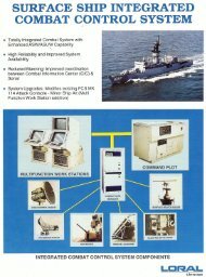
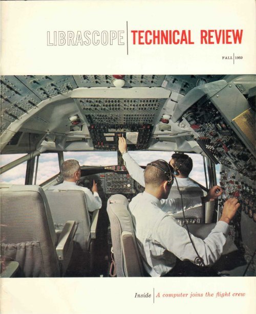
ON THE COVER.. .Boeing's 707 jet passenger transport is typical of the<br />
modern jet fleet now being introduced by world airlines. This exclusive<br />
color photograph shows a 707 cockpit during flight. At left is the<br />
captain, on the right, the first officer. The flight engineer is right, foreground.<br />
The empty chair at the left is for the 2nd officer (3rd pilot).<br />
The tiny ASN-24 electronic digital computer, described in the feature<br />
article on Page 4 , is an invaluable tool for navigation, especially on<br />
trans-polar and oceanic flights of this type of airplane.<br />
Photograph by <strong>Librascope</strong>, Inc., courtesy of American Airlines.
kay<br />
w«n. \«<br />
Ekmichan \<br />
.Chumtkan<br />
Alton*<br />
SHANTAR<br />
IS. i<br />
YNikotayevsk ,<br />
' ,<br />
.••Ayanij<br />
UstMayi<br />
<br />
%.<br />
T*ft«l*«<br />
.\otzetoue<br />
g f<br />
PT. BARROW<br />
? Barrow<br />
% • |<br />
%\)<br />
f- x \<br />
<br />
HtNRIETTA<br />
\ B e a tt f o r<br />
\<br />
«T, »cisii(i.ty<br />
o C a<br />
20,900 Ft 4. Nenana-» Fort Yukon > c PRINC<br />
''•• ' HtltSCHEU<br />
» Fairbanks , Mackenzie<br />
Bay<br />
» Anchorage<br />
RICHARD -^<br />
AMiWk/^ * "'.<br />
/ 4'-' Tuktud<br />
Gll/^ 'Cordova ,' ,* McPtwfwnl<br />
** u * * ,• / Dawson . j<br />
/' •• * £J Fort Good Hop<br />
Alaska Selkirk* _e ff"<br />
5.1 Cr«jf Bear Co p<br />
icean Sitka .'• /<br />
ALfXANDfi<br />
*»CHIC|LASd<br />
k, Normari<br />
Fort Sfnpsc<br />
I ' "*<br />
% ",.,..„ X-.»
1%" °1*u<br />
Gorkiy*<br />
Y«ssey<br />
Noriiifc?<br />
»«QBH*¥* i *'<br />
n Jf*j~* c<br />
Oudirtfca Ncnryy Port<br />
o<br />
yo
A Computer Joins the Flight Crew (continued)<br />
Weather dictates flight path.<br />
• Doppler radar furnishes ground<br />
speed and drift angle.<br />
• Cross wind drift causes Doppler<br />
frequency changes.<br />
• Doppler determined ground speed<br />
is fed to computer.<br />
5. Computer uses time delay<br />
information from LORAN to<br />
make position fix.<br />
6. Computer determines probable<br />
error in dead reckoning, and<br />
LORAN position fixes.<br />
1 • Computer applies credibility<br />
criteria and weighting function<br />
to LORAN fix to arrive at best<br />
estimate of position.<br />
is critically true in the case of the Navigator<br />
where each second lost in unnecessary<br />
deliberation means one-sixth of a<br />
mile difference between the actual position<br />
of the aircraft and the calculated<br />
position. With the extended ranges and<br />
increased fuel consumption of jet aircraft<br />
the smallest delays can seriously<br />
effect the economy and safety of the<br />
flight. These factors will assume even<br />
greater import as commercial aircraft<br />
speeds push beyond Mach 1.<br />
Radio ranges, LORAN, TACAN, doppler<br />
radar, celestial tracking devices, and<br />
gyro compasses have been developed to<br />
boost the speed and accuracy of aircraft<br />
navigation, but the final responsibility<br />
for interpreting data from these aids and<br />
the use of the information to keep the<br />
plane on course still rests with the Navigator.<br />
Also, while navigation aids can<br />
be relied on to provide the right information<br />
they do little to reduce the total<br />
number of computations required to<br />
solve navigation problems.<br />
The computer's role<br />
The role of the electronic digital computer<br />
as a member of the flight crew of<br />
modern airliners is that of assisting the<br />
Navigator in the performance of his
vital functions. With the computer doing<br />
time consuming routine work, the<br />
Navigator is freed to make decisions<br />
without distraction. He has time to keep<br />
up with navigation problems as speeds<br />
increase and tolerances decrease. And<br />
he can utilize a number of more sophisticated<br />
navigation techniques.<br />
At the crew briefing session, the Navigator<br />
receives the information from<br />
which he prepares his navigation flight<br />
plan. This information includes weather<br />
data, reporting points, ADIZ corridors,<br />
and alternate destination, which changes<br />
from flight to flight. The Navigator<br />
notes data needed by the computer.<br />
During the preflight check-out the<br />
Navigator feeds the data from the briefing<br />
into the computer. Already locked<br />
in the computer's memory are the equations<br />
it must use in making the navigation<br />
computations. It also stores tables<br />
of magnetic variation and deviation, for<br />
the entire Earth, as functions of aircraft<br />
position and heading, LORAN station coordinates,<br />
TACAN station positions, and<br />
the hour angle and declination of 57<br />
stars to be used in celestial navigation.<br />
As the Navigator feeds the new information<br />
into the computer, the computer<br />
itself is already sampling the various<br />
navigation aids and entering the data<br />
into the temporary storage portion of<br />
its memory. At the same time, it has begun<br />
the important self-checking of its<br />
myriad of logic circuits. Should any<br />
portion of the computer fail to respond<br />
correctly to the self-checking, the computer<br />
flashes a warning to alert the Navigator.<br />
The computer continues to check<br />
itself automatically throughout the flight.<br />
Passing over the marker beacon after<br />
take-off, the Navigator sets the computer<br />
to give him dead reckoning positions.<br />
In this mode of operation the<br />
computer samples true airspeed continuously<br />
and uses the data, together with<br />
compass readings and wind information,<br />
to compute ground speed and true course.<br />
The computer figures true ground<br />
speed and drift angle due to cross wind<br />
by using data from the Doppler radar.<br />
The Doppler radar transmits signals<br />
along four beams to the ground. The<br />
frequency of the signals reflected back<br />
to the radar vary in accordance to how<br />
rapidly the aircraft passes over the terrain.<br />
Drifting caused by cross winds<br />
causes frequency changes in the signals.<br />
The computer uses these changes to figure<br />
out the force of the cross wind and<br />
the drift angle.<br />
The drift angle and the true heading<br />
are combined to furnish the plane's true<br />
course. The ground speed is calculated<br />
and North and East velocity components<br />
are determined. These velocity components<br />
are integrated with respect to time<br />
to give the aircraft's position in latitude<br />
and longitude.<br />
The wind speed and direction determined<br />
by the computer are stored, and<br />
in case the Doppler signal fails, they<br />
are used to calculate the ground speed<br />
and course.<br />
The Navigator can examine the wind<br />
data at any time by querying the computer.<br />
Wind information is used by the<br />
Navigator for locating jet streams, comparing<br />
forecast with actual wind conditions,<br />
and for making wind reports.<br />
As a constant check on the dead<br />
reckoning calculations, the computer<br />
uses several radio navigation aids. Out<br />
over the middle of the Atlantic, LORAN<br />
is highly accurate and convenient to<br />
use. The positions of the LORAN stations<br />
to be used during the trans-Atlantic<br />
flight have been stored in the computer's<br />
memory and the Navigator can<br />
add the coordinates of additional stations<br />
at any time.<br />
LORAN fixes the aircraft's position by<br />
determining the time delay between the<br />
receipt of radio signals from two ground<br />
based stations. A hyperbola represents
the locii of all positions that would have<br />
the same time delay. Operation of LORAN<br />
requires that two pairs of stations be<br />
used. The time delay for the first pair<br />
of stations is measured and the hyperbola<br />
representing this time delay determined.<br />
The representative hyperbola<br />
for the second pair of stations is also<br />
determined. The intersection of the two<br />
hyperbolas is the position of the aircraft<br />
since it is the one position that satisfies<br />
the condition of being the point where<br />
the two measured time delays exist<br />
simultaneously. Previously the hyperbolas<br />
representing incremental time delays<br />
were drawn on a map of the flight<br />
area and the Navigator had to determine<br />
the two time delays and find the intersection<br />
of the particular hyperbolas.<br />
With the computer to aid him the Navigator<br />
only needs to take time delays<br />
from the Loran equipment and feed<br />
them to the computer. The computer<br />
solves the problem mathematically, using<br />
the basic equations for hyperbolas, and<br />
quickly presents the aircraft's position<br />
to the Navigator.<br />
When all these calculations were performed<br />
by the Navigator, he had to<br />
evaluate the possibility of errors in the<br />
readings; then decide between the accuracy<br />
of different positions given by alternate<br />
methods, such as dead reckoning<br />
and LORAN. The Navigator, from his experience<br />
with the accuracy of the navigation<br />
equipment and how it was working<br />
at the time, had to decide which position<br />
was right. Or he might have to make a<br />
compromise between the two to estimate<br />
the plane's true position.<br />
This whole process of deciding between<br />
different position fixes is now<br />
done by the computer. Each of the position<br />
fixes (one from dead reckoning<br />
navigation and the other from LORAN)<br />
has some expected error which is a<br />
function of the distance and direction<br />
traveled and other variables according<br />
to the principle of navigation involved.<br />
The computer considers the peculiarities<br />
of each navigation technique, figures<br />
out the probable error in each position<br />
and checks for gross errors. It finds<br />
gross errors by examining whether the<br />
positions fall within the allowable error<br />
(statistically this is the 2
the altitude and azimuth of the star are<br />
fed back to the computer.<br />
The star's altitude and azimuth are<br />
used by the computer to make another<br />
estimate of the aircraft's position which<br />
is checked against the positions fixed by<br />
the other navigation techniques. For further<br />
assurance of the position, the procedure<br />
can be repeated for another star.<br />
The possibility of bad weather and<br />
other emergency conditions makes it<br />
necessary for the Navigator to keep in<br />
mind alternate destinations. For this<br />
reason the computer stores the positions<br />
of the alternate landing spots and can<br />
furnish the Navigator with the course<br />
and distance to these points at any time.<br />
In the vicinity of Paris, the computer<br />
enters the final stages of the flight, continuing<br />
to monitor the position of the<br />
aircraft over France. Even as the airliner<br />
enters the landing pattern and<br />
starts its letdown, the computer is still<br />
watching the aircraft's exact position.<br />
The Doppler radar is still being monitored<br />
to determine wind speed and<br />
direction, in case weather conditions<br />
cause poor visibility. Like any other<br />
member of the flight crew, the computer<br />
stays at its job until the engines are<br />
silenced and the passengers begin to<br />
disembark.<br />
Speed plus accuracy<br />
In the six hours, or less, it takes to<br />
fly from Idlewild to Orly by jet, the<br />
computer will perform some 21,000,000<br />
computation steps. In each computation<br />
the computer continually monitors the<br />
aircraft's position and determines distance<br />
and bearing to flight check points<br />
and alternate destinations. A typical<br />
computation is completed by the computer<br />
in one second. This includes sampling<br />
the navigation aid used as source<br />
for the information, performing the<br />
arithmetical portions of the problem,<br />
and presenting the information to the<br />
Navigator. The computer performs these<br />
calculations with errors as little as one<br />
part in 32,000,000.<br />
By way of contrast, the same calculation<br />
would take several minutes of the<br />
Navigator's time and to match the computers'<br />
accuracy the Navigator would<br />
have to express his numerical data out<br />
to the sixth or seventh place. This is impossible<br />
on the basis of time alone.<br />
Using a slide rule, or even a desk calculator,<br />
the Navigator's probable error<br />
would exceed that of the computer by<br />
more than ten times.<br />
The general purpose character of the<br />
digital computer is of special significance<br />
for it provides the flexibility and<br />
versatility needed to keep up with projected<br />
advances in commercial aircraft<br />
performance as well as with new developments<br />
in radio and general navigation<br />
techniques. All that is required to make<br />
the computer compatible with improvements<br />
or new developments is a change<br />
in the computer program directing it to<br />
perform the new computations needed<br />
to utilize the latest equipment and methods.<br />
The computer circuitry and elements<br />
remain unchanged. No one can<br />
appreciate the computer's speed, accuracy,<br />
and flexibility, more than the Navigator<br />
himself.<br />
The ASN-24<br />
The computer on this trans-Atlantic<br />
flight is no science fiction dream. It exists<br />
today and has been flying for morei<br />
than a year. Designated the AN/ASN-J<br />
24, the electronic digital navigation computer<br />
is the result of a development<br />
program co-sponsored by <strong>Librascope</strong>,<br />
Incorporated, and the Air Force.<br />
Weighing only 31 pounds, the ASN-<br />
24 easily wins the title as the world's<br />
smallest general purpose digital computer.<br />
Volume is a mere 0.6 cubic feet.<br />
The ASN-24 employs "general purpose"<br />
computing techniques which permit<br />
changing its computing functions<br />
simply by changing the internally stored<br />
program. The computer uses a magnetic<br />
storage drum memory, and employs<br />
only silicon junction circuits. Already<br />
life tested at 110° C for over 16,000<br />
hours, the computer is highly reliable<br />
and has a mean free time to failure of<br />
over 500 hours.<br />
As navigation aids become more sophisticated,<br />
the ASN-24 will be able to<br />
provide even more rapid and accurate<br />
calculations. The computer, as a member<br />
of the flight crew, brings airline<br />
flight even nearer to achieving clearly<br />
marked highways in the sky.<br />
A. KERECHUK
COMPUTERIZING THE PROCESS INDUSTRY
Colorado utility uses LIBRATROL-500 for increased efficiency and profits<br />
1Processing requirements have become<br />
so complex and precise in many industries<br />
that the human operator no longer<br />
can produce the results dictated by quality<br />
standards and operating economies.<br />
As a result, a swing to automatic<br />
process control is developing as the<br />
processors seek new ways to improve<br />
quality and increase production while<br />
reducing costs.<br />
One concept that is attracting increasing<br />
attention from process industry<br />
managements is that of "computerized"<br />
process control. The LiBRATROL-500 industrial<br />
process control system, built by<br />
<strong>Librascope</strong>, Inc. and marketed by GPE<br />
Controls, Inc., embodies this concept.<br />
The LiBRATROL-500 is designed for all<br />
three of the presently used computer<br />
control techniques: monitoring, computer-direction,<br />
and automatic closed<br />
loop control. In its basic mode, the<br />
LiBRATROL-500 monitors the processing<br />
operation. It compiles the various data<br />
from transducers, performs the required<br />
computations and presents the information<br />
to the process operator who then<br />
takes appropriate action. Specific data<br />
for management and accounting use are<br />
also tabulated.<br />
The first computerized system ever<br />
used in on-line gas dispatching control<br />
utilizes the LiBRATROL-500 in this basic<br />
monitoring mode. The system will monitor<br />
gas flow meters at purchase points<br />
throughout the greater Denver area and<br />
the State of Colorado for the Public<br />
Service Company of Colorado and its<br />
subsidiaries.<br />
It will compute the total hourly and<br />
accumulated demand for each hour of<br />
the day. The utility company is charged<br />
for gas on the basis of a fixed commodity<br />
charge, combined with a demand<br />
charge based on the highest daily peak<br />
demand recorded during a 12-month<br />
period. The computer information from<br />
the LiBRATROL-500 system will be used<br />
by the Gas Load Dispatcher to control<br />
these peaks to avoid higher demand<br />
charges than are absolutely necessary<br />
to serve the utility's requirements.<br />
In addition to this on-line duty in the<br />
dispatching center, the computerized<br />
system will provide additional engineering<br />
calculations for other divisions of<br />
the Public Service Company.<br />
Establishing supply charges<br />
The cost of gas to the Public Service<br />
Company of Colorado is computed on<br />
a two-part rate. The two portions of the<br />
rate are the commodity component and<br />
the demand component. Each and every<br />
cubic foot of gas carries the commodity<br />
rate. The demand component is based<br />
on the peak demand established during<br />
any one day in a year and is then applied<br />
over the next eleven months.<br />
If a higher peak demand is recorded<br />
during the next eleven-month period, the<br />
demand component is revised upwards to<br />
account for this increased peak demand.<br />
This revision would increase the charges<br />
to the utility over the following eleven<br />
months, or until a higher peak demand<br />
was recorded.<br />
As operating expenses are adversely<br />
affected by increased demand charges,<br />
it is necessary to insure control of the<br />
peak usage within the gas system. The<br />
Public Service Company monitors their<br />
demand on a twenty-four hour basis<br />
throughout the year. Adjustments are<br />
made by interrupting service to certain<br />
industrial customers. To obtain preferential<br />
rates, these industrial customers<br />
must agree to curtail use if the demand<br />
to the area approaches the condition of<br />
exceeding the pre-established peak usage.<br />
The Gas Load Dispatcher must monitor<br />
the hour-by-hour demand, anticipate<br />
unusual demand due to weather<br />
conditions, and evaluate the hourly load<br />
increase in terms of necessary industrial<br />
curtailment. By monitoring the static<br />
pressure, temperature, and differential<br />
pressure data telemetered in from the various<br />
purchase points in the gas system,<br />
the Dispatcher is able to compute the<br />
flow at each point and add these to<br />
determine the total system demand.<br />
At the present time, the utility requires<br />
the monitoring of 44 different<br />
telemeters. The instruments from which<br />
the Dispatcher determines the flow at<br />
each point must be read hourly and the<br />
value of the flow computed. The number<br />
and complexity of the calculations<br />
involved consumes from 30 to 45 minutes<br />
of each hour's time. This is an extreme<br />
burden upon the dispatcher, who<br />
must also devote a large portion of his<br />
time to making decisions which will<br />
control the demand and maintain adequate<br />
gas supplies in the several systems<br />
under his supervision.<br />
Computerized process control<br />
In optimizing process control, the key<br />
to success is matching data processing<br />
with the time-control requirements. Vast<br />
amounts of data, which reflect variations<br />
in the process, must be collected, analyzed<br />
and displayed to permit control<br />
decisions to be made in time to effect<br />
corrective and optimizing action.<br />
When large numbers of variables with<br />
rapidly changing values are involved,<br />
the factor of time is especially important.<br />
Time lost in the preparation of<br />
data suitable for making decisions results<br />
in possible losses in quality, reliability,<br />
efficiency and safety.<br />
The primary advantage of computerized<br />
process control is that it permits<br />
control decisions to be made at rates<br />
which match the time constants of the<br />
process and system involved. Since these<br />
time factors vary from process to process,<br />
and each process control situation<br />
requires control elements custom tailored<br />
to particular specifications, the<br />
LiBRATROL-500 system was developed to<br />
cope with the large number of variables<br />
and rapid computation common to the<br />
majority of process problems.<br />
In assisting the Gas Load Dispatcher,<br />
the computerized system assumes the<br />
responsibility for monitoring the flow<br />
information, performs the calculations,<br />
and presents the demand data to the
On-line and offsystem<br />
in Public Service<br />
'ine operations of LIBRATROL -500<br />
company.<br />
— OFF LINE—<br />
GAS<br />
MEASUREMENT<br />
! 1<br />
GAS<br />
MEASUREMENT<br />
POO I<br />
TECHNICIANS<br />
,<br />
7<br />
GAS SUPPLY<br />
ENGINEERING ;] ENGINEERING<br />
DEPARTMENT j '_ DEPARTMENT<br />
;<br />
1<br />
GAS<br />
DISPATCHING<br />
I<br />
1<br />
DISTRIBUTION<br />
VICE PRESIDENT<br />
GAS OPERATIONS<br />
1<br />
ENGINEERING<br />
"r<br />
ENGINEERING<br />
DEPARTMENT<br />
1<br />
TECHN.C.ANS<br />
' m<br />
GAS<br />
DISTRIBUTION<br />
OFF LINE<br />
1<br />
CLERICAL<br />
POOL<br />
O<br />
"B<br />
r<br />
. m<br />
— LIBRATROL-! 500 COMPUTERIZED SYSTEM<br />
|<br />
Dispatcher. This permits the Dispatcher<br />
to devote the major portion of each<br />
hour to the critical decisions affecting<br />
proper study and distribution of the gas.<br />
The flow data for the computer is<br />
provided from circular chart recorders.<br />
Each recorder is fitted with a retransmitting<br />
potentiometer which generates<br />
an output voltage proportional to the<br />
value of the flow parameter being monitored<br />
by the recorder.<br />
The potentiometer output feeds to a<br />
voltage-to-digital converter of the successive<br />
approximation type. The converter<br />
translates the input voltages into<br />
digital signals which feed directly to the<br />
computer. The time to convert the voltage<br />
from the retransmitting potentiometer<br />
into digital signals representative of<br />
the data value is only one millisecond.<br />
The digitizing process is initiated on<br />
command from the computer.<br />
Computing demand data<br />
A 72-channel commutator permits the<br />
computer to obtain data from any of<br />
the data sources on command. The 72<br />
data sources consist of 55 retransmitting<br />
potentiometers, which provide static<br />
pressure, differential pressure and temperature<br />
data from the recorders. There<br />
are also twelve retransmitting potentiometers<br />
providing data from the telemetry<br />
system which monitors the<br />
Western Slope Gas District, and two<br />
channels which indicate that parallel runs<br />
at a given meter station are in operation.<br />
There are three spare channels for future<br />
metering operations.<br />
During the sixth minute of each six<br />
minute interval in an hour, the computer<br />
samples each of the data sources for the<br />
differential and static pressures recorded<br />
at the flow meter. The square roots of<br />
the two pressure measurements are determined<br />
and stored. These values are<br />
used to form the square root factor of<br />
the flow equation. At the end of each<br />
hour period, the computer averages the<br />
square root values for each flow meter<br />
and checks the flow temperature. The<br />
averaged square root values and the temperature<br />
are used in the computation of<br />
the flow during that hour. In addition, at<br />
the end of each hour, the hourly flow and<br />
accumulated flow is presented to the Dispatcher.<br />
The flow accumulation cycle is<br />
repeated every 24 hours.<br />
Basic to the calculation of the flow is<br />
the orifice factor which defines the relationship<br />
between the pressure measurements<br />
and the flow on the basis of the<br />
characteristics of the gas, of the flow<br />
meter, and the flow itself. The computer<br />
determines the value of this factor in<br />
accordance with the "Gas Measurement<br />
Committee Report Number 3" of the<br />
American Gas Association.<br />
This formula for the calculation of gas<br />
flow from orifice meter measurements is:<br />
Qi, = C'V n wPf<br />
where:<br />
Q h = quantity rate of flow at base<br />
conditions, ft 3 /hr<br />
C' = orifice flow constant<br />
h w = differential pressure in inches<br />
of water at 60° F.<br />
p f = absolute static pressure in psi.<br />
This equation is solved by the computer<br />
each hour for each of the metering<br />
points. The values of differential pressures<br />
and static pressures are telemetered<br />
from the orifice meters at the purchase<br />
points. The square roots of the differential<br />
pressure and the absolute static pressure<br />
are determined by the computer
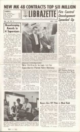
ORIFICE CONSTANT<br />
MULTIPLYING FACTORS<br />
PROGRAMMED SELECTION<br />
O<br />
—•-<br />
" 72-CHANNEL RELAY<br />
COMMUTATOR<br />
AGE DIGITIZER<br />
DIGITAL CLOCK<br />
INPUT/OUTPUT LOGIC AND<br />
ARITHMETIC AND CONTROL<br />
CIRCUITS<br />
VJII<br />
FLEXOWRITER<br />
INPUT POTENTIOMETERS FOR STATIC PRESSURE,<br />
DIFFERENTIAL PRESSURE, AND TEMPERATURE<br />
MEASUREMENTS<br />
4096-WORD MAIN MEMORY<br />
LIBRATROL-500 Computerized Process Control System<br />
For On-Line Gas Dispatching Control<br />
for each metering point every six minutes<br />
and the average of the values over an<br />
hour period is used to compute the flow.<br />
The orifice flow constant, C', is defined<br />
as the rate of flow in cubic feet<br />
per hour under base conditions when the<br />
^/h w p ( equals one. The orifice flow constant<br />
is a function on some nine flow and<br />
orifice parameters, all of which must be<br />
considered in computing the values of<br />
the constant.<br />
The nine parameters affecting the<br />
value of the orifice flow constant are<br />
basic orifice factor, Reynolds number,<br />
expansion factor, pressure base, temperature<br />
base, flowing temperature, specific<br />
gravity, super-compressibility, and manometer<br />
factor.<br />
These factors influence the value of<br />
the constant in rather complex ways and<br />
the computer has been programmed to<br />
compute the effects of the factors and<br />
the final value of the constant.<br />
"Doubles in brass"<br />
The extreme speed at which the computer<br />
can complete the monitoring and<br />
calculations involved in determining the<br />
demand leaves it with approximately five<br />
minutes out of every six free to accomplish<br />
additional computing tasks. To take<br />
full advantage of this, the utility is programming<br />
the computer to carry out<br />
the prime objective of demand calculations,<br />
and in addition, perform valuable<br />
engineering calculations for several other<br />
divisions of the Public Service Company.<br />
A "time box" program has been established<br />
to set up a priority sequence<br />
of programs for the computer to follow.<br />
This program makes it possible for the<br />
computer to perform the monitoring and<br />
calculation during each sixth minute and<br />
again at the end of the hour. It then<br />
takes up additional computational work<br />
in the vacant five minutes between sampling<br />
periods.<br />
One of the most important engineering<br />
problems which the computer aids<br />
in solving is the analysis and design of<br />
the gas distribution system. The multitude<br />
of various main sizes, which carry<br />
the gas to all points of the system, present<br />
a maze of paths, intersections and<br />
return paths which must be continuously<br />
analyzed to determine the effects of new<br />
service areas and new supply points on<br />
pressure and demand.<br />
A mathematical technique called the<br />
Hardy Cross method formerly enabled<br />
the distribution engineers to analyze the<br />
overall system, but the method required<br />
a tremendous number of trial and error<br />
cycles of computations. On a time basis<br />
alone, the performance of these computations<br />
by the human dispatcher was<br />
virtually impossible.<br />
While the computer cannot display<br />
the originality or creativity of its human<br />
operators, it does excel in the area of<br />
rapid and accurate calculation. For this<br />
reason the Hardy Cross technique is<br />
used quite successfully in the computer.<br />
Rapid and accurate analysis of the distribution<br />
system performance aids the<br />
Denver area by providing increased and<br />
more reliable gas service.<br />
Ability to "grow" with demand<br />
One of the big advantages of the<br />
LiBRATROL-500 system is that management<br />
may install the equipment at early<br />
and less sophisticated stages of process<br />
plant development, and utilize the results<br />
to install more fully automatic control<br />
as the process requirements are evaluated.<br />
In many cases, such a system could<br />
be utilized to monitor pilot and short<br />
runs to establish basic operating criteria.<br />
The system is used by the Public<br />
Service Company for the basic mode of<br />
monitoring and calculating. It may also<br />
be used for the more sophisticated computer-directed<br />
control. In that mode, the<br />
system is used to calculate, on the basis<br />
of data monitored by the instrumentation<br />
and information stored in the computer,<br />
what the optimum set-points in the<br />
process should be to realize maximum<br />
efficiency, maximum output, or to reach<br />
a desired condition in minimum time.<br />
This information is presented to the operator<br />
to permit him to alter the controls<br />
manually to meet the conditions directed<br />
by the computer.<br />
In processes where the relationship<br />
between the primary and secondary<br />
effects of control variations are understood,<br />
the LiBRATROL-500 system is used<br />
in full automatic eontrol o'f the process.<br />
With the control loop closed through<br />
the computer, automatic trimming operations<br />
are carried out by monitoring<br />
set-points and changing them as required.<br />
The LiBRATROL-500 computerized<br />
process control system incorporates a<br />
high-speed digital computer which was<br />
designed to handle three factors: a large<br />
number of variables, the requirement for<br />
intermittent information storage, and the<br />
rapid computation of process problems.<br />
Backing up the computer is a wide<br />
range of input-output equipment which<br />
creates a logical controls system without<br />
excessive instrumentation. The control<br />
system is especially suitable for use in<br />
petroleum and chemical industries, gas<br />
and electric utility plants, in steel mills<br />
and the aircraft industry. A new, and<br />
growing, use is in atomic energy plants<br />
where remote control is a necessity.
0<br />
Q.<br />
E<br />
o<br />
O<br />
-' /<br />
\<br />
ill
The LGP-SO is manufactured for<br />
the Royal Precision Corporation by<br />
<strong>Librascope</strong>, Incorporated. It is sold<br />
and serviced by Royal McBee Corporation.<br />
Royal Precision Corporation is<br />
jointly owned by Royal McBee Corporation<br />
and General Precision<br />
Equipment Corporation.<br />
-Planned Vacationland<br />
ACROSS THE BARREN, sunbaked slopes<br />
at the edge of an inland sea, a caravan<br />
of trucks fanned out to predetermined<br />
positions. Surveyors, stakemen, graders<br />
and construction crews started work in<br />
the midst of orderly confusion.<br />
Slowly from the rock punctuated<br />
landscape, a pattern of roads, utility<br />
lines and residential lots began to take<br />
shape. More than 20,000 acres began the<br />
almost overnight transformation from<br />
wasteland into an all-year residential<br />
and vacation resort.<br />
The surveying crews, staking out the<br />
first units of 50,000 lots at California's<br />
immense Salton Sea project, were working<br />
from data supplied by a computer,<br />
172 miles away in Los Angeles. The entire<br />
new California resort subdivision,<br />
including marinas, luxurious hotel and<br />
motel areas, bustling shopping centers<br />
and varied recreational facilities, has<br />
been computer planned and directed.<br />
The Salton Sea project is the culmination<br />
of a cooperative effort of major<br />
Southern California real estate developers.<br />
Ten years will be required before<br />
construction is completed on the last<br />
building of the self-contained city located<br />
at the edge of one of America's<br />
only two inland salt water lakes.<br />
At Treadwell Engineering Co., in<br />
Arcadia, at the edge of the sprawling<br />
greater Los Angeles metropolitan area,<br />
a <strong>Librascope</strong>-developed LGP-30 computer<br />
is daily performing the computations<br />
that would ordinarily require<br />
hundreds of engineering manhours to<br />
complete.<br />
Awarded the contract for planning<br />
the giant subdivision, Treadwell was<br />
called upon to produce huge quantities<br />
of survey maps, grading and construction<br />
plans, and legal real estate descriptions.<br />
Vernon Jones, vice president in<br />
charge of Treadwell's electronic computer<br />
division, estimates that to turn<br />
these out manually would be almost<br />
impossible, especially with today's shortage<br />
of qualified engineers.<br />
Treadwell must compute the area of<br />
each new tract in the subdivision and<br />
determine the most desirable size of<br />
individual residential and commercial<br />
lots. The Salton Sea project is a complete<br />
city, with industrial areas as well<br />
as business centers, schools and shopping<br />
areas conveniently planned for<br />
central access.<br />
To make the most efficient use of the<br />
land, the computer adjusts lot boundaries<br />
and sizes to fit the master plan.<br />
After deciding how large each lot will<br />
be, the computer then insures that all<br />
survey markings agree with the government<br />
bench marks or monuments, the<br />
master references which dot the country.<br />
Grading and construction plans are<br />
prepared by the computer from the designer's<br />
drawings. An important consideration<br />
is drainage. Even desert land is<br />
subject to short but heavy downpours<br />
that must be drained away without<br />
muddy pools or erosion.<br />
Finally, county authorities require<br />
subdivision maps and legal descriptions<br />
for each tract. All of this computation<br />
is performed by a desk-sized LGP-30<br />
general purpose digital computer.<br />
The big advantage of using a computer<br />
for the engineering problems involved<br />
in subdividing such a large tract<br />
is first of all a savings in time. In dividing<br />
up a tract into 5,500 lots, for example,<br />
over 30 engineers would have been<br />
required to perform the computations.<br />
In the same time, 5 engineers and the<br />
LPG-30 did the same job—without the<br />
necessity for extra supervisory time to<br />
check for ordinary mathematical errors.<br />
Treadwell switched over from manual<br />
solution of engineering problems to the<br />
computer operation in a few days. Information<br />
required by the computer is<br />
exactly the same that an engineer would<br />
need. The only special training for the<br />
engineers who work with-the computer<br />
was a short instruction on punching<br />
tape for the computer. An LGP-30 uses<br />
punched tape for its instructions, although<br />
it typewrites the solutions.<br />
Each engineer has his own tape typewriter<br />
right at his desk. As he figures<br />
out the physical dimensions he punches<br />
them onto the tape. Most of the engineers<br />
are so skilled at this now that they<br />
can prepare the punched tape as rapidly<br />
as they formerly prepared worksheets<br />
for manual computation. When the tape<br />
is finished, it is taken to the LGP-30.<br />
As the tape is fed into the computer,<br />
all the mathematical operations are performed<br />
by the machine. Once all of the<br />
data is in the computer, it calculates the<br />
unknown values and prints the correct<br />
solution on an output form, or tape. The<br />
computer can be programmed to give<br />
the answer in columns, lines, or to fill<br />
certain blanks in a form.<br />
Calculations handled with ease<br />
The computation of lot traverses is<br />
one of the most demanding engineering<br />
problems in subdivision layout. It requires<br />
the highest degree of skill and<br />
the most time. Using the LGP-30 to<br />
solve traverse unknowns has reduced the<br />
time and eliminated the inevitable risk<br />
of human errors in calculation.<br />
Treadwell is computing a number of<br />
different traverse problems for the Salton<br />
Sea project. Some require calculation<br />
of the length and bearing of an<br />
unknown side of a lot; others require<br />
finding two lengths when all bearings<br />
are known; or finding two bearings<br />
when all the lengths are known. Other<br />
problems solved by the computer are<br />
finding the length of one course and the
Computer-Planned Vacationland<br />
(continued)<br />
bearing of another. Error of closure<br />
(EOC) of a closed traverse, or the area<br />
of a lot must be calculated in many<br />
cases. All of these problems required<br />
many hours of painstaking hand figuring,<br />
then hours of patient checking to<br />
be sure there were no calculation errors.<br />
The only hand operation needed in<br />
the figuring of traverse problems with<br />
the LGP-30 is the transfer of actual<br />
Programmers translate information<br />
from drawings to tape for computer<br />
physical dimensions from a map to a<br />
tape. Where engineers once had to<br />
spend a lot of time looking up angular<br />
function values, working manual calculators<br />
and recording the results on special<br />
worksheets, the LGP-30 now does<br />
the entire job, and in only a fraction of<br />
the time.<br />
In a typical problem at Salton Sea,<br />
the engineer starts out with a map of<br />
the area on which are recorded the<br />
measurements made by a surveying<br />
team. This includes data on the number<br />
of sides of the lot, the direction, bearing<br />
Treadwell's Vernon Jones checks results<br />
typed out by the LGP-30<br />
and length of each side.<br />
The engineer types these out on his<br />
tape typewriter, which punches the symbols<br />
onto the paper tape in a language<br />
the computer can understand. He uses<br />
the same accuracy that was formerly<br />
required for hand calculations. Angles<br />
are recorded to the nearest second, and<br />
length is put down to the nearest hundredth<br />
of a foot. At the end of each<br />
complete problem instruction, he types<br />
a stop code which instructs the computer<br />
to hold the answer for use in a<br />
subsequent problem.<br />
The typewriter produces both a typewritten<br />
page and the punched tape. The<br />
punched tape not only feeds the problems<br />
into the computer, but may also<br />
be filed for recalculation of the same<br />
problem at any later time.<br />
The computer then computes all of<br />
the answers, and retypes the information<br />
on the original sheet, under the data<br />
which was typed while preparing the<br />
punched tape. This gives problem and<br />
answer on the same page and permits<br />
instant cross checking of the results.<br />
Area can also be computed on a traverse,<br />
and this is usually given to the<br />
nearest hundredth of an acre for plots<br />
larger than one acre, and are given to<br />
the nearest tenth of a square foot for<br />
plots smaller than an acre.<br />
Treadwell has programmed the LGP-<br />
30 to give answers to problems concerning<br />
traverses with as many as 64
sides. This number is sufficient for the<br />
largest and most complex tract found in<br />
subdivision work. With this type of program,<br />
Treadwell engineers may work<br />
with side lengths up to 8,192 feet and<br />
side bearings up to 90 degrees.<br />
In one problem recently the time<br />
taken to prepare a punched tape for the<br />
LGP-30 was about five minutes. It then<br />
took about two minutes to feed the tape<br />
through the computer, and for it to complete<br />
its calculations, including printing<br />
the output. Although this is only seven<br />
minutes from the beginning of the problem<br />
to the printed solution, former hand<br />
methods by a skilled engineer would<br />
take about an hour, and still require<br />
additional supervisory time for checking<br />
the hand-calculated figures.<br />
One of the biggest advantages has<br />
been the increase in accuracy of all<br />
solutions. By reducing the number of<br />
errors, the time required for rechecking<br />
the computer's figures has been reduced<br />
to almost nothing. The only check required<br />
is to be sure the taped instruction<br />
data to the machine has been prepared<br />
correctly.<br />
Jones noted that morale in the Engineering<br />
Department has risen to a new<br />
high since the computer was installed.<br />
During rush jobs, engineers formerly<br />
had to work nights and weekends to<br />
finish mountains of calculations in time<br />
for engineering deadlines. Use of the<br />
LGP-30 has eliminated this by permitting<br />
more efficient scheduling, and by<br />
transferring the bulk of calculation time<br />
to the computer itself.<br />
A major benefit to the company has<br />
been the ability to use a smaller staff of<br />
engineers more effectively. This small<br />
staff of highly skilled engineers utilizes<br />
the work capacity of a group of draftsmen<br />
that formerly required almost double<br />
the number of engineers feeding in<br />
data from which to prepare drawings<br />
and maps. The number of errors which<br />
were formerly encountered between the<br />
designers and the final maps have been<br />
cut to almost nothing.<br />
The LGP-30<br />
As these maps are finished at the<br />
Treadwell offices in Arcadia, they are<br />
sped by messenger to the construction<br />
site on the edge of the Salton Sea. Here,<br />
graders and construction men turn the<br />
maps and plans into reality—a modern<br />
new all-year resort city on the edge of<br />
an inland sea, teeming with sport fish<br />
and providing year-round recreation—<br />
the city planned by a computer.
A new technique of digital data recording,<br />
for use in performance evaluation<br />
of complex analog computing and<br />
control systems, records data directly<br />
from analog devices within the system.<br />
Developed by <strong>Librascope</strong>, Incorporated,<br />
for acquisition of performance data during<br />
simulated "trial runs" of various<br />
analog systems built by the company,<br />
the technique involves recording the<br />
condition of a large number of variables<br />
in near simultaneous reference.<br />
The analog system being considered<br />
here will generate a staggering amount<br />
of data during relatively short (20-30<br />
minute) operating periods. A detailed<br />
evaluation of the data must then be made<br />
to determine the system's performance<br />
characteristics accurately.<br />
A number of different approaches<br />
have been taken in collecting analog information<br />
for evaluation. Pen recorders<br />
and similar devices can be used to provide<br />
continuous records of the different<br />
variables within the system. However,<br />
arithmetical processing of the data is<br />
required for complete evaluation of the<br />
performance in respect to time, making<br />
the extraction of data from oscillograph<br />
records impractical for complex systems.<br />
The most desirable technique for obtaining<br />
the information needed to assess<br />
performance is to convert analog signals<br />
directly to digital form, and to record,<br />
in virtually simultaneous reference, the<br />
digital data for the requisite number of<br />
variables. The recorded digital information<br />
can then be fed into a general purpose<br />
computer for rapid evaluation.<br />
Such a recording technique, capable<br />
of monitoring up to 100 variables, has<br />
been developed by <strong>Librascope</strong>, Inc.<br />
Data recording can be accomplished<br />
within a fraction of a millisecond. When<br />
considered with respect to the speeds at<br />
which the variables undergo change, the<br />
event and its recording are, for practical<br />
purposes, simultaneous.<br />
To provide a finite number of discrete<br />
DIGITAL<br />
EVALUATION<br />
OF ANALOG<br />
SYSTEMS<br />
data recordings, a sampling rate is establishing<br />
which will provide close tracking<br />
of the control system being monitored.<br />
The analog variables are converted to<br />
digital form by positioning binary-coded<br />
decimal shaft converters. A scan matrix<br />
is programmed to sample the data at<br />
the specified times and store it temporarily<br />
on a magnetic drum. The data is<br />
maintained in this buffer memory until<br />
readout circuits feed it to a high-speed<br />
tape punch. After the trial run is completed,<br />
the paper tape data may be converted<br />
to printed form by an electric<br />
typewriter, or may be used to prepare<br />
punched cards or magnetic tapes.<br />
The technique is suitable for use with<br />
analog computers, and with analog control<br />
systems such as those used in missile<br />
control and guidance, flight simulation,<br />
autopilots, and in process control for<br />
the chemical, petroleum and petrochemical<br />
industries. Digital data recording<br />
has been used at <strong>Librascope</strong> as a method<br />
of gathering development information<br />
on new analog systems prior to finalizing<br />
designs for production.<br />
Fire control evaluation<br />
An excellent example of the potentials<br />
of such a recording technique exists<br />
in a special data recorder designed<br />
by <strong>Librascope</strong> to assess the performance<br />
of a U. S. Navy fire control system.<br />
In order to evaluate the fire control<br />
system, a printed record is made of 20<br />
analog variables at specified times during<br />
a trial run. Twelve of these variables<br />
are scanned and recorded at three-second<br />
intervals, and the remaining eight are<br />
recorded at the random occurrence of<br />
two events during the test.<br />
Twenty binary-coded decimal shaft<br />
encoders are used. A scan matrix samples<br />
the data from these at specified<br />
times. The data is then stored temporarily<br />
on a magnetic drum. Recirculating<br />
and readout circuits operate a high-speed<br />
paper tape punch to record the data
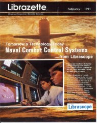
BIO<br />
\.\.\ \ F .//././<br />
\\\**///<br />
BIO<br />
///I<br />
// / M ZZZT<br />
B20 /<br />
B40 B100 B4D<br />
0 /<br />
B100<br />
Block diagram of system<br />
from the drum. Following the trial run<br />
the punched tape is fed through a tape<br />
reader and put into printed form by an<br />
electric typewriter.<br />
The twelve variables, monitored every<br />
three seconds, are scanned and recorded<br />
on the magnetic drum in approximately<br />
0.8 millisecond. This interval, considered<br />
in relation to the speed at which<br />
the variables undergo change, is essentially<br />
simultaneous.<br />
The analog variables are converted<br />
to a binary-coded decimal form for<br />
recording. This is accomplished with<br />
commutator-type, shaft-to-digital encoders.<br />
The values of 17 functions are<br />
transmitted by synchros, two are stepmotor<br />
functions and time is generated<br />
with a synchronous motor.<br />
Servos position both the analog-todigital<br />
encoders and display dials. A<br />
camera photographs the dials at the<br />
same instant that the converters are<br />
scanned electrically. The camera provides<br />
an alternate record in case of<br />
malfunction in the digital scan and<br />
memory unit during a test.<br />
To obtain the 17 synchro variables,<br />
the stator terminals of synchro generators<br />
in the fire control system are<br />
connected in parallel with the stator<br />
Memory drum turns at 3450 rj>m<br />
terminals of synchro control transformers<br />
in the recorder. The input signal<br />
to each servo amplifier is then taken<br />
from the rotor winding of the appropriate<br />
control transformer.<br />
The amplifiers may be used in either<br />
60-cycle or 400-cycle servo loops. Each<br />
amplifier has a crossover network for<br />
two-speed use. Each module of four<br />
amplifiers has its own separate, regulated<br />
power supply.<br />
Four amplifier modules are used for<br />
16 of the synchro signals. A special<br />
amplifier is used for the 17th, which is<br />
transmitted at 1100 cycles. This signal<br />
is demodulated and is converted to halfwave<br />
60-cycle pulses, phased with the<br />
1100-cycle signal.<br />
A disc-type shaft-to-digital encoder<br />
is used. The commutator-type disc consists<br />
of concentric rings which correspond<br />
to the weighted values of the<br />
brush locations. A binary-coded decimal<br />
(1-2-4-8) code is used. A two-brush<br />
pickoff system eliminates ambiguity.<br />
Each disc is divided into 200 divisions<br />
to produce coded numbers from 000<br />
to 199. Encoders with larger output<br />
ranges are used for the time conversion<br />
in the system.<br />
The encoder outputs are sampled by<br />
Commutator segment<br />
a high-speed scanning technique to provide<br />
parallel binary-coded decimal data.<br />
The scan and memory circuits are all<br />
packaged in the form of printed plug-in<br />
circuits. (Each circuit "card" is color<br />
coded for rapid identification.)<br />
Input sampling and selection of signals<br />
from each of the 20 encoders must<br />
be maintained in a predetermined sampling<br />
sequence. A program counter<br />
designates 44-word intervals through a<br />
circuit of six flip-flops.<br />
The scan and program counters operate<br />
continuously during a run. They are<br />
synchronized with the memory drum.<br />
Whenever a data sample is made, a<br />
record-recirculate flip-flop provides the<br />
time period required to locate the right<br />
data storage point in the memory.<br />
The magnetic memory drum has 1584<br />
engraved time points on the clock track.<br />
This is exactly six times the number of<br />
bits in the 44-word recirculation storage.<br />
Record and read heads on the<br />
four binary-coded decimal recirculation<br />
tracks are placed approximately 264<br />
time points (44 words) apart. This provides<br />
an operating frequency of about<br />
100 kilocycles. The access time to the<br />
number storage is about three milliseconds<br />
when the drum is driven by a
•Hi<br />
CONVERTED SCAN MATRIX BINARY-CODED,. RECORD AND<br />
AND • RECIRCULATE<br />
DECISION LOGIC DECIMAL DATAK CONTROL<br />
MAGNETIC<br />
DRUM MEMORY<br />
Scan and memory circuit diagram<br />
Readout section showing typewriter and tape punch equipment<br />
3450 rpm motor. This access time is<br />
only about 1/15 the cycle time of the<br />
paper tape punch, so no time is wasted<br />
in looking for new data to be punched.<br />
The tape punch operates at a speed of<br />
24 digits per second.<br />
The sampling control unit furnishes<br />
timing information for the recorder. A<br />
cam-microswitch is geared to the synchronous<br />
motor which drives the time<br />
converter. This circuit generates the<br />
three-second sampling command signals<br />
which are gated through the sampling<br />
control unit. Special circuits close relays<br />
in the unit to record the two random conditions<br />
which may occur.<br />
Three sampling flip-flops provide<br />
synchronization between the more or<br />
less random sampling and the "clocked"<br />
electronics in the memory unit.<br />
To get synchronization between the<br />
digital scan and memory section and the<br />
paper tape punch, an additional 44-<br />
word track is provided in the memory.<br />
This recirculation track is called the<br />
punch readout sync line. It provides one<br />
pulse positioned adjacent to each four<br />
binary-coded decimal digits punched by<br />
the tape punch. After each set of digits<br />
has been read into the tape punch, the<br />
pulse is stepped to the next set of digits.<br />
If the next digit location is blank, the<br />
pulse is stepped on until a location is<br />
found which does contain numerical<br />
data.<br />
In <strong>Librascope</strong>'s data recorder, it was<br />
decided to punch out only the continuous<br />
three-second samplings onto tape.<br />
Provisions were made to have the read-<br />
out sync pulse to step through only the<br />
continuous data section of the memory.<br />
At the end of the run, the pulse is<br />
stepped through all three data locations<br />
to clear the memory.<br />
A flip-flop circuit is provided to<br />
clear the readout sync channel and to<br />
locate a single pulse. This flip-flop is set<br />
high each time it receives an origin<br />
pulse. It remains high for one 44-word<br />
recirculation period, clearing the readout<br />
sync line and passing the single<br />
pulse in its proper location.<br />
The numerical data is recorded by<br />
the least significant digit first. But the<br />
tape punch punches out the most significant<br />
digit first. The sync pulse is<br />
synchronized with the most significant<br />
digit, and then steps back to the least<br />
significant. The pulse stepping is controlled<br />
at the rate of one digit per step.<br />
When it is in line with an unused digit, it<br />
automatically steps on so that when the<br />
punch is ready for new data, the sync<br />
pulse will be adjacent to this data.<br />
In order to print out on the electric<br />
typewriter, the punch tape must contain<br />
instructions for Tabulate and Carriage<br />
Return. This format control is normally<br />
used to print columns which will be<br />
easily read, with each containing successive<br />
values of a single analog variable.<br />
The control signal for Tabulate is<br />
placed after each recorded variable except<br />
at the end of each group of threesecond<br />
sampled data, where a signal for<br />
Carriage Return is placed. Such control<br />
signals are gated into storage flip-flops<br />
which correspond to the seven punch<br />
channels of the seven-hole paper tape<br />
used. Plate circuit relays are used to<br />
control the punch magnets according to<br />
the flip-flop storage.<br />
When the memory drum is cleared at<br />
the end of a run, the special data recorded<br />
at the times of random occurrences<br />
is read off from those portions of<br />
the memory space where it was retained,<br />
and this information is punched<br />
out last on the paper tape.<br />
The seven-hole paper tape is read by<br />
a motorized tape reader and the resulting<br />
coded signals are converted to sixhole<br />
typewriter code by a relay matrix<br />
in the encoder chassis. The output of<br />
the relay matrix then operates the electric<br />
typewriter. The motorized reader<br />
and the typewriter operate synchronously<br />
at ten digits per second.<br />
The readout arrangements are not<br />
limited to a single tape punch. As many<br />
as six punches may be operated simultaneously<br />
to permit more frequent data<br />
sampling, increased volume of data, or<br />
to allow making parallel recordings.<br />
Synchro amplifiers and mechanical<br />
follow-up sections may be eliminated<br />
where existing electro mechanical devices<br />
supply analog information. The analogto-digital<br />
converters can operate directly<br />
from any shaft. Inputs to the digital<br />
scan and memory sections may be originated<br />
by converters or from other digital<br />
devices.<br />
The output of the memory readout<br />
circuit can be recorded on magnetic<br />
tape or on punched cards as well as on<br />
punched paper tape.
MARKET RESEARCH<br />
to keep pace with<br />
A necessity<br />
customer needs<br />
A potential buyer of graphic recording<br />
equipment stood up in his office at a<br />
West Coast rocket engine facility, looked<br />
the visiting vendor in the eye and remarked,<br />
"Show me some equipment<br />
that's brand new from the bottom up.<br />
All you have here is a re-arrangement<br />
of circuitry encased in a two-tone<br />
painted frame. It won't do our job."<br />
This is the reception greeting some of<br />
the nation's electronic sales engineers<br />
who try to "sell an old dog in new<br />
sheep's clothing."<br />
Company policy which calls for modernization<br />
of existing equipment by<br />
merely modifying circuit design and<br />
mechanical structure leaves the firm's<br />
sales force literally "carrying the ball—<br />
to the competition's goal."<br />
Naturally this approach isn't working.<br />
Sales are diminishing, with the orders<br />
going to those firms who specialize in<br />
seeking out and answering customer requirements.<br />
Positive information must<br />
be obtained about improving the capabilities<br />
of a product.<br />
Aiding the engineering, sales and production<br />
force of any electronics company<br />
are marketing specialists who<br />
maintain constant surveillance on cus-<br />
tomer needs for a particular item. Time<br />
and expense must be invested in this<br />
procedure before a prototype unit can<br />
be designed. The competition dictates<br />
this principle.<br />
<strong>Librascope</strong>, a leader in the early development<br />
of plotters and graphic recording<br />
instruments, keeps up a continual<br />
evaluation of the company's entire product<br />
line. A new X-Y Plotter is being<br />
introduced after marketing research determined<br />
that former units would be<br />
outmoded by customer requirements in<br />
the near future.<br />
Particular procedures were adhered<br />
to before the new X-Y Plotter, Model<br />
210, could be developed. An engineering<br />
team from <strong>Librascope</strong> explored the<br />
present state-of-the-art and these evaluations<br />
were studied and projected into<br />
the future plotter design. The team investigated<br />
all instruments in the plottergraphic<br />
recorder market, noting advantages<br />
and disadvantages of each.<br />
Resulting information was considered<br />
by an outside market research group<br />
composed of sales engineers familiar<br />
with X-Y Plotter user requirements. A<br />
special questionnaire, to gain information<br />
directly from operators of plotters,<br />
was distributed for determination of<br />
user requirements.<br />
It was decided that a major operational<br />
feature would be a quick, accurate scale<br />
changing technique with scale expansion<br />
possible between each step. Push button<br />
scale switching with vernier control accomplished<br />
this.<br />
This technique enables the operator to<br />
fill the entire trace area with between<br />
scale voltage inputs. The servo control<br />
loop gain was designed to be independent<br />
of the scale changes, insuring no "jump"<br />
when scales are changed.<br />
High plotting output accuracy was<br />
stressed with a static accuracy of ±.1%<br />
of full scale, and a dynamic accuracy of<br />
±.2% of full scale at 10 inches per second<br />
tracing speed. Frequency response<br />
was designed to be flat to 0 — 1 cps<br />
±.2% of full scale at 6 inches displacement<br />
amplitude.<br />
A major complaint in the questionnaires<br />
regarding earlier plotters was the<br />
difficulty in inserting paper under the plotting<br />
arm. <strong>Librascope</strong> engineers solved<br />
this problem by supplying a push-button<br />
control which automatically retracts the<br />
arm from the paper and moves it completely<br />
off the plot area. Simultaneously,<br />
input signals are locked.<br />
A vacuum platen answers the problem<br />
of keeping the graph paper in place<br />
with positive hold down characteristics.<br />
The exterior configuration and accessibility<br />
of plotter operation was a main<br />
point of consideration and <strong>Librascope</strong><br />
engineers sought outside counsel from a<br />
top industrial designer. The result was<br />
a frame which met user requirements<br />
from such standpoints as human engineering<br />
and operational convenience.<br />
Latest state-of-the-art advances are<br />
incorporated in the <strong>Librascope</strong> X-Y<br />
Plotter, Model 210 — new from the<br />
ground up.<br />
QUESTIONN.<br />
NAME<br />
ADDRESS .<br />
POSITION<br />
COMPANY ADDRESS<br />
WHAT IS V~
"Progressive"<br />
quality control<br />
insures<br />
COMPUTER RELIABILITY<br />
RELIABILITY is one of the foremost considerations<br />
both in the design and the<br />
manufacture of electronic digital computers.<br />
Other considerations such as<br />
computer speed, accuracy and capacity<br />
lose much of their significance if the<br />
computer is subject to frequent operating<br />
failures.<br />
This requirement for maximum reliability<br />
has led <strong>Librascope</strong> to institute<br />
a program of "progressive" quality control<br />
aimed at eliminating defective assemblies<br />
at the point of origin. This<br />
progressive inspection process permits<br />
discovery of defects almost as they<br />
occur with a consequent saving of labor<br />
and materials which might otherwise<br />
have gone into a unit which would not<br />
pass final testing.<br />
Particular emphasis is placed on the<br />
quality control of the hundreds of<br />
etched circuit boards which make up<br />
the computer's complex electronic network.<br />
Relatively minor defects in the<br />
boards can result in intermittent or early<br />
operating failure after installation in the<br />
computer. With progressive inspection,<br />
these defects can be detected and the<br />
boards removed from the manufacturing<br />
process before additional time and materials<br />
are expended unnecessarily.<br />
This sequential quality control has<br />
speeded production, produced more reliable<br />
computers, and saved thousands<br />
of dollars in production costs.<br />
At <strong>Librascope</strong>'s modern Glendale facility,<br />
where over 50 types and models<br />
of computers are manufactured, highly<br />
complex etched circuit boards are assembled<br />
with as many as three hundred<br />
miniature components. The "wires" that<br />
connect components are flat metal ribbons<br />
formed by photography and chemical<br />
etch processing of a copper-clad<br />
plastic sandwich (an epoxy resin and<br />
woven glass fibre laminate).<br />
Many computer manufacturers purchase<br />
their boards from outside jobbers<br />
of etched circuit boards for subsequent<br />
component assembly. <strong>Librascope</strong>, however,<br />
in order to maintain high quality<br />
standards, purchases only the basic<br />
"sandwich" of copper-clad epoxy glass<br />
laminate. The manufacture of the etched<br />
circuit board is accomplished in <strong>Librascope</strong>'s<br />
own newly established production<br />
processing facilities.<br />
The manufacture of these is an excellent<br />
example of the progressive inspection<br />
sequence which has been instituted<br />
at <strong>Librascope</strong>. George Magurean, head<br />
of the Etched Wiring Processing Department,<br />
maintains a constant control<br />
of process conditions, as well as a<br />
progressive system of visual inspection<br />
of the boards as they proceed through<br />
their fabrication and assembly cycle.<br />
Preparing the board<br />
When the boards arrive at <strong>Librascope</strong>,<br />
they are visually inspected for<br />
general quality and possible shipping<br />
damage. Then they are cut to size and<br />
accurately punched in two places with<br />
location holes that remain in the board<br />
during the entire manufacturing process.<br />
Once the basic boards have been cut<br />
to size and punched, the protective vinyl<br />
coating applied over the copper surface<br />
is stripped away. The boards are cleaned<br />
chemically to remove all residuals and<br />
surface impurities. Next, the boards are<br />
air dried and vapor degreased. At this<br />
point, the boards are again inspected<br />
visually to assure they are ready for the<br />
next process.<br />
While awaiting further processing, the<br />
boards are cooled and stored in dustfree<br />
humidity-controlled cabinets. On<br />
removal from storage, the boards are<br />
dipped in a photo-sensitive emulsion<br />
resist which coats them with a film,<br />
much the same as in conventional photographic<br />
procedures. The boards are then<br />
air dried in their "storage" cabinets to<br />
a tack-free condition and inspected again<br />
to insure that the photo-sensitive emulsion<br />
resist coat was properly applied. At<br />
this point, the boards are baked in ovens<br />
to a maximum temperature of 160°F,<br />
and removed for storage in their dustproof,<br />
humidity-controlled cabinets until<br />
needed again.<br />
Photo processing<br />
To attain the highest standards of<br />
accuracy and quality in its etched circuitry,<br />
<strong>Librascope</strong> uses a recent development<br />
in photo-template masters. A<br />
translucent paper photoplate is glued to<br />
a transparent acrylic plastic. This construction<br />
insures that the dimensional<br />
characteristics of the paper template<br />
will be unaffected by changes in atmosphere<br />
and temperature. The plastic backing<br />
is equipped with two locating pins<br />
that precisely match the two location<br />
holes originally punched in the boards<br />
to guarantee accurate registration during<br />
photo processing and subsequent<br />
fabrication operations.<br />
The photo processing is semi-automatic.<br />
The photo-templates, together with the<br />
sensitized boards, are inserted into a<br />
vacuum frame, a timing clock is pre-set<br />
for just the right exposure selected for<br />
that particular application, and the<br />
vacuum frame with its contents is exposed<br />
to an actinic light source for the<br />
precise period of time required.<br />
When the boards have been developed,<br />
they are removed from the vacuum<br />
frame and subjected to vapor<br />
degreasing techniques which remove the<br />
photo resist coating from the unsensitized<br />
or unexposed areas. At the same<br />
time, the process hardens the exposed<br />
areas. The pattern developed on the<br />
boards at this point is not readily discernible,<br />
since the photo-resist coating
1 Printed circuit facility at <strong>Librascope</strong>,<br />
Incorporated, Glendale, California.<br />
2 Chemical and plastic formulations<br />
are continually checked for precise<br />
control.<br />
3 Each circuit board is painstakingly<br />
inspected and circuits are touched up.<br />
4 Careful visual inspection is made of<br />
each negative at each step of process.<br />
is somewhat transparent. To provide an<br />
easily distinguishable and visual control<br />
for subsequent operations, special dyeing<br />
techniques are employed to coat the<br />
photo printed areas with a black dye,<br />
leaving the copper-clad unprotected in<br />
the remaining areas. The dyeing technique<br />
reveals at this point whether any<br />
imperfections have occurred in printing<br />
and developing. If any have, they will<br />
be clearly visible to the eye.<br />
Solder plating<br />
Now the boards are ready for solder<br />
plating in electroplating tanks. The<br />
solder plating achieves two major objectives:<br />
It provides a durable etching<br />
resist necessary for developing the final<br />
circuitry pattern, and it facilitates subsequent<br />
dip soldering operations.<br />
By chemical procedures, the remaining<br />
photo emulsion resist is removed. At<br />
the same time the black dye comes off.<br />
After the solder plating operation, the<br />
boards are again closely observed by the<br />
operators to insure that the latest operation<br />
has resulted in no imperfections<br />
such as pin holes or misetched sections.<br />
Etching<br />
The boards are now ready for the<br />
etching process, which resembles chemical<br />
milling, or the preparation of engravings<br />
by a printer. Each board is<br />
mounted in a special fixture made of<br />
stainless steel and acrylic plastic. Both<br />
are resistant to the etching solution. The<br />
etching solution, a chromic-sulphuric<br />
acid, then eats away the copper portions<br />
of the board, while leaving the soldercoated<br />
parts untouched.<br />
Extreme care must be taken in the<br />
etching process to avoid undercutting<br />
the deposited solder material by overetching.<br />
This is achieved by precise<br />
control of the etching solution temperature<br />
and strength.<br />
After etching, the boards are washed<br />
in mechanical rinsers to free them from<br />
the solution. Again they are inspected<br />
by the operator, after which they are<br />
ready for the nickel-rhodium plating.<br />
Any area of the circuit boards that<br />
might be subjected to wear or abrasion<br />
such as the plug-in contacts is protected<br />
by plating with nickel-rhodium metal.<br />
This also minimizes corrosion.<br />
Finally, the boards are thoroughly<br />
scrubbed with a mild abrasive detergent<br />
to remove any foreign matter, finger<br />
grease, oil or other foreign deposits.<br />
Inspection in detail follows the scrubbing,<br />
and the boards are sent to the hole<br />
drilling and fabrication operation as final<br />
preparation for component assembly.<br />
The boards finally used in the many<br />
types and models of computers built by<br />
<strong>Librascope</strong>, may see service in general<br />
industry, in process control, in antisubmarine<br />
warfare, in photo-mapping,<br />
in navigating a jet, a missile or a space<br />
vehicle across the skies, or in any one<br />
of 50 different fields where <strong>Librascope</strong><br />
computers perform reliably.
TODAY'S ANTISUBMARINE<br />
WEAPONS CONTROL. COMPUTER<br />
THE TIME: Early 1940. THE ACHIEVEMENT: A small, compact ballistic computer<br />
for the U.S. Navy. THE RESULT: The beginning of <strong>Librascope</strong>'s leadership in<br />
the design, development, and production of weapons and navigation control<br />
systems and components.<br />
Today, <strong>Librascope</strong>-designed and manufactured electronic and mechanical<br />
equipment for the MK 113, MK 111, MK 110, MK 107, and MK 105 underwater<br />
fire control systems include computers, attack directors, torpedo and<br />
missile angle solvers, attack plotters, depth plotters, position keepers, target<br />
motion analyzers, stabilization computers, roll and pitch computers, and various<br />
indicators and control instruments. • <strong>Librascope</strong>'s simulation laboratories<br />
provide the Navy with a means for testing and analyzing the performance of<br />
equipment under "real attack" conditions. In the field, our engineers assist<br />
in the maintenance and improvement of <strong>Librascope</strong> systems.<br />
SHIPBOARD COMPUTERS<br />
For information on career opportunities at <strong>Librascope</strong>,<br />
write Glen Seltzer, Employment Manager.<br />
<strong>Librascope</strong>'s experience creating new concepts in computer<br />
—control systems for both military and industrial use can<br />
be accurately applied to your specific needs. • For detailed<br />
information and solutions to your computer problems, write.<br />
GENERAL<br />
PRECISION<br />
COMPANY