vtec air flow converterⅱ wiring diagram by model - APEXi USA
vtec air flow converterⅱ wiring diagram by model - APEXi USA
vtec air flow converterⅱ wiring diagram by model - APEXi USA

You also want an ePaper? Increase the reach of your titles
YUMPU automatically turns print PDFs into web optimized ePapers that Google loves.
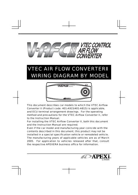
VTEC AIR FLOW CONVERTER<br />
WIRING DIAGRAM BY MODEL<br />
This document describes car <strong>model</strong>s to which the VTEC Air<strong>flow</strong><br />
Converter II (Product code: 401-A915/401-A815) is applicable,<br />
and ECU terminal arrangement drawings. For the operating<br />
method and precautions for the VTEC Air<strong>flow</strong> Converter II, refer<br />
to the Instruction Manual.<br />
For installing the VTEC Air<strong>flow</strong> Converter II, both this document<br />
and the Instruction Manual are required.<br />
Even if the car <strong>model</strong> and manufacturing year coincide with the<br />
contents described in this document, this product may not be<br />
installed in a special specification vehicle or re<strong>model</strong>ed vehicle.<br />
The manufacturing years of applicable vehicles are as of March<br />
2005. For application to vehicles released after that, consult<br />
the respective APEXERA business office for information.
Contents<br />
Introduction <br />
Precaution on Installation <br />
Installation <br />
ECU Arrangement Drawing <br />
How to Refer to the ECU Terminal Arrangement Drawing <br />
<br />
Table of Applicable Models <br />
ECU Terminal Arrangement Drawing <br />
Introduction<br />
“Safety precautions” are described in the Instruction Manual. Please read them before<br />
starting the installation work.<br />
“Signal words and their meanings” are described in the Instruction Manual for this product.<br />
The “Engine Control Unit” is abbreviated as “ECU” in this document. <br />
<br />
CAUTION<br />
Regarding the installation of this product, be sure that it is<br />
installed <strong>by</strong> an experienced professional.<br />
After completion of the installation, hand over this document, Instruction Manual, and<br />
Warranty to the customer (user).<br />
<br />
Do not pull the harness of the vehicle and the harness of this<br />
product, <br />
Wire breaking or a short circuit may occur, there<strong>by</strong> giving damage to this product and<br />
the vehicle.<br />
<br />
When removing or connecting a connector, be sure to unlock<br />
the locked (claw) status beforehand.<br />
When the connector is provided with a fixing bolt, loosen this<br />
bolt completely before pulling out the connector. <br />
The connector may be damaged.<br />
<br />
Arrange the harness of this product and the harness of the<br />
vehicle in portions that are not at a high temperature or are not<br />
movable. Arrange them so that water may not be splashed over<br />
them.<br />
Wire breaking or a short circuit may occur, there<strong>by</strong> giving damage to this product and<br />
the vehicle.<br />
<br />
Do not arrange the harness of this product and the harness of<br />
the vehicle near a sharp-edged material. Do not put the harness<br />
between materials <strong>by</strong> applying pressure to it.<br />
Wire breaking or a short circuit may occur, there<strong>by</strong> giving damage to this product and<br />
the vehicle.
Precaution on Installation<br />
When installing this product, do not use any electro-tap in any<br />
case.<br />
Using the electro-tap makes the contact status unstable. Its contact defect may causes<br />
a malfunction to the product and damage to this product and the vehicle.<br />
Be sure to use the attached splice and dedicated tools such as cutting pliers for electric<br />
work to install the product securely. <br />
<br />
Insulate the metallic portion of the harness securely with a<br />
vinyl tape.<br />
Caulking the plug<br />
<br />
<br />
<br />
<br />
<br />
<br />
<br />
<br />
<br />
Caulking the splice
The ground conductor of this product has two branches (black and brown).<br />
This has a very important significance to secure the voltage conversion<br />
accuracy. Connect the ground conductor <strong>by</strong> referring to the following figure.<br />
Installing the ground conductor in a different way from the connecting method<br />
specified <strong>by</strong> A’PEX will give damage to this product and the mounted car engine.<br />
Correct Connecting Method for the Ground Conductor <br />
Connect the ground conductor to two positions of the same line.<br />
Be sure to connect the brown wire to the ECU side.<br />
Allow a space of 1 cm or more between the connecting point of the black wire<br />
and the connecting point of the brown wire.<br />
Vehicle harness<br />
Engine<br />
Control Unit<br />
Brown wire (ground)<br />
Black wire(ground)<br />
Wrong Connecting Method for the Ground Conductor<br />
Vehicle harness<br />
Engine<br />
Control Unit<br />
Unite the ground<br />
wires into a single<br />
line.<br />
Brown wire (ground)<br />
Black wire(ground)<br />
Vehicle harness<br />
Engine<br />
Control Unit<br />
Do not connect the<br />
ground conductor<br />
to any position<br />
(e.g. chassis ground)<br />
other than the<br />
specified position.<br />
Brown wire (ground)<br />
Black wire(ground)<br />
The above figure explains only the connection of the ground conductor. For the<br />
other signal lines, refer to page 6 and page 7. Be sure to wire the power cable,<br />
ground conductor and other signal lines to the positions specified <strong>by</strong> A’PEX.
Installation<br />
Connecting the VAFC II<br />
.Remove the negative (-) terminal of the battery.<br />
<br />
There is some setting data on car audio, car navigation, etc. that is backed up <strong>by</strong> battery power<br />
supply. We recommend you to take a note of the data beforehand lest they should be lost.<br />
CAUTION<br />
Before starting the <strong>wiring</strong> work, remove the negative<br />
terminal of the battery.<br />
If not, a fire will be caused <strong>by</strong> short circuit, there<strong>by</strong> giving damage to electric parts.<br />
If the ECU connector is removed while the battery is connected, the engine<br />
warning lamp may light up continuously regardless of whether the VAFC II is<br />
installed or not. At this time, you must ask the distributor of each car <strong>model</strong> to<br />
perform maintenance and inspection.<br />
<br />
We shall not take all responsibility for damage of the<br />
vehicle or related devices that may be caused <strong>by</strong><br />
installation error.<br />
.Locate the Engine Control Unit (hereafter referred to as ECU) of the vehicle <strong>by</strong> referring<br />
to the Wiring Diagram <strong>by</strong> Model.<br />
<br />
.Connect the harness attached to the V-AFC II securely to the power cable of the vehicle<br />
harness, grounding conductor, engine revolution signal wire, throttle signal wire, and<br />
TDC signal wire, VTC signal wire, and VTM signal wire that are connected to the ECU,<br />
<strong>by</strong> referring to the Wiring Diagram <strong>by</strong> Model. (Refer to page 7.)<br />
Connect the red wire to the IG power.<br />
Connect the green wire to the engine revolution signal wire.<br />
Connect the gray wire to the throttle signal wire.<br />
Connect the black wire to the grounding conductor.<br />
Connect the brown wire to the grounding conductor.<br />
Connect the orange wire to the VTCcam signal wire <br />
Connect the light blue wire to the TDC signal wire.<br />
Connect the blue wire to the VTM signal wire.<br />
<br />
The RDC signal wire and the TCC cam signal wire are limited to vehicles with an<br />
i-VTEC.<br />
The VTM signal wire is limited to vehicles with a V type engine and some car <strong>model</strong>s.<br />
For the details of the above TDC signal, VTC cam signal, and VTM<br />
signal, refer to the terminal arrangement drawings on and after page
Installation (cont.)<br />
CAUTION<br />
Be sure to connect the black wire and the brown wire of the<br />
harness attached to the VAFC II to the ground conductor.<br />
This product may not function normally, there<strong>by</strong> giving damage to the product and the<br />
engine.<br />
<br />
When locating each wire, take special care not to cause a<br />
short circuit.<br />
A fire may be caused or electric devices may be damaged.<br />
<br />
Install the splice for branching securely without any contact<br />
defect.<br />
A fire may be caused or electric devices may be damaged.<br />
.Cut the pressure signal wire or VTEC solenoid signal wire of the vehicle harness<br />
connected to the ECU and install a plug <strong>by</strong> referring to the Wiring Diagram <strong>by</strong> Model.<br />
For some applicable <strong>model</strong>s, cut the VTM signal wire and install a plug.<br />
Pressure sensor signal<br />
VTEC solenoid signal<br />
Plug receptacle: Pressure sensor side<br />
Plug: ECU side<br />
Plug receptacle: ECU side<br />
Plug: VTEC solenoid side<br />
VTM signal<br />
Plug receptacle: ECU side<br />
.Connect the harness attached to the V-AFC II to the plug installed in 4.<br />
Pressure sensor signal<br />
VTEC solenoid signal<br />
Plug receptacle: White wire<br />
Plug: Yellow wire<br />
Plug receptacle: Purple wire<br />
Plug: Pink wire<br />
VTM signal<br />
Plug receptacle: Blue wire<br />
.Make sure to insulate the unused wires and plugs with a vinyl tape.<br />
Poor insulation may result in short-circuit, which leads to a danger.<br />
.Connect the negative (-) terminal of the battery.
Installation (cont.)<br />
Wire connecting method<br />
Red wire (IG power)<br />
Red wire (IG power)<br />
Black wire (ground)<br />
Brown wire(ground)<br />
Green wire (rpm)<br />
Gray wire (throttle signal)<br />
Orange wire (VTC cam signal)<br />
Light blue wire (TDC signal)<br />
Engine<br />
Control Unit<br />
Blue wire (VTM signal)<br />
Purple wire (VTEC solenoid signal input)<br />
Pink wire (VTEC solenoid signal output)<br />
Yellow wire (pressure signal output)<br />
White wire (pressure signal input)<br />
Plug Plug receptacle Splice<br />
CAUTION<br />
Be sure to connect the brown wire to the ECU side from the<br />
black wire.<br />
This product may not function normally, there<strong>by</strong> giving damage to the product and the<br />
engine.<br />
<br />
Besuretoconnect the twowires of the IGpower supply.
WARNING<br />
Install the V-AFC II so that it may not interfere with driving.<br />
Normal driving operations may be prevented, resulting in an accident.<br />
<br />
Do not install the V-AFC II in a high-temperature place or a<br />
place exposed to direct water.<br />
An electric shock or fire may be caused or electric parts may be damaged. A<br />
malfunction may be caused, there<strong>by</strong> giving damage to the vehicle.<br />
<br />
When passing the connecting harness of the V-AFC II, arrange<br />
the harness so as not to touch the moving portion.<br />
The connecting harness may be cut or short-circuited. The V-AFC II will be damaged,<br />
there<strong>by</strong> giving damage to the vehicle and electric parts.<br />
Checking after installation<br />
After installing the V-AFC II, check the following items once again.<br />
Check if the harness attached to the V-AFC II is securely connected.<br />
Check if the harness is not unnaturally arranged.<br />
Check if the V-AFC II is securely fixed.<br />
Check if the negative (-) terminal of the battery is securely connected.<br />
<br />
Turn on the ignition switch. (Do not start the engine in any<br />
case.)<br />
Check the following contents after turning on the ignition switch.<br />
Check if characters are correctly displayed on the display part of the V-AFC II.<br />
If the display of this product is not made correctly, stop using the product<br />
immediately and make contact with the distributor or your nearest A’PEX<br />
business office.<br />
<br />
Check if any abnormal noise or offensive small is produced from the V-AFC II<br />
and the vehicle.<br />
If any abnormal noise or offensive smell is sensed, stop using this product<br />
immediately and make contact with the distributor or your nearest A’PEX<br />
business office.<br />
<br />
Initial setup<br />
If no abnormality is found with the ignition switch ON, perform initial setup for the<br />
V-AFC II.<br />
Perform sensor number setting, number-of-cylinders setting, VTEC type setting, throttle<br />
sensor voltage checking, throttle sensor type setting, and throttle opening learning according<br />
to “Initial Setup” on page 13 in the separate Instruction Manual. And set the reference cam<br />
angle for vehicles with an i-VTEC.<br />
When the engine is ready to start after initial setup, the installation work is<br />
completed.
CAUTION<br />
Do not start the engine in any case before the initial setup is<br />
performed.<br />
If the engine is started without initial setup, the engine may be damaged. Set the<br />
corresponding items <strong>by</strong> referring to page 13 in the Chapter pertaining to “Initial Setup”<br />
in the separate Instruction Manual with regard to the initial setup method.<br />
WARNING<br />
When the engine warning lamp in the meter comes on, you<br />
must ask the distributor of the <strong>model</strong> for inspection. If the<br />
vehicle is driven at a high speed with the engine warning lamp<br />
ON, the engine may be damaged, leading to an unexpected<br />
accident. Do not drive the vehicle in this status in any case.
ECU Arrangement Drawing<br />
Perform operations <strong>by</strong> referring to the symbols in the<br />
corresponding columns of the tables of applicable <strong>model</strong>s<br />
on and after page 12.<br />
<br />
<br />
<br />
<br />
<br />
<br />
<br />
<br />
<br />
<br />
<br />
<br />
<br />
<br />
<br />
<br />
ALower part of the passenger seat dash side<br />
BRight side of the glove box<br />
CFoot position of the passenger seat<br />
DInner part of the glove box<br />
EInner part of the center console<br />
FUnder the driver’s seat<br />
GUnder the passenger seat<br />
HNear the steering column<br />
ILeft side of the meter panel<br />
JLower part of the driver’s seat dash side<br />
KLeft side of the center console<br />
LEngine room<br />
MBefore the rear trunk<br />
NBehind after the driver’s seat<br />
OBehind the passenger seat<br />
PUpper inner part of the center console
How to Refer to the ECU Terminal<br />
Arrangement Drawing<br />
This ECU terminal arrangement drawing is on the<br />
assumption that the connector is viewed from the<br />
direction of the arrow.<br />
<br />
The direction of the ECU varies depending on each<br />
vehicle. Perform the installation work after confirming<br />
the connector shape and the number of pins carefully.<br />
WARNING<br />
If any abnormal noise or offensive smell is sensed during the<br />
installation work of this product, stop the work immediately<br />
and make contact with the distributor or your nearest A’PEX<br />
business office.<br />
Continuing the work in such a condition may cause an electric shock or fire or give<br />
damage to electric devices.
Table of Applicable Models<br />
Car name Car <strong>model</strong> Engine <strong>model</strong><br />
Manufacturing<br />
year<br />
ECU<br />
position<br />
Remarks<br />
Terminal<br />
drawing<br />
Excluding VTEC 3 cars<br />
VTEC<br />
No.<br />
Sensor<br />
type<br />
S2000 AP1 F20C ‘99.4‘03.9 A H6-a 1<br />
INTEGRA<br />
(including the<br />
’98<br />
specification)<br />
DC5 K20A ‘01.7‘03.8 D<br />
DC2<br />
DB8<br />
DA8<br />
DA6<br />
B18C<br />
‘95.9‘01.6 <br />
‘93.5‘95.8<br />
A<br />
TypeR1<br />
220<br />
H7-a <br />
1<br />
iS 1<br />
3<br />
1602 H7- 3<br />
M/T<br />
A/T<br />
M/T<br />
A/T<br />
H4-a<br />
H2-c<br />
H3-a<br />
H2-b<br />
B16A ‘89.4‘93.5 C H1-a<br />
<br />
1<br />
EP3 K20A ‘01.12<br />
TypeR1<br />
220<br />
H7-a <br />
1 <br />
EU4<br />
EU3<br />
EU2<br />
EU1<br />
D17A<br />
D15B<br />
‘00.10‘03.8<br />
D<br />
Si 2 H7- 3<br />
<br />
Excluding<br />
lean-burn<br />
cars<br />
H8-a<br />
3<br />
CIVIC<br />
EK9<br />
B16B<br />
‘00.8‘00.9<br />
<br />
H6-a<br />
‘98.9‘00.7 H5-a<br />
PR-6<br />
CIVIC<br />
FERIO<br />
CIVIC<br />
COUPE<br />
EK4<br />
EG6<br />
EG4<br />
B16A<br />
D15B<br />
‘97.6‘98.8 H4-a<br />
‘98.9‘00.7 H5-a<br />
A<br />
‘95.9‘98.8 H4-a<br />
‘91.9‘95.8<br />
<br />
Excluding<br />
carburetor<br />
cars<br />
H3-a<br />
EF9 B16A ‘89.9‘91.8 C H1-a 1<br />
ES4<br />
ES3<br />
ES2<br />
ES1<br />
D17A<br />
D15B<br />
‘00.10‘03.8<br />
D<br />
<br />
Excluding<br />
lean-burn<br />
cars<br />
H8-a<br />
‘98.9‘00.7<br />
H5-a<br />
EK4<br />
1<br />
B16A ‘95.9‘98.8 H4-a<br />
A<br />
EG9<br />
<br />
1<br />
‘91.9‘95.8<br />
H3-a<br />
EG8 D15B 2<br />
EJ1 D16A ‘92.10‘95.8 A H3-a 1<br />
1<br />
2<br />
3<br />
<br />
1 Japanese <strong>model</strong> only.<br />
2 <strong>USA</strong> <strong>model</strong> only.
Car name<br />
Car <strong>model</strong><br />
Engine<br />
<strong>model</strong><br />
Manufacturing<br />
year<br />
ECU<br />
position<br />
Remarks<br />
Terminal<br />
drawing<br />
VTEC<br />
No.<br />
Sensor<br />
type<br />
CR-X<br />
EG2 B16A<br />
<br />
1<br />
‘92.3‘95.10 A<br />
H3-a<br />
EG1 D15B 2<br />
EF8 B16A ‘89.9‘92.2 C H1-a 1<br />
BB8<br />
BB6<br />
‘96.12‘00.9<br />
<br />
<br />
H4-a<br />
PRELUDE<br />
BB4<br />
BB1<br />
H22A<br />
‘91.9‘96.11<br />
C<br />
Without<br />
TRC<br />
With<br />
TRC<br />
H3-a<br />
H2-a<br />
1<br />
ACCORD<br />
EURO R<br />
CL1 H22A ‘00.6‘02.9 E H6-a 1<br />
CL9 24A ‘02.12<br />
H9-c 1<br />
CL3<br />
CF5<br />
F20B<br />
‘00.6‘02.9<br />
E<br />
M/T<br />
A/T<br />
<br />
H6-a<br />
H5-a<br />
ACCORD<br />
CF4<br />
‘97.9‘02.9<br />
CF3 F18B <br />
M/T<br />
A/T<br />
CD6 H22A<br />
<br />
‘93.9‘97.8 C<br />
CD5 F22B <br />
H6-a<br />
H5-a<br />
H3-a<br />
3<br />
PR-6<br />
ACCORD<br />
WAGON<br />
CM2<br />
CM3<br />
K24A<br />
‘02.11<br />
Type<br />
24T<br />
CL2<br />
‘00.6‘02.10<br />
<br />
H23A<br />
E<br />
CH9 ‘99.1‘02.10 <br />
CF7<br />
CF6<br />
F23A ‘97.10‘02.10 <br />
H9-c<br />
H5-a<br />
1<br />
CF2 H22A ‘96.9‘97.9 <br />
CE1 F22B ‘94.3‘97.9 C <br />
H3-a<br />
3<br />
FIT<br />
MOBILIO<br />
SPIKE<br />
AVANCIER<br />
GD4<br />
GD3<br />
GK2<br />
GK1<br />
TA4<br />
TA3<br />
TA2<br />
TA1<br />
L15A ‘02.9‘03.9 B<br />
H8-a 3<br />
Load<br />
Sensing <br />
L15A ‘02.9 B H8-a 3<br />
‘00.2‘03.12<br />
<br />
J30A<br />
H5-b 2<br />
<br />
E<br />
‘99.9‘03.12<br />
F23A H5-a 3
Car name Car <strong>model</strong> Engine <strong>model</strong><br />
Manufacturing<br />
year<br />
ECU position Remarks<br />
Terminal<br />
drawing<br />
Vehicle<br />
No.<br />
Sensor type<br />
TORNEO<br />
EURO R<br />
CL1 H22A ‘00.6‘02.9 E H6-a 1<br />
TORNEO<br />
M/T<br />
CL3<br />
‘00.6‘02.9<br />
A/T<br />
CF5 F20B<br />
<br />
E<br />
M/T<br />
CF4<br />
‘97.9‘02.9<br />
A/T<br />
CF3 F18B <br />
H6-a<br />
H5-a<br />
H6-a<br />
H5-a<br />
3<br />
PR-6<br />
LAGREAT RL1 J35A ‘99.6‘04.4 E H5-b 2<br />
ODYSSEY<br />
RB2<br />
RB1<br />
RA9<br />
RA8<br />
RA7<br />
RA6<br />
K24A ‘03.10 B 160ps H9-d 3 PR-111<br />
J30A ‘00.1‘03.9<br />
H5-b 2<br />
E<br />
F23A ‘99.12‘03.9 H5-a 3<br />
RA5 J30A ‘97.10‘99.11<br />
H4-b 2<br />
C<br />
RA4<br />
F23A ‘97.8‘99.11 H5-a 3<br />
RA3<br />
STEP<br />
WAGON<br />
RF4<br />
RF3<br />
K20A ‘01.4‘03.5 E H9-a 3<br />
STREAM<br />
RN4<br />
RN3<br />
RN2<br />
RN1<br />
‘01.1<br />
<br />
K20A<br />
H9-a<br />
<br />
D<br />
‘00.10<br />
D17A H9-b<br />
3<br />
PR-6<br />
CR-V<br />
RD5<br />
RD4<br />
K20A ‘01.9‘04.8 D H9-a 3<br />
INSPIRE<br />
SAVER<br />
UA5 J32A<br />
<br />
‘98.10‘03.5 E<br />
UA4 J25A <br />
H5-b<br />
2<br />
1ProgramVersion205aafter
ECU Terminal Arrangement Drawing<br />
Itisnotnecessary to wire for the<br />
vehicle without the VTM signal<br />
IG power <br />
VTM signal<br />
Pressure signal<br />
rpm<br />
IG power <br />
Pressure signal<br />
VTEC Ground<br />
solenoid signal<br />
rpm<br />
Throttle signal<br />
VTEC<br />
solenoid signal<br />
Ground<br />
VTM signal<br />
Throttle signal<br />
rpm<br />
IG power <br />
Pressure signal<br />
rpm IG power Pressure signal<br />
VTEC<br />
solenoid signal<br />
Ground<br />
VTM signal<br />
Throttle signal<br />
VTEC<br />
solenoid signal<br />
Ground<br />
Throttle signal<br />
Theremightnotbefreespaceof connector<br />
rpm IG power Pressure signal<br />
VTEC<br />
solenoid signal<br />
Ground IG power Throttle Pressure<br />
signal<br />
Ground<br />
VTEC<br />
solenoid signal<br />
VTM signal<br />
Throttle signal<br />
rpm<br />
VTEC Ground<br />
solenoid signal<br />
VTM<br />
signal<br />
Throttle signal Pressure<br />
rpm IG power <br />
signal<br />
VTEC<br />
solenoid signal<br />
Pressure signal<br />
IG power <br />
rpm<br />
Ground<br />
Throttle signal<br />
rpm<br />
VTEC<br />
IG power <br />
solenoid signal<br />
Pressure VTM<br />
signal signal<br />
rpm<br />
VTEC<br />
IG power solenoid signal<br />
Pressure signal<br />
Ground2<br />
Ground1<br />
Throttle signal<br />
Ground<br />
Throttle signal<br />
Please select either ground 1 or ground2.
Itisnotnecessary to wire for the<br />
vehicle without the VTM signal<br />
IG power <br />
VTEC<br />
Ground Throttle signal solenoid signal<br />
VTC cam signal<br />
TDC<br />
signal<br />
Pressure signal<br />
rpm<br />
IG power <br />
VTEC<br />
Ground Throttle signalsolenoid signal<br />
VTC cam signal<br />
TDC<br />
signal<br />
Pressure signal<br />
VTM<br />
rpm<br />
IG power <br />
Ground<br />
VTEC<br />
solenoid signal<br />
Throttle signal<br />
Pressure signal<br />
rpm<br />
IG power Ground<br />
Throttle signal<br />
VTEC<br />
solenoid signal<br />
VTC cam signal<br />
TDC<br />
signal<br />
Pressure signal<br />
rpm<br />
IG power <br />
Ground<br />
VTEC<br />
solenoid signal<br />
Throttle signal<br />
Pressure signal<br />
rpm
Itisnotnecessary to wire for the<br />
vehicle without the VTM signal<br />
<br />
IG power Ground<br />
TDC<br />
signal<br />
VTC cam signal<br />
VTEC<br />
solenoid signal<br />
Throttle signal Pressure signal rpm<br />
<br />
IG power Ground<br />
TDC signal<br />
VTC cam signal<br />
VTEC<br />
solenoid signal Throttle signal Pressure signal<br />
rpm
Notes<br />
The contents of this document are subject to change without previous notice.<br />
The contents of this document have been prepared with extreme care. However,<br />
if you find a doubt, error, or other fault, inform us of it.<br />
A part or all of this document may not be reproduced in any form without prior<br />
written permission, and also may not used without the prior written permission of<br />
APEXERA CO., LTD. under the copyright except for private use.<br />
The company names and product names described in this document are the<br />
registered trademarks or brands of the respective companies.<br />
contact are as of Apr.1, 2005. Note that this information is subject to change.<br />
Revision Record<br />
<br />
<br />
Date of issue<br />
Part No. of Wiring<br />
Diagram <strong>by</strong> Model<br />
Edition<br />
Change of description<br />
1 May. 20, 2003 7107-0300-00 First edition <br />
2 Aug., 2003 7107-0300-01 Second edition <br />
3 Dec.26, 2003 7107-0300-02 Third edition <br />
4 Jun.10, 2004 7107-0300-03 Fourth edition <br />
5 Apr.1, 2005 7107-0300-04 Fifth edition <br />
APEXERA Co.,Ltd. http://www.apexera.co.jp<br />
Head office 1-17-14 Tanashioda,Sagamihara-city Kanagawa,229-1125 JAPAN<br />
ph+81-42-778-3991 fx+81-42-778-4495<br />
<strong>USA</strong> office<br />
A’pex Integration,Inc.330WTaft Orange,CA.92865,<strong>USA</strong><br />
ph : (714)685-5700 fx : (714)685-5701<br />
http://www.apexi-usa.com