Selection Criteria for Claus Tail Gas Treating Processes
Selection Criteria for Claus Tail Gas Treating Processes
Selection Criteria for Claus Tail Gas Treating Processes

Create successful ePaper yourself
Turn your PDF publications into a flip-book with our unique Google optimized e-Paper software.
<strong>Selection</strong> <strong>Criteria</strong> <strong>for</strong> <strong>Claus</strong> <strong>Tail</strong> <strong>Gas</strong> <strong>Treating</strong> <strong>Processes</strong><br />
Mahin Rameshni, P.E.<br />
Technical Director, Sulphur Technology and <strong>Gas</strong> Processing<br />
181 West Huntington Drive, Monrovia, Cali<strong>for</strong>nia 91016, USA<br />
Mahin.Rameshni@WorleyParsons.com<br />
Introduction<br />
With the sulphur content of crude oil and natural gas on the increase and tightening sulphur<br />
content in fuels, refiners and gas processors are pushed <strong>for</strong> additional sulphur recovery capacity.<br />
At the same time, environmental regulatory agencies of many countries continue to promulgate<br />
more stringent standards <strong>for</strong> sulphur emissions from oil, gas and chemical processing facilities. It<br />
is necessary to develop and implement reliable and cost effective technologies to cope with the<br />
changing requirements. In response to this trend, several new technologies are now emerging to<br />
comply with the most stringent regulations.<br />
Typical sulphur recovery efficiencies <strong>for</strong> <strong>Claus</strong> plants are 90-96% <strong>for</strong> a two- stage, and 95-98%<br />
<strong>for</strong> a three- stage plant. Most countries require sulphur recovery efficiency in the range of<br />
98.5% to 99.9+%. There<strong>for</strong>e the sulphur constituents in the <strong>Claus</strong> tail gas need to be reduced<br />
further.<br />
The key parameters effecting the selection of the tail gas clean-up process are:<br />
Feed <strong>Gas</strong> composition, including H 2 S content and hydrocarbons and other contaminants<br />
Existing equipment and process configuration<br />
Required recovery efficiency<br />
Concentration of sulphur species in the stack gas<br />
Ease of operation<br />
Remote location<br />
Sulphur product quality<br />
Costs (capital and operating)<br />
- 1 -
Various aspects and considerations when choosing the most optimum process configuration <strong>for</strong><br />
tail gas treating are discussed. There are several key features effecting the selection of the tail<br />
gas clean-up process that three steps should be taken. When required recovery efficiency and<br />
concentration of sulphur species in the stack gas is known, selection of the tail gas process is one<br />
step closer. The first step is one the most important criteria <strong>for</strong> the selection of the tail gas treating<br />
processes. When the required sulphur recovery is established, the selection of the tail gas<br />
process will be limited. Table 1 represents the various tail gas clean-up process with the recovery<br />
will be achieved. When concentration of impurities in the acid gas such as COS and CS 2 , H 2 S<br />
content, and feed gas composition, and finally treated gas specifications are established, the type<br />
of amine used <strong>for</strong> a particular application could be selected in step two. Finally the third step is<br />
the evaluation between the identical process chosen <strong>for</strong> ease of operation, capital and operating<br />
cost, and remote location. For revamp units, minimum equipment modifications and process<br />
configuration should be considered as a main key factor.<br />
The WorleyParsons BSR Amine process <strong>for</strong> <strong>Claus</strong> tail gas treatment clearly represents Best<br />
Available Control Technology (BACT), potentially achieving 99.99+% overall sulphur recovery<br />
with emissions of < 10 ppmv H 2 S and 30 ppmv total sulphur.<br />
There are other processes such as direct oxidations processes, Sub dew point processes that are<br />
able to achieve higher sulphur recovery from the conventional 3-stage <strong>Claus</strong> unit up to 99.8 %<br />
depending on the feed compositions to the <strong>Claus</strong> unit.<br />
WorleyParsons offer DEGSULF a sub dew point process with partnership with DEG-ITS <strong>for</strong> those<br />
applications with the relaxed overall recovery.<br />
Brief History<br />
Under the leadership of David Beavon of the Ralph M. Parsons Company, Parsons and Union Oil<br />
of Cali<strong>for</strong>nia (Unocal) co-developed the Beavon Sulphur Removal Process (BSRP) in San Pedro,<br />
Cali<strong>for</strong>nia, in the late 1960s, <strong>for</strong> which US Patent 3,752, 877 was awarded to Parsons in 1973.<br />
The fundamental process, still employed today, typically heats the <strong>Claus</strong> tail gas to 550-650°F (~<br />
290-340°C) by inline sub-stoichiometric combustion of natural gas in a Reducing <strong>Gas</strong> Generator<br />
(RGG) <strong>for</strong> subsequent catalytic reduction of virtually all non-H 2 S sulphur components to H 2 S.<br />
Conversion of SO 2 and elemental sulphur (S x ) is by hydrogenation:<br />
Conversion of COS and CS 2 is by hydrolysis:<br />
SO 2 + 3 H 2 → H 2 S + 4 H 2 O + ΔH<br />
S x + x H 2 → x H 2 S + ΔH<br />
COS + H 2 O → H 2 S + CO 2 + + ΔH<br />
CS 2 + 2 H 2 O → 2 H 2 S + CO 2 + ΔH<br />
- 2 -
CO is essentially hydrolyzed to yield additional H 2 according to the “water gas shift” reaction:<br />
CO + H 2 O → H 2 + CO 2 + ΔH<br />
CO and H 2 naturally present in the <strong>Claus</strong> tail gas will typically satisfy up to 70% of TGU demand,<br />
with the balance generated in the RGG.<br />
A cobalt-moly catalyst, similar to hydrodesulphurization catalyst, is typically employed. As<br />
received, the catalyst is an alumina substrate impregnated with oxides of cobalt and molybdenum<br />
which must be converted to the active sulfided state. To convert the cobalt oxide to the sulfide, a<br />
simple exchange of the oxide with H 2 S is all that is necessary:<br />
CoO + H 2 S → CoS + H 2 O + ΔH<br />
Converting molybdenum trioxide to the active disulfide, however, requires a change in oxidation<br />
number that also requires hydrogen:<br />
MoO 3 + 2 H 2 S + H 2 → MoS 2 + 3 H 2 O + ΔH<br />
The reduced tail gas is then cooled to 90-100°F (~ 30-40°C) to condense most of the water<br />
vapor, which accounts <strong>for</strong> ~ 35% of the stream. While Beavon recognized the potential <strong>for</strong> H 2 S<br />
recovery using an alkanolamine, he was concerned about <strong>for</strong>mation of heat stable thiosulfate<br />
resulting from SO 2 breakthroughs. Consequently, Parsons adopted the Stret<strong>for</strong>d redox process<br />
which employed an alkaline vanadium salt solution to oxidize absorbed H 2 S to elemental sulphur<br />
particles which were subsequently removed by froth flotation, filtered and melted.<br />
The Beavon Stret<strong>for</strong>d process actually had some advantages over amine absorption:<br />
No acid gas recycle to the <strong>Claus</strong> unit<br />
No steam consumption<br />
< 5 ppm residual H2S, obviating incineration<br />
Temporary high capacity <strong>for</strong> excessive <strong>Claus</strong> tail gas H2S or SO2 resulting from off-ratio<br />
operation<br />
However, these were outweighed by poor sulphur quality, high chemical makeup costs, high<br />
disposal costs from purging of byproduct thiosulfate, absorber fouling, oxidizer foaming,<br />
inconsistent froth <strong>for</strong>mation, troublesome filter operation and atmospheric corrosion. By the<br />
1980s, Parsons essentially abandoned the Stret<strong>for</strong>d process in favor of MDEA absorption/<br />
regeneration. Today, WorleyParsons retains the BSR trademark in reference to the catalytic<br />
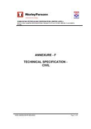
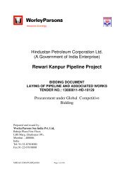
reduction stage and subsequent cooling/condensation. A typical BSR Amine system is shown in<br />
Figure 1. Figure 2 is a typical BSR amine system including the start up blower.<br />
- 3 -
Reducing <strong>Gas</strong> Generator (RGG)<br />
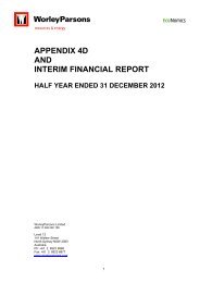
Many competitors use the inline burner design in Figure 3. Burner vibration is common, the<br />
extreme temperature gradient between the combustion and tail gas mixing zones makes it difficult<br />
to optimize skin temperatures at the transition, and a combustion zone shell leak resulting from<br />
localized refractory failure <strong>for</strong>ces a shutdown.<br />
The proposed BSR unit comprises of three process steps:<br />
Reducing <strong>Gas</strong> Generation (RGG) and tail gas preheat<br />
Hydrogenation/Hydrolysis of SO2 and other sulphur species to H2S<br />
<strong>Gas</strong> cooling and waste heat recovery<br />
WorleyParsons proprietary RGG design provides process gas reheating and reducing gas<br />
(H2 and CO) generation in one single process unit. No external supply of hydrogen gas is<br />
required. This feature enhances the reliability of the process unit by eliminating the<br />
uncertainties associated with the availability of external hydrogen supply and the quality of<br />
hydrogen gas.<br />
WorleyParsons design has the following advantages compare to the other licensors.<br />
WorleyParsons Conventional BSR Section<br />
Start Up Blower – reduce the emission during start up to the stack<br />
Caustic wash – reduce breakthrough of SO2 to amine during start up and prevent<br />
degrade of the solvent, No SO2 breakthrough to the amine unit<br />
Stable operation <strong>for</strong> different mode of operation<br />
Good Turn down<br />
No external hydrogen required<br />
Less pressure drop<br />
Less heat loss in RGG configuration<br />
Could be started up independently from SRU’s<br />
No vibration in RGG Burner<br />
No heat Loss in RGG<br />
- 4 -
No Refractory damages as the results of un-uni<strong>for</strong>m heat distribution<br />
Proprietary RGG design provides process gas reheating and reducing gas (H2 and CO)<br />
generation in one single process unit. External supply of hydrogen gas is not required in<br />
most cases.<br />
Start up blower, to eliminate violating the emission during the start up<br />
- 5 -
Figure 1 – WorleyParsons BSR Amine Flow Scheme<br />
- 6 -
Figure 2 – WorleyParsons BSR Amine Flow Scheme with start up blower<br />
- 7 -
Figure 3– Common TGU Feed Heater<br />
By comparison, the WorleyParsons design (Figure 4) employs a brick-lined internal combustion<br />
zone <strong>for</strong> stable combustion unaffected by downstream turbulence. Optimum outer-shell skin<br />
temperatures are easily ensured, heat loss is minimized and potential leakage through the<br />
combustion zone wall does not result in atmospheric release. Some units have been in service<br />
<strong>for</strong> 30+ years with no major refractory repairs. The RGG is typically elevated so that minor<br />
entrained sulphur will free-drain to the reactor (and vaporize).<br />
Figure 4 – WorleyParsons Reducing <strong>Gas</strong> Generator (RGG)<br />
Industry consensus is apparently lacking with regard to the optimum air/fuel ratio. Many<br />
competitors’ units operate at stoichiometric air and rely on supplemental H 2 <strong>for</strong> hydrogenation of<br />
SO 2 and Sx. Perhaps contrary to intuition, equilibrium O 2 is nominally 0.6 % at stoichiometric air,<br />
and only goes to zero at < 90% of stoichiometric. There is experience to suggest that chronic O 2<br />
leakage leads to catalyst sulfation, although there is disagreement within the industry on this<br />
point. Nonetheless, WorleyParsons generally recommends operating at 80% of stoichiometric to<br />
avoid, or at least minimize, O 2 leakage (and also maximize H 2 yield).<br />
The advisability of supplemental H 2 is also a source of controversy. Many clients consider the<br />
availability of import H 2 necessary to minimize the risk of SO 2 breakthroughs, whereas in reality it<br />
is as easy to reduce <strong>Claus</strong> combustion air (with the same effect) as increase H 2 addition. In the<br />
absence of supplemental H 2 , the operator quickly learns the value of monitoring residual H 2 as a<br />
- 8 -
sensitive indicator of <strong>Claus</strong> tail gas ratio, and arguably is more likely to routinely optimize <strong>Claus</strong><br />
air demand when constrained by a limited H 2 supply. Three-stage <strong>Claus</strong> units clearly do not need<br />
supplemental H 2 , while residual H 2 may be marginal with 2-stage units, in which case<br />
supplemental H 2 may be advisable to ensure ability to optimize the <strong>Claus</strong> tail gas H 2 S/SO 2 ratio.<br />
H 2 analyzers based on thermal conductivity measurement are very reliable, with minimal<br />
servicing. Where the TGU is coupled to a single <strong>Claus</strong> train, the H 2 analyzer can in fact supplant<br />
the <strong>Claus</strong> air demand analyzer. Where multiple <strong>Claus</strong> trains are coupled to a single TGU,<br />
combustion air to a <strong>Claus</strong> unit whose air demand analyzer is out of service can be temporarily<br />
adjusted based on TGU residual H 2 .<br />
LP steam injection to the burner in the nominal ratio of 1/1 lb/lb steam/fuel is generally advisable<br />
<strong>for</strong> soot inhibition when firing sub-stoichiometrically, by virtue of the following reactions:<br />
C + H 2 O → CO + H 2 - ΔH<br />
C + 2 H 2 O → CO 2 + 2 H 2 - ΔH<br />
While modern high-intensity burners may be operable at as low as 80% of stoichiometric air<br />
without steam injection, injection is still prudent in view of the possibly of lower air/gas ratios<br />
resulting from meter error or localized fuel-rich zones due to burner damage or fouling. With high<br />
intensity burners, steam injection via a dedicated steam gun is preferred. Otherwise, injection<br />
into the combustion air is the most practical.<br />
Figure 5 – WorleyParsons Reducing <strong>Gas</strong> Generator (RGG) Details<br />
- 9 -
Hydrogenation Reactor<br />
With good catalyst activity and no excessive HCs in the acid gas feed to the Reaction Furnace,<br />
organic residuals in the Absorber offgas should be as shown in Table 1:<br />
Table 1 – Residual Sulphur with Fresh Catalyst<br />
Contaminant<br />
PPMV<br />
Carbonyl sulfide (COS) < 20<br />
Carbon monoxide (CO) < 200<br />
Carbon disulfide (CS 2 ) 0<br />
Methyl mercaptan (CH 3 SH) 0<br />
With fresh conventional catalyst, temperatures of 400-450°F (204-232°C) are typically required to<br />
initiate the hydrogenation reactions, and 540-560°F (282-293°C) <strong>for</strong> hydrolysis. As the catalyst<br />
loses activity with age, progressively higher temperatures may be required. Typically, activity<br />
loss is first evidenced by (1) reduced COS, CS 2 and CO conversion, and (2) potential methyl<br />
mercaptan <strong>for</strong>med by the reaction of CS 2 and H 2 , while hydrogenation of SO 2 and Sx may still be<br />
complete because of the lower initiation temperatures required.<br />
The potential <strong>for</strong>mation of methyl mercaptan at low temperature or impaired catalyst activity is<br />
perhaps not widely appreciated. In cases where the TGU tail gas is discharged without<br />
incineration, nominal mercaptan levels can result in serious nuisance odors. In Stret<strong>for</strong>d units,<br />
there is reason to expect that the mercaptan is oxidized to disulfide oil (DSO) which can impair<br />
froth <strong>for</strong>mation.<br />
Excessive HCs in the SRU acid gas feed will tend to increase the carbon-sulphur compounds in<br />
the Reactor effluent. In the Figure 4 example, HCs in the amine acid gas are evidenced by (1)<br />
increased air demand per volume of gas, (2) increased tail gas volume resulting from the<br />
additional air and HC combustion products, and (3) increased Total Reduced Sulphur (TRS) in<br />
the Absorber offgas – predominantly COS, but also potentially including CS 2 and methyl<br />
mercaptan (RSH). (While TRS also includes H 2 S, the H 2 S content did not increase in this case.)<br />
Low Temperature Hydrogenation Catalyst<br />
WorleyParsons has started offering low temperature catalyst if requested by client as<br />
applicable and meet the project emissions. Low temperature catalyst eliminate of using the<br />
reducing gas generator and indirect heating system could be used instead. Low-temperature<br />
TGU catalysts reportedly capable of operating at inlet temperatures of 210-240°C (410-464°F),<br />
achievable with steam reheat, have recently become available. The primary advantage (in a<br />
new unit) is elimination of the RGG, translating to (1) lower capital cost, (2) operating<br />
simplicity, (3) improved turndown, (4) reduced TGU tail gas volume, (5) reduced CO 2 recycle to<br />
the SRU, and (6) elimination of risk of catalyst damage by RGG misoperation.<br />
- 10 -
Historically, <strong>Claus</strong> tail gas treating units (TGTU) have required reactor inlet temperatures of ~<br />
550°F <strong>for</strong> appreciable hydrolysis of COS, CS 2 and CO, typically requiring preheat by inline firing<br />
or heat exchange with hot oil or heat transfer fluid.<br />
Vendor claims of energy savings are questionable since they tend to (1) assume the plant is long<br />
on LP steam, and (2) disregard the cost of HP steam. Long term per<strong>for</strong>mance of low-temperature<br />
catalysts is still uncertain. The following considerations should be taken into account:<br />
A steam reheater will limit the ability to compensate <strong>for</strong> normal catalyst activity loss with<br />
age, potentially limiting its useful life.<br />
A bottom layer of titania in the first <strong>Claus</strong> converter may be required <strong>for</strong> COS/CS2<br />
hydrolysis.<br />
Higher residual CO levels could mean operating the incinerator at 1500°F (~ 800°C)<br />
instead of 1200°F (~ 650°C).<br />
Incomplete CS2 destruction, and hence methyl mercaptan <strong>for</strong>mation, can result in serious<br />
nuisance odors if the TGU tail gas is discharged without incineration.<br />
Reactor inlet temperatures are only half the story; outlet temperatures are the other half. Any<br />
catalyst will probably initiate SO 2 hydrogenation at 400-450°F (~ 205-230°C) and, with sufficient<br />
temperature rise and excess catalyst, will subsequently achieve virtually complete hydrolysis.<br />
New catalysts by Criterion and Axens require lower activation temperatures achievable by indirect<br />
reheat by 600# steam, thus reducing investment cost, operating complexity and, in some cases,<br />
energy consumption. In addition, lower reactor outlet temperatures may obviate the downstream<br />
waste heat boiler.<br />
While reduced investment and complexity are a given, whether the claimed energy savings is real<br />
is site-specific. Reduced feed preheat energy only constitutes a savings if the plant is already<br />
long on low-pressure waste heat steam (40-70 psig). Otherwise, incremental heat input is fully<br />
recovered. Furthermore, in the absence of a steam surplus, elimination of the waste heat boiler<br />
may have <strong>for</strong>feited recoverable BTUs.<br />
Relative COS, CS 2 and CO conversion efficiencies need to be compared. It is not necessarily<br />
sufficient to achieve regulatory compliance.<br />
COS, CS 2 and CO Hydrolysis using low temperature catalyst<br />
Relative COS, CS 2 and CO conversion efficiencies can be critical. It is not necessarily sufficient<br />
to achieve regulatory compliance.<br />
Regulations could become more stringent in the future.<br />
- 11 -
Some plants must also buy emission credits per pound of SO2 discharged.<br />
Excessive CO residuals could require higher incinerator temperatures, or require<br />
incineration otherwise obviated in units able to achieve TGTU absorber H2S emissions <<br />
10 ppm by the use of acid-aided MDEA.<br />
Hydrolysis of COS, CS 2 and CO typically requires higher temperatures than hydrogenation of SO 2<br />
and S x . Perhaps accordingly, COS, CS 2 and CO conversion efficiencies are the first to suffer as<br />
conventional catalysts lose activity with age. Higher reactor inlet temperatures will tend to<br />
compensate <strong>for</strong> deactivation, thus extending catalyst life considerably. Depending on the design<br />
limits, temperatures can generally be increased by 50-150°F (28-83°C).<br />
Assuming the same holds true <strong>for</strong> the low temperature catalysts, a steam reheater will<br />
substantially limit the extent to which temperatures can be increased, in effect potentially<br />
shortening catalyst life. The lower initiation temperature of the Criterion 734 at start-of-run is thus<br />
significant, as it af<strong>for</strong>ds the greatest margin <strong>for</strong> increase.<br />
At 464°F (240°C) – generally the limit of a 600# steam reheater – hydrolysis of CO, COS and CS 2<br />
approaches that of conventional high temperature catalysts. At 428°F (220°C), however, Axens<br />
concedes that COS/CS 2 conversion must be accomplished in the 1 st <strong>Claus</strong> stage by (1)<br />
supplementing the alumina bed with a bottom layer of expensive titania catalyst, or (2) increasing<br />
the inlet temperature to 550-600°F (288-316°C). The latter will nominally<br />
reduce <strong>Claus</strong> recovery efficiency from<br />
increase SRU tail gas rate<br />
increase TGTU sulphur load<br />
However, the 1 st stage will not effect CO conversion.<br />
Conventional cobalt-moly catalyst will generate minor, but significant, levels of methyl mercaptan<br />
by the reaction of CS 2 and hydrogen at 480°F (249°C) when in good condition, and at much<br />
higher temperatures if the catalyst is aged or damaged. While the manufacturers claim no<br />
residual mercaptans with the low temperature catalysts, there is some uncertainty – in the<br />
author’s view – as to whether that will remain true a few years into the run.<br />
Hydrogen Balance using low temperature catalyst<br />
Compared with firing the feed heater at stoichiometric air and importing H 2 , a steam reheater will<br />
of course have no impact on the H 2 balance. However, many plants avoid the need <strong>for</strong><br />
supplemental H 2 by the use of a reducing gas generator (RGG), typically burning natural gas substoichiometrically<br />
to generate H 2 and CO.<br />
- 12 -
In the absence of an RGG, the alternative is to operate the SRU more air-deficient as necessary<br />
to maintain, say, 2% residual H 2 downstream of the TGTU reactor. This will nominally<br />
reduce <strong>Claus</strong> recovery efficiency<br />
increase SRU tail gas rate<br />
increase TGTU sulphur load<br />
CO 2 Balance using low temperature catalyst<br />
Eliminating the inline burner has the benefit of reducing the TGTU tail gas volume (<strong>for</strong> the<br />
assumed basis with an RGG). Assuming 85% CO 2 slip, the acid gas load on the TGTU amine is<br />
reduced.<br />
Energy Balance using low temperature catalyst<br />
A steam reheater will not only eliminate the following natural gas required by the RGG, but will<br />
also reduce incinerator fuel by virtue of the reduced tail gas rate:<br />
RGG fuel savings<br />
Incinerator fuel savings<br />
Assuming H 2 S/SO 2 = 2 in the SRU tail gas, of supplemental H 2 will be required to maintain a 2%<br />
residual in the TGTU tail gas. As a rule-of-thumb, the value of relatively pure (non-re<strong>for</strong>mer) H 2 is<br />
four times that of natural gas.<br />
Figure 6 represents WorleyParsons BSR/amine with the low temperature catalyst.<br />
- 13 -
SRU TAIL GAS<br />
H 2<br />
HYDROGENATION<br />
REACTOR<br />
HP STEAM<br />
STARTUP<br />
BLOWER<br />
CONTACT<br />
CONDENSER<br />
RECYCLE<br />
WATER<br />
SOUR WATER<br />
BLOWDOWN<br />
DESUPERHEATER<br />
REDUCED TAIL GAS<br />
10% NaOH<br />
TREATED TAIL GAS TO ATMOSPHERE OR INCINERATOR<br />
ABSORBER<br />
ACID GAS<br />
RECYCLE<br />
TO SRU<br />
REFLUX<br />
INTERMITTENT<br />
PURGE TO SWS<br />
RICH AMINE<br />
PROCESS<br />
STEAM<br />
REGENERATOR<br />
LEAN AMINE<br />
Figure 6 – WorleyParsons BSR Amine Flow Scheme with Low Temperature Catalyst<br />
- 14 -
Figure 7 – WorleyParsons Impact of Hydrocarbons in Acid <strong>Gas</strong> to SRU<br />
In the event of a burner trip, there is usually ample time to relight the RGG be<strong>for</strong>e the reactor bed<br />
cools to the point of SO 2 breakthrough. In the Figure 7 example, relight was delayed by a<br />
plugged pilot fuel gas restriction orifice, and the main burner was down ~ one hour (65 minutes).<br />
At all times at least one point in the bed was 510ºF or higher, which likely explains the absence of<br />
an SO 2 breakthrough. By the end of, say, a 2-hour outage, all temperatures would have been <<br />
400ºF, and it is possible that serious SO 2 breakthrough would thus start to occur within 1½-2<br />
hours.<br />
The reactor contained 37.5 Mlb of Criterion 534 cobalt-moly catalyst, a 2-Mlb top layer of ½”<br />
alumina and a 4.5-Mlb support layer of ceramic balls.<br />
- 15 -
Reactor Temperatures<br />
800<br />
700<br />
600<br />
Temperature, F<br />
500<br />
400<br />
300<br />
200<br />
8:00<br />
8:05<br />
8:09<br />
8:14<br />
8:20<br />
8:25<br />
8:30<br />
8:35<br />
8:40<br />
8:45<br />
8:50<br />
8:55<br />
9:00<br />
9:05<br />
9:10<br />
9:14<br />
9:20<br />
9:25<br />
9:29<br />
9:34<br />
9:39<br />
9:44<br />
9:49<br />
9:54<br />
9:59<br />
10:05<br />
10:09<br />
10:15<br />
10:20<br />
10:24<br />
10:29<br />
10:34<br />
10:39<br />
10:44<br />
10:49<br />
10:55<br />
11:00<br />
Figure 8 – WorleyParsons Hydrogenation Reactor Bed Temperatures During RGG Outage<br />
The total tail gas rate is shown in Figure 9. There are actually two identical reactors in parallel,<br />
with only half of the indicated flow through each.<br />
- 16 -
TGTU <strong>Tail</strong> <strong>Gas</strong> Rate<br />
1400<br />
1350<br />
1300<br />
<strong>Tail</strong> gas rate, MSCFH<br />
1250<br />
1200<br />
1150<br />
1100<br />
1050<br />
1000<br />
8:00<br />
8:05<br />
8:09<br />
8:15<br />
8:19<br />
8:24<br />
8:29<br />
8:35<br />
8:40<br />
8:45<br />
8:49<br />
8:54<br />
8:59<br />
9:04<br />
9:09<br />
9:14<br />
9:19<br />
9:24<br />
9:29<br />
9:35<br />
9:40<br />
9:44<br />
9:50<br />
9:55<br />
10:00<br />
10:04<br />
10:09<br />
10:15<br />
10:19<br />
10:24<br />
10:29<br />
10:34<br />
10:39<br />
10:44<br />
10:49<br />
10:54<br />
11:00<br />
Figure 9 – WorleyParsons TGU <strong>Tail</strong> <strong>Gas</strong> Rate During RGG Outage<br />
Resultant TRS (measured at the absorber outlet) and SOx emissions are shown in Figure 10.<br />
- 17 -
Emissions<br />
400<br />
350<br />
F-754<br />
absorber TRS<br />
300<br />
PPM, corrected to air-free basis<br />
250<br />
200<br />
150<br />
100<br />
50<br />
0<br />
8:00<br />
8:04<br />
8:10<br />
8:14<br />
8:19<br />
8:25<br />
8:30<br />
8:34<br />
8:40<br />
8:45<br />
8:50<br />
8:55<br />
9:00<br />
9:05<br />
9:10<br />
9:15<br />
9:20<br />
9:25<br />
9:30<br />
9:34<br />
9:39<br />
9:45<br />
9:49<br />
9:54<br />
9:59<br />
10:04<br />
10:09<br />
10:14<br />
10:19<br />
10:24<br />
10:29<br />
10:35<br />
10:39<br />
10:44<br />
10:49<br />
10:54<br />
10:59<br />
Figure 10–WorleyParsons Impact of RGG Outage on Emissions<br />
Contact Condenser (2-Stage Quench)<br />
Common industry practice is to cool the reduced tail gas from the reactor by the generation of LP<br />
waste heat steam followed by direct quench with a recirculating water stream to cool it to 90-<br />
100°F (~ 30-40°C), thus condensing most of the water vapor which accounts <strong>for</strong> ~ 35% of the<br />
stream.<br />
WorleyParsons utilizes a unique 2-stage tower comprised of a bottom Desuperheater section and<br />
top Contact Condenser.<br />
The contact condenser has 2 sections, the first section de-superheats the gas and scrub<br />
any SO 2 may breakthrough from hydrogenation reactor, and the second section cools the<br />
gas and condensate the water, there<strong>for</strong>e there is no need <strong>for</strong> make up water to maintain<br />
the caustic concentration. The condense water will provide the water to maintain the<br />
caustic concentration. We do not have continuous purge, but we provide water make up<br />
<strong>for</strong> the water is evaporated, just like any other quench system.<br />
- 18 -
<strong>Tail</strong> gas is desuperheated in the lower section of the contact condenser by a circulating<br />
water stream. This water is maintained alkaline to protect against any SO 2 breakthrough<br />
from the reactor. In the upper packed section of the tower, most of the water vapor in the<br />
tail gas is condensed by direct contact with a circulating stream of cooled water. A pH<br />
analyzer with a low-pH alarm is installed in the quench water circulation line and will<br />
indicate when the pH of the quench water is reducing, from either a breakthrough of SO 2 ,<br />
or incomplete reduction of the sulphur compounds in the gas stream from the<br />
Hydrogenation Reactor.<br />
(Figure 1 and 2) A 10 %-wt NaOH solution is recirculated through the Desuperheater to capture<br />
SO 2 potentially resulting from a process upset, while also cooling it to its dewpoint of ~ 165°F (~<br />
75°C). The only cooling is by vaporization. The gas is further cooled to 90-100°F (~ 30-40°C) by<br />
direct contact with an externally cooled recycle water stream in the upper Contact Condenser<br />
section. A recycle water slipstream is returned to the Desuperheater on Desuperheater levelcontrol<br />
via two bubble-cap wash trays to capture entrained caustic.<br />
A blowdown slipstream of recycle water is purged, usually to sour water, on Contact Condenser<br />
level-control. While the recycle water is usually classified as sour water, the H 2 S content is<br />
typically < 50 ppmv by virtue of CO 2 saturation. In situations where the increased load on the<br />
plant sour water stripper is undesirable, a simple blowdown stripper is occasionally provided at<br />
the TGU. This typically involves LP stripping steam injection (as opposed to a reboiler) and<br />
return of the uncondensed overhead stream to the Desuperheater.<br />
Startup Blower<br />
WorleyParsons provide a start up blower on the contact condenser overhead to eliminate flaring<br />
large quantities of H2S to atmosphere and to prevent violation of the emission. For those cases<br />
that a booster blower required then booster blower will have dual function as a start up blower<br />
and as a booster blower.<br />
Booster Blower<br />
Many of the <strong>Claus</strong> units that are in operation do not have enough pressure to handle a new tail<br />
gas unit in other words the provision of operating the <strong>Claus</strong> unit at the higher pressure was not<br />
considered, if the source pressure changed the existing amine unit requires higher reboiler duty<br />
and in most cases required significant changes in the amine unit. WorleyParsons have been<br />
offering a booster blower in the tail gas unit to overcome the pressure limitation.<br />
Retrofit <strong>Tail</strong> <strong>Gas</strong> Units will typically require a booster blower downstream of the Contact<br />
Condenser to overcome the additional pressure drop. The blower is located after the Contact<br />
Condenser to minimize the actual volume (by virtue of cooling and condensation), and be<strong>for</strong>e the<br />
Absorber to take advantage of the higher pressure.<br />
With proper design and operation, booster blowers are inherently very reliable, requiring minimal<br />
maintenance. Typically, the case is cast iron or carbon steel, with an aluminum impellor. N 2 -<br />
- 19 -
purged tandem shaft seals (typically carbon rings) eliminate process leakage to atmosphere on<br />
the discharge end as well as air aspiration into the process on the suction end, which is typically<br />
at a vacuum.<br />
Though often viewed as a liability by clients, booster blowers arguably improve operability in<br />
several ways:<br />
By recirculating tail gas, the TGU can be started up and shut down independent of the<br />
SRUs.<br />
<strong>Tail</strong> gas recycle ensures process stability at high SRU turndown by (1) avoiding undue<br />
RGG burner turndown potentially conducive to sooting due to poor mixing or air/gas<br />
flowmeter inaccuracy, and (2) diluting potentially high SO2 levels often typical of high SRU<br />
turndown. With advance warning, tail gas recycle can avoid RGG shutdown in the event of<br />
an SRU trip.<br />
By routing the SRU and TGU tail gas to the incinerator via a common header, a vacuum<br />
can be maintained at the RGG without risk of leaking air from the incinerator back into the<br />
TGU, thus potentially further increasing SRU capacity. In the event that the tail gas<br />
bypass valve leaks, clean TGU tail gas is recycled to the RGG rather than SRU tail gas<br />
bypassing the TGU (as when the RGG pressure is positive). Any such reverse flow will<br />
improve bypass valve reliability by excluding sulphur vapor, and the valve can be partially<br />
stroked periodically to verify operability without increased emissions.<br />
Figure 11– WorleyParsons RGG Vacuum Operation<br />
In the absence of a booster blower, a single startup blower recycle is usually provided <strong>for</strong> tail gas<br />
recycle. While these machines tend to be less sophisticated, N 2 -purged tandem shaft seals are<br />
still required.<br />
- 20 -
The overall configuration of using the booster blower is shown in the Figure 10. This configuration<br />
could be used with low temperature catalyst and indirect reheater instead of the RGG.<br />
RGG<br />
HYDROGENATION<br />
REACTOR<br />
SRU TAIL GAS<br />
REACTOR<br />
EFFLUENT<br />
COOLER<br />
HY-250<br />
TO<br />
INCINERATOR<br />
PC<br />
HY-251<br />
HC<br />
CONTACT<br />
CONDENSER<br />
ABSORBER<br />
FC<br />
BOOSTER<br />
BLOWER<br />
XY-292<br />
DESUPERHEATER<br />
WATER<br />
WASH<br />
Figure 12 – WorleyParsons BSR-TGU with Booster Blower configuration<br />
- 21 -
Solvent <strong>Selection</strong> <strong>Criteria</strong> in the <strong>Tail</strong> <strong>Gas</strong> Unit<br />
The most common solvent is 40-45 %-wt MDEA, (HS-101, or similar) designed <strong>for</strong> a maximum<br />
rich loading of 0.1 mol acid gas (H 2 S + CO 2 ) per mol amine with typical emission reduction to ~<br />
100 ppmv H 2 S. Cooling of the lean amine to at least 100°F (38°C) is important <strong>for</strong> minimization of<br />
emissions and amine circulation rate. Specialty TGU amines are essentially pH-modified MDEA<br />
to facilitate stripping to lower residual acid gases <strong>for</strong> treatment to < 10 ppm H 2 S, potentially<br />
obviating incineration. CO 2 slip is also improved. These products are variously marketed as<br />
Dow UCARSOL HS-103<br />
Ineos <strong>Gas</strong>/Spec TG-10<br />
Huntsman MS-300.<br />
An alternative to MDEA is ExxonMobil’s Flexsorb SE, a proprietary hindered amine patented by<br />
Exxon in partnership with the Ralph M. Parsons Company. The main advantage is a 20-30%<br />
reduction in circulation rate. The solvent is much more stable than MDEA, but is also more<br />
expensive. Flexsorb SE Plus is also available <strong>for</strong> treatment to < 10 ppmv H 2 S. Both solvents<br />
require a license agreement with ExxonMobil.<br />
It used to be assumed that TGU carbon filtration was not required in view of the absence of<br />
hydrocarbons. For MDEA-based solvents, at least, this has proven untrue, presumably due to<br />
the generation of surfactant amine degradation products.<br />
Solvent Applications<br />
FLEXSORB® SE Selective removal of H2S<br />
FLEXSORB® SE Plus Selective removal of H2S to less than 10 ppm<br />
FLEXSORB® SE Hybrid Removal of H2S, CO2, and sulphur compounds (mercaptans and<br />
COS)<br />
In sulphur plant tail gas applications, FLEXSORB® SE solvents can use as little as one<br />
half of the circulation rate and regeneration energy typically required by MDEA based<br />
solvents. CO2<br />
Rejection in TGTU applications is very high, typically >90% rejection.<br />
Flexsorb solvents offer other advantages compare to the other amine solvents <strong>for</strong><br />
instance, most of applications requires no reclaiming, have good operating experience, low<br />
corrosion, and low foaming due to low hydrocarbon absorption, by providing water wash of<br />
treated gas at low pressure system amine losses are minimum.<br />
- 22 -
DEGSulf Sub Dew Point process by WorleyParsons& DEG-ITS<br />
DEGSulf-SDP is a sulphur recovery process of the <strong>Claus</strong> type. A plant consists typically of a<br />
<strong>Claus</strong> furnace plus downstream just 2 catalytic reactors and sulphur condensers. The reactors<br />
contain a heat exchanger which keeps the operating temperature <strong>for</strong> each reactor at its optimum.<br />
This simple system, described in detail below, allows reaching up to 99.85% sulphur recovery<br />
rate.<br />
<strong>Gas</strong> containing hydrogen sulfide (=H 2 S) is sent to the <strong>Claus</strong> furnace. There it is burned with a<br />
stoichiometric deficiency of air so that one third of the H 2 S is converted to SO 2 . The residual H 2 S<br />
and the SO 2 react to elemental sulphur according to the <strong>Claus</strong> reaction (I): (I) 2 H 2 S + SO 2 3/x<br />
Sx + 2 H 2 O x = 2,4,6,8 indicates the different sulphur modifications Typically a recovery rate of<br />
over 60 % is realized in the furnace. <strong>Gas</strong> from the waste heat boiler and sulphur condenser of the<br />
<strong>Claus</strong> furnace is reheated by a hot gas bypass. It then flows via 4-way valve to the adiabatic part<br />
of the first reactor, which is filled with a catalyst of high COS and CS 2 conversion capability.<br />
Residual traces of free oxygen from the <strong>Claus</strong> furnace are eliminated in this layer. The gas enters<br />
the cooled section of the reactor bed at a temperature of between 300 and 350°C. Cooling takes<br />
place by evaporating boiler feed water or hot oil. Here the <strong>Claus</strong> reaction continues further close<br />
to the equilibrium at appr. 260 °C, which is slightly above the sulphur dew point at outlet<br />
conditions. The gas leaves the reactor and passes via the second 4-way valve to the only<br />
sulphur condenser of the catalytic part. The sulphur condenser operates at gas outlet<br />
temperatures of between 135 °C and 150 °C and produces low pressure steam. The process gas<br />
leaves the condenser through a mist eliminator. Total sulphur recovery up to this point exceeds<br />
95 %. The gas is reheated again be<strong>for</strong>e entering the second reactor which can be regarded as<br />
the tail gas treatment. In the steam jacketed pipe the temperature is raised by appr. 20°C in order<br />
to be safely above the sulphur dew point. In the adiabatic zone of the second reactor the <strong>Claus</strong><br />
reaction proceeds. <strong>Claus</strong> gas then enters the cooled part of the second reactor, where the<br />
reaction temperature is lowered to 100 - 125 °C by the cooling coils. Elemental sulphur from the<br />
adiabatic zone and <strong>for</strong>med in the cooled zone is adsorbed by the aluminum-based catalyst. The<br />
coils keep the reactor outlet temperature at constant level throughout the complete adsorption<br />
period. The evenly low temperature throughout the bed causes a substantial increase of the<br />
sulphur recovery rate compared to state-of-the-art processes.<br />
- 23 -
F-201<br />
REACTION<br />
FURNACE<br />
E-201<br />
WASTE HEAT<br />
BOILER<br />
E-202<br />
SULFUR<br />
CONDENSER<br />
E-203<br />
NO. 1<br />
REHEATER<br />
R-201<br />
NO. 1<br />
REACTOR<br />
V-203<br />
NO. 1<br />
REACTOR<br />
STEAM DRUM<br />
E-205<br />
NO. 1<br />
REACTOR STEAM<br />
CONDENSER<br />
E-204<br />
NO. 2<br />
REHEATER<br />
R-202<br />
NO. 2<br />
REACTOR<br />
V-204<br />
NO. 2<br />
REACOR<br />
STEAM DRUM<br />
E-206<br />
NO. 2<br />
REACTOR STEAM<br />
CONDENSER<br />
T-201<br />
SULFUR PIT<br />
PA-201<br />
DEGASSING<br />
PACKAGE<br />
ED-201<br />
SULFUR PIT<br />
VENT<br />
EDUCTOR<br />
PC<br />
FC<br />
ACID GAS FROM<br />
KO DRUM<br />
- X<br />
FC<br />
TC<br />
TC<br />
X<br />
+<br />
X<br />
X<br />
MP<br />
STEAM<br />
MP<br />
STEAM<br />
E-205 E-206<br />
M<br />
MP<br />
STEAM<br />
E-203 E-204<br />
PC<br />
LI<br />
R-201<br />
PC<br />
LI<br />
R-202<br />
TAIL GAS TO<br />
INCINERAOR<br />
F-201<br />
E-201<br />
V-203<br />
CONDENSATE<br />
T<br />
V-204<br />
PC<br />
FC<br />
NH3 GAS FROM<br />
KO DRUM<br />
LC<br />
T<br />
BFW<br />
CONDENSATE<br />
TC<br />
REACTOR<br />
SWITCHING<br />
CONTROLS<br />
BFW<br />
TC<br />
AC<br />
M<br />
E-202<br />
H2S/SO2<br />
BLOWDOWN<br />
VENT<br />
FC<br />
FC<br />
BFW<br />
B-201<br />
FC<br />
VENT GAS TO<br />
INCINERATOR<br />
MP STEAM<br />
ED-201<br />
PA-201<br />
SULFUR<br />
COMBUSTION AIR<br />
FROM SPARE<br />
BLOWER<br />
T-201<br />
P-203A/B<br />
M<br />
P-204A/B<br />
M<br />
AIR<br />
B-201<br />
COMBUSTION AIR<br />
BLOWER<br />
P-203A/B<br />
SULFUR<br />
DEGASSING PUMP<br />
P-204A/B<br />
SULFUR TRANSFER<br />
PUMP<br />
PROCESS FLOW DIAGRAM - SULFUR RECOVERY UNIT – TRAIN 2<br />
Figure 13, WorleyParsons /DEG-ITS Sub Dew Point process (DEGSULF)<br />
- 24 -
Ammonia Destruction in a TGU (RAC TM )<br />
The general industry consensus is that the amount of ammonia that can be conventionally processed in<br />
the SRU is limited to 30-35 %-vol on a wet basis. With what appears to be a trend toward higher-nitrogen<br />
crudes, refiners are increasingly faced with the need <strong>for</strong> alternative processing schemes, as well as SRU<br />
debottlenecking. With sour water stripping schemes such as Chevron’s Waste Water Treatment (WWT)<br />
process <strong>for</strong> separating H 2 S and NH 3 , producing a pure marketable NH 3 product is relatively difficult<br />
compared with bulk separation of NH 3 containing minor H 2 S.<br />
WorleyParsons’ Rameshni Ammonia Conversion (RAC TM ) process, <strong>for</strong> which a patent is pending, substoichiometrically<br />
combusts a high-NH 3 H 2 S-contaminated stream in the RGG. (Figure 14) Typically, the<br />
NH 3 -gas heat release will exceed that required to reheat the <strong>Claus</strong> tail gas, thus necessitating a waste<br />
heat boiler prior to the TGU reactor. A supplemental natural gas fire ensures process stability in the<br />
event of NH 3 -gas curtailment. Sub-stoichiometric combustion of the NH 3 -gas generates supplemental H 2<br />
<strong>for</strong> the hydrogenation reactor and minimizes NOx. Most of any NOx that is made is reduced in the<br />
reactor. Minor unconverted NH 3 is automatically recycled to the sour water stripper via the Contact<br />
Condenser blowdown.<br />
Table 2 defines the nominal feed bases <strong>for</strong> two hypothetical cases, where Case 1 involves a pure NH 3<br />
stream, and Case 2 a high-NH 3 low-H 2 S stream. Table 2 compares the nominal impact on key<br />
parameters of routing those NH 3 streams to the TGU (Cases 1b and 2b) as opposed to the SRU reaction<br />
furnace (Case 1a and 2a).<br />
- 25 -
Figure 14 – WorleyParsons Ammonia Destruction in TGU (RAC TM )<br />
- 26 -
Table 2 – WorleyParsons RAC TM Hypothetical Feed Streams<br />
Fresh Feed <strong>Gas</strong>, Mol %<br />
Component<br />
Case 1 Case 2<br />
Acid <strong>Gas</strong> NH 3 <strong>Gas</strong> Acid <strong>Gas</strong> NH 3 <strong>Gas</strong><br />
H 2 S 80 80 5<br />
CO 2 16 16<br />
NH 3 96 65<br />
H 2 O 4 4 4 30<br />
Total 100 100 100 100<br />
Fresh feed, LTPD S 100 95 5<br />
NH 3 / total fresh feed, mol % 29 28<br />
Key Parameter<br />
Table 3 – WorleyParsons RAC TM Impact on Key Parameters<br />
Comparison<br />
Case 1 NH 3 <strong>Gas</strong> Route<br />
Case 1A<br />
SRU<br />
Case 1B<br />
TGU<br />
∆<br />
%<br />
Case 2 NH 3 <strong>Gas</strong> Route<br />
Case 2A<br />
SRU<br />
Case 2B<br />
TGU<br />
<strong>Claus</strong> tail gas, MSCFH 689 364 -47 760 346 -54<br />
<strong>Claus</strong> recovery, % 92.7 96.5 92.3 96.5<br />
RGG fuel, MMBTU/hr 10.4 0.5 -95 11.4 0.5 -96<br />
TGU amine AG, MSCFH 17.5 10.1 -42 18.1 15.3 -15<br />
∆<br />
%<br />
BSR Selectox<br />
Selectox catalyst is a proprietary catalyst patented by WorleyParsons <strong>for</strong> low-temperature H 2 S-oxidation<br />
and <strong>Claus</strong>-reaction catalyst development by the Ralph M. Parsons Company and Unocal. Reduced tail<br />
gas from the BSR Contact Condenser is steam-reheated to about 400°F (~ 200°C) and combined with a<br />
stoichiometric quantity of air in the reactor to produce elemental sulphur, which is subsequently<br />
condensed. (Figure 15) Overall recoveries of 98.5-99.5% are achievable. The reactor inlet is limited to 5<br />
%-vol H 2 S, above which recycle dilution (or inter-bed heat removal) is necessary to limit the exothermic.<br />
- 27 -
SRU TAIL GAS<br />
NATURAL GAS<br />
COMBUSTION AIR<br />
RGG<br />
CONTACT<br />
CONDENSER<br />
RECYCLE<br />
WATER<br />
SOUR WATER<br />
BLOWDOWN<br />
HYDROGENATION<br />
REACTOR<br />
DESUPERHEATER<br />
STEAM<br />
REHEATER<br />
REDUCED TAIL GAS<br />
10% NaOH<br />
AIR<br />
SELECTOX<br />
REACTOR<br />
LP STEAM<br />
SULFUR<br />
CONDENSER<br />
TAIL GAS TO<br />
INCINERATOR<br />
SULFUR<br />
Figure 15 – WorleyParsons BSR Selectox<br />
- 28 -
WorleyParsons Current Case Histories<br />
The following are the case histories of the different projects have been recently designed by<br />
WorleyParsons.<br />
Project Case 1<br />
WorleyParsons designed a new tail gas unit <strong>for</strong> a US refinery to meet the emission requirements. The<br />
following were the key elements of the project.<br />
The existing sulphur plant did not have adequate pressure to handle the tail gas pressure<br />
Total H2S of less than 100 ppm<br />
COS, CS2 hydrolysis<br />
SO2 concentration at reactor outlet<br />
Hydraulic and unit capacity<br />
WorleyParsons evaluated this project and the final design was based according to the following criteria.<br />
Reducing gas generator (RGG) was selected to achieve high temperature in the hydrogenation<br />
reactor <strong>for</strong> COS and CS2 hydrolysis without changing any catalyst in the existing SRU.<br />
Flexsorb solvent was selected because it requires less circulation rate compare to the other tail<br />
gas amine solvent There<strong>for</strong>e, the capital cost reduced.<br />
A booster blower is provided to boost the pressure in the tail gas unit downstream of the quench<br />
section. The booster blower has dual function where it will be used as a start up blower to<br />
eliminate large volume of H2S to the flare and recycle back to the unit and the booster blower will<br />
boost the pressure in the unit.<br />
The final design is according to the Figure 12 that is provided in this paper.<br />
Project Case 2<br />
WorleyParsons has designed two new tail gas units one <strong>for</strong> a US refinery and one <strong>for</strong> a Canadian refinery<br />
with the following configuration.<br />
The existing sulphur plant did not have adequate pressure to handle the tail gas pressure<br />
Total H2S of less than 100 ppm<br />
COS, CS2 hydrolysis<br />
- 29 -
Hydraulic and unit capacity<br />
WorleyParsons evaluated this project and the final design was based according to the following criteria.<br />
Reducing gas generator (RGG) was selected to achieve high temperature in the hydrogenation<br />
reactor <strong>for</strong> COS and CS2 hydrolysis without changing any catalyst in the existing SRU.<br />
MDEA solvent was selected simply they do not need to deal with two different solvent <strong>for</strong> the<br />
amine and tail gas unit and there was no cost saving to use other solvent.<br />
A booster blower is provided to boost the pressure in the tail gas unit downstream of the quench<br />
section. The booster blower has dual function where it will be used as a start up blower to<br />
eliminate large volume of H2S to the flare and recycle back to the unit and the booster blower will<br />
boost the pressure in the unit.<br />
The final design is according to the Figure 2 that is provided in this paper.<br />
Project Case 3<br />
WorleyParsons has designed a new sulphur recovery and BSR/MDEA tail gas unit <strong>for</strong> a refinery in South<br />
America with the following configuration.<br />
Total H2S of less than 100 ppm<br />
COS, CS2 hydrolysis<br />
Hydraulic and unit capacity<br />
WorleyParsons evaluated this project and the final design was based according to the following criteria.<br />
Low temperature catalyst is selected in the tail gas unit and the first reactor bed in the <strong>Claus</strong> unit<br />
will contain some Ti catalyst<br />
MDEA solvent was selected simply they do not need to deal with two different solvent <strong>for</strong> the<br />
amine and tail gas unit and there was no cost saving to use other solvent.<br />
A n start up blower is provide only <strong>for</strong> start up purposes and will not be used at normal operation<br />
except where is the very low turn down and may be used to boost the pressure.<br />
The final design is according to the Figure 6 that is provided in this paper.<br />
- 30 -
References<br />
1. Ammonia Destruction in a <strong>Claus</strong> <strong>Tail</strong> <strong>Gas</strong> <strong>Treating</strong> Unit, by M. Rameshni, presented at British<br />
Sulphur Conference, Canada, 2007<br />
2. Operating experience of a 2-reactor <strong>Claus</strong> plant <strong>for</strong> up to 99.85% sulphur recovery, by J. Kunkel,<br />
P.M. Heisel, LINDE AG, Ulf Nilsson, Peter Eriksson, NYNÄS AB<br />
- 31 -