Version 1 Harley-Davidson® Hitch Installation Guide - Bushtec Trailers
Version 1 Harley-Davidson® Hitch Installation Guide - Bushtec Trailers
Version 1 Harley-Davidson® Hitch Installation Guide - Bushtec Trailers

Create successful ePaper yourself
Turn your PDF publications into a flip-book with our unique Google optimized e-Paper software.
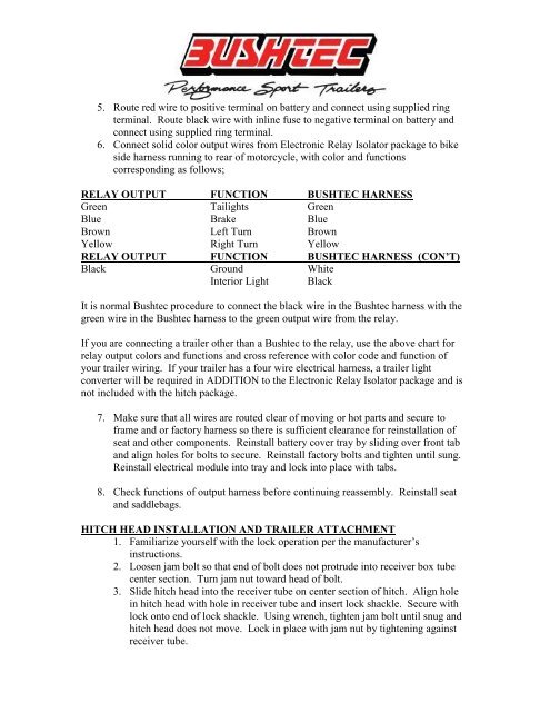
5. Route red wire to positive terminal on battery and connect using supplied ring<br />
terminal. Route black wire with inline fuse to negative terminal on battery and<br />
connect using supplied ring terminal.<br />
6. Connect solid color output wires from Electronic Relay Isolator package to bike<br />
side harness running to rear of motorcycle, with color and functions<br />
corresponding as follows;<br />
RELAY OUTPUT FUNCTION BUSHTEC HARNESS<br />
Green Tailights Green<br />
Blue Brake Blue<br />
Brown Left Turn Brown<br />
Yellow Right Turn Yellow<br />
RELAY OUTPUT FUNCTION BUSHTEC HARNESS (CON’T)<br />
Black Ground White<br />
Interior Light Black<br />
It is normal <strong>Bushtec</strong> procedure to connect the black wire in the <strong>Bushtec</strong> harness with the<br />
green wire in the <strong>Bushtec</strong> harness to the green output wire from the relay.<br />
If you are connecting a trailer other than a <strong>Bushtec</strong> to the relay, use the above chart for<br />
relay output colors and functions and cross reference with color code and function of<br />
your trailer wiring. If your trailer has a four wire electrical harness, a trailer light<br />
converter will be required in ADDITION to the Electronic Relay Isolator package and is<br />
not included with the hitch package.<br />
7. Make sure that all wires are routed clear of moving or hot parts and secure to<br />
frame and or factory harness so there is sufficient clearance for reinstallation of<br />
seat and other components. Reinstall battery cover tray by sliding over front tab<br />
and align holes for bolts to secure. Reinstall factory bolts and tighten until sung.<br />
Reinstall electrical module into tray and lock into place with tabs.<br />
8. Check functions of output harness before continuing reassembly. Reinstall seat<br />
and saddlebags.<br />
HITCH HEAD INSTALLATION AND TRAILER ATTACHMENT<br />
1. Familiarize yourself with the lock operation per the manufacturer’s<br />
instructions.<br />
2. Loosen jam bolt so that end of bolt does not protrude into receiver box tube<br />
center section. Turn jam nut toward head of bolt.<br />
3. Slide hitch head into the receiver tube on center section of hitch. Align hole<br />
in hitch head with hole in receiver tube and insert lock shackle. Secure with<br />
lock onto end of lock shackle. Using wrench, tighten jam bolt until snug and<br />
hitch head does not move. Lock in place with jam nut by tightening against<br />
receiver tube.