Antennas + Coaxial Cables for Railway, Light Rail ... - Composites
Antennas + Coaxial Cables for Railway, Light Rail ... - Composites
Antennas + Coaxial Cables for Railway, Light Rail ... - Composites

Create successful ePaper yourself
Turn your PDF publications into a flip-book with our unique Google optimized e-Paper software.
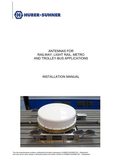
ANTENNAS FOR<br />
RAILWAY, LIGHT RAIL, METRO<br />
AND TROLLEY-BUS APPLICATIONS<br />
INSTALLATION MANUAL<br />
This document/drawing contains confidential in<strong>for</strong>mation belonging to HUBER+SUHNER AG - Switzerland<br />
and may not be used, copied or disclosed without the written consent of HUBER+SUHNER AG – Switzerland
1 INTRODUCTION.........................................................................................................................3<br />
2 INSTALLATION..........................................................................................................................3<br />
2.1 Mechanical dimensions............................................................................................................3<br />
2.2 Installation directly on the roof................................................................................................3<br />
2.2.1 Type of roof of the vehicle ....................................................................................................3<br />
2.2.2 Preparation of the roof..........................................................................................................6<br />
2.2.3 Mounting of the antenna.......................................................................................................7<br />
2.2.4 Connecting of the cables ......................................................................................................7<br />
2.2.5 Sealing..................................................................................................................................7<br />
2.2.6 Corrosion ..............................................................................................................................7<br />
2.3 Installation on a bracket ...........................................................................................................8<br />
2.3.1 Special installation on the side of a train’s roof ....................................................................9<br />
2.3.2 Stability .................................................................................................................................9<br />
2.3.3 Compliance with sealing requirements.................................................................................9<br />
2.3.4 Short circuit protection........................................................................................................11<br />
3 SPECIAL POINTS ....................................................................................................................11<br />
3.1 <strong>Antennas</strong> with active GPS......................................................................................................11<br />
3.2 <strong>Antennas</strong> with passive GPS...................................................................................................11<br />
2<br />
HUBER+SUHNER – Excellence in Connectivity Solutions
1 INTRODUCTION<br />
This document is a guideline <strong>for</strong> the installation of the Sencity ® <strong>Rail</strong>, Sencity ® <strong>Rail</strong> Excel or Sencity ®<br />
Avant antennas on a vehicle roof. It gives additional in<strong>for</strong>mation to the mounting instruction and the<br />
datasheet. For defining the right installation of the antenna, the in<strong>for</strong>mation on the mounting instruction<br />
must be respected.<br />
2 INSTALLATION<br />
The following chapters provide further details about correct installation such as the roof’s mechanical<br />
stability and the correct preparation of the roof as well as installation requirements to ensure<br />
security in case of accidents.<br />
2.1 Mechanical dimensions<br />
There are minor differences between the different Sencity ® <strong>Rail</strong>, Sencity ® <strong>Rail</strong> Excel and Sencity<br />
® Avant antennas. The specific in<strong>for</strong>mation can be found on the datasheet and the mounting<br />
instruction.<br />
2.2 Installation directly on the roof<br />
2.2.1 Type of roof of the vehicle<br />
Depending of the roof additional precautions have to be made. In case of doubts, the installation<br />
has to be discussed with the train builder.<br />
2.2.1.1 Stable metal roof<br />
Three issues in regards to the metal roof need to be considered be<strong>for</strong>e installation:<br />
1. Planarity of the roof<br />
The planarity of the train’s roof must be checked be<strong>for</strong>e the installation of any antennas. Exact in<strong>for</strong>mation<br />
about planarity can be found in the mounting instruction which is delivered with each<br />
antennas.<br />
If this requirement is not respected during installation the risk of death when an accident<br />
occurs is dramatically increased.<br />
2. Conductivity of the roof<br />
After the preparation of the roof, its conductivity on the contact area with the antenna must be<br />
checked using a proper ohmmeter.<br />
If this requirement is not respected during installation the risk of death when an accident<br />
occurs is dramatically increased.<br />
3<br />
HUBER+SUHNER – Excellence in Connectivity Solutions
2.2.1.2 Thin metal roof<br />
Three issues in regards to the metal roof need to be considered be<strong>for</strong>e installation and are described<br />
below. The main problem existing with thin metal roof is ensuring a sufficient contact between<br />
the antenna and the vehicle, if this is not achieved it will result in a non-compliance to UIC<br />
533 standard and the risk of death in case of accident. Careful analysis with FMEA needs to be<br />
undertaken.<br />
1. Stability of the roof<br />
The stability of the roof must be checked be<strong>for</strong>e the installation of any antennas. Washers which<br />
have a sufficient diameter need to be utilised (see figures 1 and 2). HUBER+SUHNER recommends<br />
the utilisation of washers according to the ISO 7093 standard (stainless steel A2, 140 HV,<br />
d2=24, d1=8.4). This recommendation will ensure sufficient contact between the antenna and the<br />
roof of the vehicle but does NOT help to rein<strong>for</strong>ce the roof. The stability of the roof needs to be<br />
analyzed taking in account the wind load of the antenna (depending on the speed of the vehicle),<br />
the weight of the antenna, a possible shock scenarios caused by objects (i.e. birds) and the position<br />
on the roof. If in doubts, FEM (Finite Element Method) simulations need to be undertaken be<strong>for</strong>e<br />
installing any antennas.<br />
If this requirement is not respected during installation the risk of death when an accident<br />
occurs is dramatically increased.<br />
Figure 1<br />
4<br />
HUBER+SUHNER – Excellence in Connectivity Solutions
Figure 2<br />
2. Planarity of the roof<br />
The planarity of the train’s roof must be checked be<strong>for</strong>e the installation of any antennas. Stability<br />
problems or uneven parts of the roof will cause problems with the sealing or will lead to an insufficient<br />
contact between the antenna and the roof.<br />
If this requirement is not respected during installation the risk of death when an accident<br />
occurs is dramatically increased.<br />
3. Conductivity of the roof<br />
After the preparation of the roof, its conductivity on the contact area with the antenna must be<br />
checked using a proper ohmmeter.<br />
If this requirement is not respected during installation the risk of death when an accident<br />
occurs is dramatically increased.<br />
2.2.1.3 Thin polymer roof<br />
As the roof of the vehicle is made of polymer (typically a mix of epoxy and fibre glass) the roof<br />
does not need to be grounded such as seen in the UIC 533 standard. In case of contact between<br />
the power line and the roof a short circuit will then only appear when the overhead line is in physically<br />
contact with the antenna. A short circuit is possible due to the fact that each antenna is connected<br />
to the train equipment through the coaxial cable which travels somewhere with inside the<br />
vehicle. Depending on the application, the coaxial cable will be located close to passengers or to<br />
the driver resulting in risk of death when an accident occurs.<br />
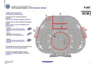
1. Grounding of antenna on integrated metal plate<br />
The vehicle will need to be rein<strong>for</strong>ced by making a large cut in the polymer and integrating a large<br />
thick metal plate (<strong>for</strong> the characteristics of this metal plate refer to the chapter 2.2.1.1). The antenna<br />
is mounted on the metal plate (see figure 3b).<br />
5<br />
HUBER+SUHNER – Excellence in Connectivity Solutions
For better passenger protection during an accident, a proper grounding cable or copper busbar<br />
should be utilised.<br />
2. Grounding of antenna via the grounding kit<br />
If the antenna offers the possibility of using the grounding kit, the copper busbar can be mounted<br />
via the grounding kit directly to the antenna (see Figure 3a). The copper busbar has to have a sufficient<br />
large cross section surface in order to discharge the possible 40’000 amperes (larger than<br />
120 mm 2 <strong>for</strong> copper). The copper busbar has to be fixed to a rigid element nearby in order to withstand<br />
the strong mechanical <strong>for</strong>ce which results in case of a sudden high current short circuit.<br />
If this possibility is not available, the antenna has to be mounted on a grounded integrated metal<br />
plate (see point 1).<br />
If this requirement is not respected during installation the risk of death when an accident<br />
occurs is dramatically increased.<br />
Figure 3a<br />
Figure 3b<br />
For some Sencity ® <strong>Rail</strong> antennas, the metal plate has to have a certain size in order to ensure the<br />
electrical per<strong>for</strong>mance of the antenna. The size of this required ground plane can be found on the<br />
datasheet.<br />
2.2.2 Preparation of the roof<br />
To comply with all security requirements, the area of the roof where the antenna is mounted, must<br />
be free of paint and contaminants like paint, non-conductive surface treatment, dirt, corrosion,<br />
brake dust, oil or fat. In case of an aluminium roof, the aluminium in direct contact with the antenna<br />
must not be anodised.<br />
If this requirement is not respected during installation the risk of death when an accident<br />
occurs is dramatically increased.<br />
6<br />
HUBER+SUHNER – Excellence in Connectivity Solutions
2.2.3 Mounting of the antenna<br />
Depending of the antenna, it is fixed from the top or the bottom. The in<strong>for</strong>mation about the screw<br />
and its torque can be found on the datasheet.<br />
Some antennas also offer the possibility of installing the antenna on bolts. The bold should not<br />
exceed the height of the nut more than 1 mm. Otherwise the electrical per<strong>for</strong>mance of the antenna<br />
could be negative affected.<br />
2.2.4 Connecting of the cables<br />
The N connectors of the antenna are tighten with a torque of 1 Nm. The TNC connector is tighten<br />
with a torque of 0.6 Nm. Due to the exposed vibrations and shocks on a vehicle, the connection<br />
between the antenna and the cable can get unfastened over the time. That’s why it has to be secured<br />
with an adequate means.<br />
Antenna with pigtail<br />
For all the antennas with a pigtail, the following points have to be respected:<br />
The pigtail has as any other RF cable a minimum bending radius, which has to be maintained at<br />
any time (during installation as well as in the final position). Otherwise it is damaged. The in<strong>for</strong>mation<br />
about the cable type can be found on the datasheet.<br />
The cable or device which is connected to the pigtail has to be mechanical fixed in such a way that<br />
the pigtail is not exposed to additional mechanical stress.<br />
2.2.5 Sealing<br />
The roof of the vehicle should offer a sufficient mechanical stability to prevent leakage into the vehicle<br />
and a good electrical contact between the antenna and the vehicle’s roof. The special sealing<br />
located under the antenna needs to be sufficiently compressed onto the roof of the train in order to<br />
comply with the stated IP rating. A thin metal sheet does not provide a sufficient enough contact<br />
there<strong>for</strong>e, the roof of the train should be rein<strong>for</strong>ced. The Sencity ® <strong>Rail</strong> antennas are mounted with<br />
M8 screws allowing the antenna to withstand high speeds and to provide security. The head of the<br />
screws should be sealed using an appropriate sealing material.<br />
The antennas have a draining hole besides the connector in order to allow <strong>for</strong> moisture to exit the<br />
antenna. The draining hole links the inner part of the antenna with the inside of the vehicle (figure<br />
4).<br />
2.2.6 Corrosion<br />
The Sencity ® <strong>Rail</strong>, Sencity ® <strong>Rail</strong> Excel and Sencity ® Avant antennas were designed in accordance<br />
with the MIL-F-14072D standard which limits the risk of corrosion via a careful selection of metallic<br />
components.<br />
The area around the connector, i.e. the area surrounded by the sealing of the antenna, has to be in<br />
an indoor environmental. Otherwise the MIL-F-14072D standard is not anymore met.<br />
7<br />
HUBER+SUHNER – Excellence in Connectivity Solutions
2.2.6.1 Corrosion between Sencity ® <strong>Rail</strong> or Sencity ® Avant antennas and the roof or bracket<br />
Due to the diverse roof materials used upon different vehicles, limitation of the risk of corrosion<br />
between the antenna and the roof is of major importance.<br />
A primer could help to avoid corrosion of the vehicle’s roof and the antenna (depending of the roof<br />
material). A good solution is to apply a layer of zinc between the antenna and the vehicle’s roof (a<br />
commercial zinc spray). The ions within the zinc will then migrate to the antenna or to the vehicle’s<br />
roof slowing down the galvanic corrosion process.<br />
Figure 4<br />
2.2.6.2 Corrosion between screw and base plate of antenna <strong>for</strong> Sencity ® <strong>Rail</strong> antennas<br />
Sencity ® <strong>Rail</strong> antenna with recess in base plate <strong>for</strong> mounting screw:<br />
In order to reduce the effect of galvanic corrosion between the mounting screws and the base plate<br />
of the antenna (between stainless steel and aluminium) the recess hole should be sealed with an<br />
appropriate mean. For detailed in<strong>for</strong>mation please refer to the mounting instruction of the antenna.<br />
Sencity ® <strong>Rail</strong> antenna with no recess in base plate:<br />
The antenna comes with o-rings <strong>for</strong> the mounting screws. They should be used <strong>for</strong> the mounting of<br />
the antenna. For more in<strong>for</strong>mation please refer to the mounting instruction.<br />
2.3 Installation on a bracket<br />
If objects are standing around the antenna location of the roof, they can have a negative effect of<br />
the electrical per<strong>for</strong>mance (radiation pattern, gain) of the antenna. In order to overcome this obstacle,<br />
the antenna has to be elevated above these other objects around. This is done with a bracket.<br />
In this case additional precautions have to be met. Please refer to 2.2 <strong>for</strong> the general points.<br />
8<br />
HUBER+SUHNER – Excellence in Connectivity Solutions
2.3.1 Special installation on the side of a train’s roof<br />
If the height of the antenna exceeds the maximal height allowance <strong>for</strong> installing equipment on train<br />
rooftops, such as in the case of gauge oversized, the antenna will need to be installed on the side<br />
of the roof<br />
As the antenna must be installed horizontally, a special bracket is required <strong>for</strong> mounting the antenna<br />
to the side of the train’s roof (figure 5).<br />
Figure 5<br />
2.3.2 Stability<br />
The stability of the installation needs to be analyzed taking in account the wind load, the weight, a<br />
possible shock scenarios caused by objects (e.g. birds) and the position on the roof. If in doubts,<br />
FEM (Finite Element Method) simulations need to be undertaken be<strong>for</strong>e installing any antennas<br />
and brackets.<br />
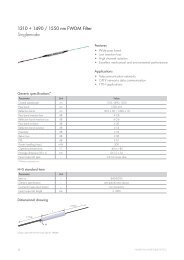
2.3.3 Compliance with sealing requirements<br />
2.3.3.1 Sencity ® <strong>Rail</strong> with possibility of connecting a conduit guide<br />
The Sencity ® <strong>Rail</strong> antenna, which offers the possibility of connecting a conduit guide to its base<br />
plate should be used in this case. This is available from different suppliers (e.g. from<br />
http://www.pma.ch/ 1 ). The IP rating depends of the used conduite guide.<br />
The thread in the base plate is too short <strong>for</strong> the connector of the conduit guide <strong>for</strong> mounting it directly.<br />
But a special ring can be ordered from HUBER+SUHNER, which is mounted in-between<br />
1<br />
A IP68 test has been successfully per<strong>for</strong>med with a product from PMA (PMAFIX Pro connector KNH straight with a M40 thread, metric,<br />
metal: PMA article number: NKNH-M409-13).<br />
9<br />
HUBER+SUHNER – Excellence in Connectivity Solutions
and allows the use of the standard part. The conduit guide protects the cables from the antenna till<br />
the roof of the train from environmental influences (see figure 6).<br />
Figure 6<br />
2.3.3.2 <strong>Antennas</strong> without possibility of mounting the conduit guide<br />
In the case of mounting the antenna on a bracket and to still insure an inside environment, the antenna<br />
should be mounted on top of a sealed box which will create an inside environment <strong>for</strong> the<br />
connector (figure 7).<br />
Figure 7<br />
10<br />
HUBER+SUHNER – Excellence in Connectivity Solutions
2.3.4 Short circuit protection<br />
In case of a brake of the overhead line, the high current has to be earthed to the train roof. The<br />
internal protection of the antenna can only support the high current, if the bracket can absorb the<br />
current of up to 40’000 amperes and discharge it to the roof.<br />
For the Sencity ® <strong>Rail</strong> antennas, which have the possibility of using the ground kit (see 2.2.1.3), this<br />
problem is solved by connecting the antenna via the grounding kit and a copper busbar directly on<br />
earth. In this case, the bracket has not to be designed specially.<br />
3 SPECIAL POINTS<br />
3.1 <strong>Antennas</strong> with active GPS<br />
The LNA of the active GPS needs a DC voltage. Most GPS receivers offer the possibility of inducing<br />
this voltage directly in the RF path to the antenna. Otherwise it can be induced via a DC injector.<br />
The specified voltage must not be exceed. Otherwise it will destroy the LNA. A lower voltage<br />
than specified will not harm the LNA, but the LNA is not going to work properly. Please refer to the<br />
datasheet of the antenna <strong>for</strong> the required DC voltage.<br />
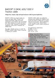
3.2 <strong>Antennas</strong> with passive GPS<br />
For the antennas with passive GPS (ref: 1399.17.0043, 1399.99.0032 and 1399.17.0100), the 5 V<br />
DC feeding of the GPS / Galileo receiver needs to be switched off be<strong>for</strong>e the cable is connected to<br />
the GPS / Galileo port of the antenna. As the GPS / Galileo antenna is DC grounded (compliance<br />
to the UIC 533 standards), the induced short-circuit will damage the GPS / Galileo receiver if it is<br />
not switched off (see figure 8).<br />
Figure 8<br />
11<br />
HUBER+SUHNER – Excellence in Connectivity Solutions
HUBER+SUHNER group is certified according to ISO 9001 and ISO 14001.<br />
WAIVER!<br />
While the in<strong>for</strong>mation contained has been carefully compiled to the best of our present knowledge,<br />
it is not intended as representation or warranty of any kind on our part regarding the<br />
fitness of the products concerned <strong>for</strong> any particular use or purpose and neither shall any statement<br />
contained herein be construed as a recommendation to infringe any industrial property<br />
rights or as a license to use any such rights. The fitness of each product <strong>for</strong> any particular<br />
purpose must be checked be<strong>for</strong>ehand with our specialists as this guideline is intended <strong>for</strong><br />
general in<strong>for</strong>mation purposes only<br />
HUBER+SUHNER AG<br />
RF Division<br />
9100 Herisau, Switzerland<br />
Phone +41 (0)71 353 41 11<br />
Fax +41 (0)71 353 45 90<br />
www.hubersuhner.com<br />
HUBER+SUHNER – Excellence in Connectivity Solutions<br />
Document no.: DOC-0000296064 Uncontrolled Copy<br />
Issue no.: 8 Issued/Checked/Released: 4735/4772/02.2009<br />
Supersedes: 09.2009 Last amended: 4735/10.2009<br />
12<br />
HUBER+SUHNER – Excellence in Connectivity Solutions