SERVICE BULLETIN - Extra Aircraft
SERVICE BULLETIN - Extra Aircraft
SERVICE BULLETIN - Extra Aircraft

You also want an ePaper? Increase the reach of your titles
YUMPU automatically turns print PDFs into web optimized ePapers that Google loves.
EXTRA Flugzeugproduktionsund<br />
Vertriebs-GmbH<br />
Schwarze Heide 21<br />
46569 Hünxe, Germany<br />
Service Bulletin<br />
EA-400<br />
NLG Hydraulic Actuator<br />
<strong>SERVICE</strong> <strong>BULLETIN</strong><br />
No. 400-2-04<br />
Compliance mandatory<br />
Subject:<br />
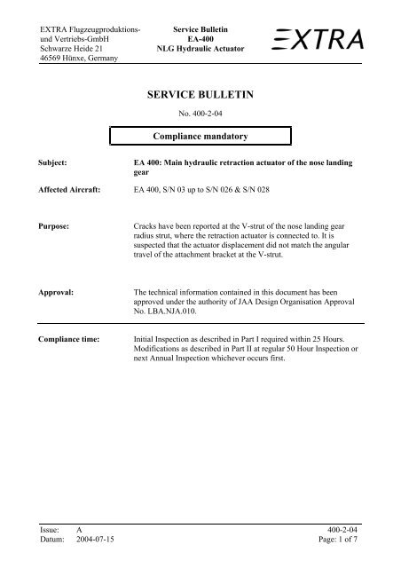
EA 400: Main hydraulic retraction actuator of the nose landing<br />
gear<br />
Affected <strong>Aircraft</strong>: EA 400, S/N 03 up to S/N 026 & S/N 028<br />
Purpose:<br />
Cracks have been reported at the V-strut of the nose landing gear<br />
radius strut, where the retraction actuator is connected to. It is<br />
suspected that the actuator displacement did not match the angular<br />
travel of the attachment bracket at the V-strut.<br />
Approval:<br />
The technical information contained in this document has been<br />
approved under the authority of JAA Design Organisation Approval<br />
No. LBA.NJA.010.<br />
Compliance time:<br />
Initial Inspection as described in Part I required within 25 Hours.<br />
Modifications as described in Part II at regular 50 Hour Inspection or<br />
next Annual Inspection whichever occurs first.<br />
Issue: A<br />
400-2-04<br />
Datum: 2004-07-15 Page: 1 of 7
EXTRA Flugzeugproduktionsund<br />
Vertriebs-GmbH<br />
Schwarze Heide 21<br />
46569 Hünxe, Germany<br />
Service Bulletin<br />
EA-400<br />
NLG Hydraulic Actuator<br />
PART I:<br />
Instructions:<br />
Part I of this Service Bulletin provides initial instructions.<br />
Visual check bracket at V-strut of the nose landing gear radius strut (where the main<br />
hydraulic actuator connects) for cracks, especially the root area of bracket, ref. to fig.<br />
1.<br />
Fig. 1: Overview NLG retraction devices<br />
If cracks are suspected, a further detailed inspection is necessary. Disconnect both<br />
retraction actuators as well as the gas spring from the V-strut (refer to the provisions of<br />
Maintenance Manual Chapter 32-30-24 and 32-30-25) for that purpose. Disassemble<br />
the V-strut, remove paint at suspected area and perform a dye-check.<br />
If no structural cracks are found, replace surface treatement in accordance with chapter<br />
51-70-07 of Maintenance Manual EA-400 and reinstall strut, connect retraction<br />
actuators and gas springs.<br />
Make an airframe logbook entry indicating compliance with the initial visual<br />
inspection requirements of this SB. Indicate in the entry the Part II of this SB to be<br />
accomplished at regular 50 Hour Inspection or next Annual Inspection, whichever<br />
occurs first.<br />
If structural cracks are found, replace or repair V-strut (refer Maintenance Manual<br />
Chapter 51-70-05 & Chapter 51-70-07) and continue with provisions of Part II.3<br />
Report structural damage found to:<br />
EXTRA Flugzeugproduktions- und Vertriebs-GmbH<br />
using the form at the appendix of this Service Bulletin.<br />
Issue: A<br />
400-2-04<br />
Datum: 2004-07-15 Page: 2 of 7
EXTRA Flugzeugproduktionsund<br />
Vertriebs-GmbH<br />
Schwarze Heide 21<br />
46569 Hünxe, Germany<br />
Service Bulletin<br />
EA-400<br />
NLG Hydraulic Actuator<br />
PART II:<br />
Modifications:<br />
Material:<br />
Instructions:<br />
Part II of this Service Bulletin provides instructions for technical modifications to the<br />
main nose landing gear retraction hydraulic actuator.<br />
Spacer bushing installation in the main hydraulic actuator of NLG limiting the stroke<br />
of piston rod in extended gear position in accordance to the instructions.<br />
Spacer bushing P/N: 40553415 (oversize bushing)<br />
O-Ring MS 28775-111,<br />
O-Ring MS 28775-117<br />
Packing MS 28774-111<br />
Quantity: 1 each<br />
A kit is available, please contact:<br />
EXTRA Flugzeugproduktions- und Vertriebs-GmbH<br />
Schwarze Heide 21<br />
46569 Hünxe (Germany)<br />
Fax. N°: (+49)-2858-9137-30<br />
Part II of this Service Bulletin has to be performed at <strong>Extra</strong> facilities or by licensed<br />
personal at maintenance stations.<br />
The installation of the spacer bushing in the nose landing gear hydraulic actuator has to be done in<br />
accordance to the following steps:<br />
1. <strong>Aircraft</strong> is jacked up in the shop, landing gear extended, hydraulic pressure off (refer MM<br />
Chap. 32-30-24 above Step 2)<br />
2. Disconnect both retraction actuators as well as the gas springs from the V-strut (refer to the<br />
provisions of Maintenance Manual Chapter 32-30-24 and 32-30-25) for that purpose.<br />
Remove end switch for extended position. Disassemble radius strut (V-strut and T-strut)<br />
3. Check overcenter adjust of radius strut. If deviate from 1mm (see fig. 2&3) adjust by screw.<br />
Issue: A<br />
400-2-04<br />
Datum: 2004-07-15 Page: 3 of 7
EXTRA Flugzeugproduktionsund<br />
Vertriebs-GmbH<br />
Schwarze Heide 21<br />
46569 Hünxe, Germany<br />
Service Bulletin<br />
EA-400<br />
NLG Hydraulic Actuator<br />
Fig. 2: Radius strut adjustment<br />
Fig. 3: Testing of radius strut adjusting (for example)<br />
4. Reinstall radius strut and both hydraulic actuators. Reinstall end switch; verify the switch is<br />
activated if the radius strut has overcentered (check acoustically or by observing the green<br />
indicator light).<br />
5. Install marking device (metallic block or angle, fixed by means of a clamp), at piston rod of<br />
main hydraulic actuator, similar to fig. 4., fixed without gap between cylinder housing and<br />
marking device.<br />
Fig. 4: Marking device<br />
Issue: A<br />
400-2-04<br />
Datum: 2004-07-15 Page: 4 of 7
EXTRA Flugzeugproduktionsund<br />
Vertriebs-GmbH<br />
Schwarze Heide 21<br />
46569 Hünxe, Germany<br />
Service Bulletin<br />
EA-400<br />
NLG Hydraulic Actuator<br />
6. Disengage connection between main hydraulic actuator and trunion.<br />
7. Caution: Make sure that the landing gear control handle is still in the “down” position.<br />
Activate hydraulic pressure, nose gear main hydraulic actuator piston rod will move to the<br />
max. position.<br />
8. Measure the additional travel of the piston rod (gap X between cylinder housing and<br />
marking). This is the needed length for the spacer bushing.<br />
9. Remove marking device. Deactivate hydraulic pressure by loosing the hydraulic line<br />
connections. Remove main hydraulic actuator. Note: Catch spilling hydraulic fluid with<br />
suitable vessel.<br />
10. Shorten the delivered bushing in accordance to the drawing to the measured length X +/-<br />
0.1 mm.<br />
11. Note the relative position of the rod end vs. piston rod before you disassemble the actuator.<br />
Fig. 5: Main hydraulic actuator<br />
12. Disassemble the counter nut and rod end from piston rod (14&15).<br />
13. Disassemble the Seegerring (8)<br />
14. Pull the guidance (4) with the piston rod (3) out of the hydraulic actuator bore. The piston<br />
should remain within the actuator bore. Note: Catch spilling hydraulic fluid with suitable<br />
vessel.<br />
15. Pull the guidance (4) from piston rod (3).<br />
16. Push the spacer bushing onto the piston rod (3)<br />
Fig. 6: Installed spacer bushing<br />
Issue: A<br />
400-2-04<br />
Datum: 2004-07-15 Page: 5 of 7
EXTRA Flugzeugproduktionsund<br />
Vertriebs-GmbH<br />
Schwarze Heide 21<br />
46569 Hünxe, Germany<br />
Service Bulletin<br />
EA-400<br />
NLG Hydraulic Actuator<br />
17. Replace the O-ring & packing of the guidance (7&18).<br />
18. Reassemble the guidance to the cylinder bore.<br />
19. Secure the guidance with the Seegerring to the cylinder.<br />
20. Screw the rod end into the piston rod until the original measurement is reached. Secure<br />
with counter nut.<br />
21. Reinstall actuator, connect to V-strut bracket.<br />
22. Connect and tighten the hydraulic line connection.<br />
23. Activate hydraulic pressure; the connecting bolt should be easy placed into position on<br />
trunion. Reassemble connection between cylinder and trunion.<br />
24. Install gas springs in reverse sequence of removal.<br />
25. Perform landing gear test, bleed introduced air from hydraulic system by several retraction<br />
cycles. Check oil level at hydraulic power pack.<br />
26. Check overcenter adjustment: when landing gear is extended, there must be no gap<br />
between adjust screw of the radius strut and its related overcentering stop. Check by a sheet<br />
of paper.<br />
27. Certify compliance with this SB in airframe logbook and maintenance manual. Make a log<br />
book entry indicating compliance with the inspection and retrofit requirements of this SB.<br />
Issue: A<br />
400-2-04<br />
Datum: 2004-07-15 Page: 6 of 7
EXTRA Flugzeugproduktionsund<br />
Vertriebs-GmbH<br />
Schwarze Heide 21<br />
46569 Hünxe, Germany<br />
Service Bulletin<br />
EA-400<br />
NLG Hydraulic Actuator<br />
Appendix:<br />
<strong>Aircraft</strong> Type and model: EA-400 Serial Number:<br />
Owner:<br />
Total Time:<br />
Registration:<br />
Total landings (if known):<br />
_______________________________________________________________________________<br />
The aircraft mentioned above has been inspected according the provisions of this Service Bulletin<br />
SB 400-2-04<br />
Damage has been found: □ Yes □ No<br />
If yes, description of damage found (if possible attach supporting sketch):<br />
Comments:<br />
Company:<br />
________________<br />
<strong>Aircraft</strong> inspector: ________________ Date: __________________<br />
Please return a copy of this page by facsimile or airmail to:<br />
EXTRA Flugzeugproduktions- und Vertriebs-GmbH<br />
Engineering Department / Office of Airworthiness / Quality Assurance<br />
Schwarze Heide 21<br />
46569 Hünxe (Germany)<br />
Fax. N°: (+49)-2858-9137-42<br />
Issue: A<br />
400-2-04<br />
Datum: 2004-07-15 Page: 7 of 7